
Abstract
Producing quality features with abrasive waterjet milling requires the generation of shallow kerfs with low surface waviness. Typically, such kerfs are produced by deformation wear mode of material removal realized with certain combination of process parameters chosen based on an elaborate experimental analysis. Instead, these parameters can be selected through a modeling methodology developed based on deformation wear erosion theory. As a first part of this development, it is essential to identify the conditions for the prevalence of deformation wear during the generation of shallow kerfs with abrasive waterjets. To establish this condition, this article presents a theoretical analysis of kerf formation formulated based on deformation wear erosion by solid particles. In this analysis, the interaction of the abrasive particles with the material and the subsequent material removal through deformation wear is considered to define the geometry of the cutting front. The geometry of the cutting front was then used to determine the condition at which local impact angle of abrasives striking the cutting front changes to alter the mode of material removal from deformation wear to cutting wear. This analysis has brought out the boundary condition for deformation wear as the maximum depth of kerf to be equal to the average size of the abrasive particles used in the jet. The generic nature of this condition is established with kerfing experiments over three different ductile materials.
Keywords
Introduction
Abrasive waterjet (AWJ) machining is one of the several well-established energy beam based non-conventional machining process with an exquisite potential to machine hard to process materials. 1 The potential exhibited by this process for profile cutting applications led to several explorative efforts toward utilizing the tool for performing different machining applications such as drilling, piercing, turning and milling.2,3 Among these processes, milling with AWJ is a controlled depth surface generation process, wherein discrete kerfs are combined together to form surfaces of certain geometry. These kerfs are produced by eroding the material with an AWJ traversed over the material along a predetermined path. The path is designed in such a way that a series of kerfs merge together to generate the desired geometry over the material. However, the irregular nature of kerf surface and the non-deterministic nature of kerf shape pose a major challenge to realize quality features with this process. Both the geometry of kerf and its surface quality are dependent on the energy flux parameters such as water pressure, abrasive flow rate, abrasive particle size, jet traverse speed, stand-off distance (SOD), jet orientation and the geometry of orifice and nozzle. 1 Among these parameters, the jet traverse speed has been found to be the crucial energy flux parameter that controls the depth of kerf and, in turn, the shape of kerf and the waviness on kerf surface.4–10 The kerf depth has been observed to change from a few millimeters to a few hundred micrometers, with the increase in the jet traverse speed from 1000 to 10,000 mm/min.4,6 Similarly, the waviness on kerf surface has also reduced to a few micrometers on shallow kerfs.4–7 Furthermore, the cross-sectional shape of kerf has also been observed to change from an inverted Gaussian profile to a uniform profile, when the depth of kerf has changed from few hundred microns to few tens of microns.4,6 Moreover, as the kerf depth reduces from few millimeters to few micrometers, the mode of material removal has also been observed to change from cyclic cutting mode to cutting wear (CW) mode and then to deformation wear.4,5,11,12 The reduction in waviness over shallow kerf surface produced by deformation wear mode of material removal has been attributed to the absence of deflection of the jet, which in turn has avoided the secondary erosion of material over kerf surface.11–13
All the above observations clearly highlight the need to select traverse speeds that can generate shallow kerfs by deformation mode of material removal, so as to produce these kerfs with low surface waviness and simpler kerf shapes. However, the exact range of traverse speeds over which the deformation wear mode prevailed is not clearly known. This is due to the influence of other parameters such as water pressure, SOD and orientation of the jet employed during kerf formation, on the range of jet traverse speeds for deformation wear mode of material removal. It has been observed that the deformation wear can occur over a wide range of traverse speeds from 200 to 5000 mm/min when the choice of other parameters is made from a wide range: water pressure (100–400 MPa), SOD (5–70 mm) and jet orientation (90°–30°).6–16 From these observations, it is clear that several combinations of parameters can be chosen to generate a shallow kerf by deformation wear mode of material removal. In view of this complexity, it is normal practice to conduct a set of kerfing experiments for identifying the parameters that produce a shallow kerf with minimum waviness on its surface. Subsequently, these parameters are used to produce a series of kerfs and are overlapped, with a certain ratio of overlap, to generate uniform surface by AWJ milling. Although this experimental methodology has been adopted for producing precise iso-grid structures,17,18 pockets,19,20 slots 21 and contoured surfaces, 22 the process of selecting the parameters for kerf generation and the method of tool path design are based on empirical studies and quite elaborate investigation of surface topography. Such tediousness can be avoided by developing models that can easily predict the process parameter combinations needed to generate a shallow kerf with minimum surface waviness by deformation wear mode of material removal.
A brief review of the available modeling techniques related to AWJ milling shows that almost all the efforts have been focused toward modeling of kerf shape and their subsequent use for tool path planning. Although certain specific efforts have also been made to predict certain features of kerf geometry such as kerf width, they are few in number. 23 The most popular method of modeling the kerf geometry considers the actual shape of kerf produced on the materials employing a set of parameters and then uses the width and depth of kerf to formulate a function that closely represents the contour of kerf. Mostly, Gaussian and cosine functions have been seen to represent the geometry of kerf.14,24,25 By considering these distribution functions for kerf shape and using the principle of superposition, the overlapped tool paths for producing planar surface geometry have been developed. A serious limitation of this method is the validity of the distribution function only for a set of energy flux conditions that have been used to produce the kerf geometry. Moreover, this approach of modeling does not consider the magnitude of waviness on kerf surface nor does it enable one to determine the energy condition that can minimize the waviness on kerf surface. Another method that involves the use of experimental shape of kerf relates the experimentally obtained kerf shape to the erosion rate function derived analytically.26–28 The calibrated erosion rate function has then been used to model the kerf shape based on the assumption of linearity of erosion rate over a range of process parameters. While this method is generic in nature to predict kerf shape under selected conditions, the assumption of linearity of erosion rate would require that both the mode of erosion and the local impact angle of abrasive remain constant over the domain of modeling, that is, over a range of process parameters. Also, the assumption of superposition in both these methods would require that the actual kerf has very low magnitude of waviness, so that the predicted three-dimensional (3D) kerf shape closely matches with the actual 3D shape of kerf. Both these assumptions, in turn, would require a prior knowledge of the range of parameters such as traverse speed, water pressure, mass flow rate and SOD, which will ensure that the kerf produced has minimum surface waviness and also ensure that the local impact angle and mode of erosion will remain constant. Due to the reverse engineering nature of these modeling techniques, this knowledge is often acquired through an experimental analysis. This clearly shows that even kerf shape modeling techniques continue to rely on experimental methodology to identify operating domains. In contrast to these techniques, finite element–based erosion models have been used to predict the shape of kerf under certain conditions, generally employed for AWJ milling.29–32 This method has shown a huge potential to accurately predict kerf shapes as well as design tool paths, but the present formulations have also been made under experimentally predetermined operating domains. The use of such models to predict optimum energy flux parameters that are suitable to generate quality kerfs is yet to be explored.
From the above review of literature, it can be summarized that to generate a kerf surface with minimum waviness, it is essential to determine suitable combination of energy flux parameters such as jet traverse speed, water pressure, SOD and jet orientation. It is also clear that under such conditions, the generated kerf will be shallow and the mode of material removal will be predominantly deformation wear. However, identifying such conditions is seen to require an elaborate experimental methodology. While kerf shape modeling techniques have simplified certain aspects of tool path design such as the determination of overlap ratio between kerfs, their formulation is still dependent on experimentally derived kerf characteristics. Furthermore, these models are also not capable of identifying the conditions for generating quality kerfs for milling applications.
Hence, it is important to develop a comprehensive method that can help identify the exact set of conditions suitable for producing kerf surface with minimum irregularities. These identified conditions can then be used to predict the kerf shapes required for tool path planning. Development of such a method can be addressed by fundamentally analyzing the nature of material removal with a high-speed jet impacting the surface with certain energy flux. As the mode of material removal suitable for generating shallow kerf with minimum waviness is seen to be deformation wear, relevant erosion theories can be used to develop the modeling methodology. However, to model the process based on deformation wear theory, the appropriate conditions for the prevalence of deformation wear mode during AWJ blind kerfing process need to be established. The prevalence of deformation wear in AWJ blind kerfing can be determined by predicting the condition up to which the impact of the abrasive particle remains at high angles (90°–60°) of impact. This argument is plausible since the geometry created by the removal of material is expected to change the local impact angle of abrasives striking the cutting front. Thus, this particular idea was used to formulate the boundary conditions for deformation wear mode in terms of the geometry of the cutting front.
Methodology
The methodology adopted to generate the cutting front geometry produced by a traversing AWJ, so as to derive the local impact angle of the abrasive particle on this cutting front and to determine the boundary conditions for deformation mode of material removal is given as follows:
Establishment of the relationship between jet energy flux parameters and material removal mechanism to determine the basic geometry formed on the material due to the interaction between abrasive particle and material.
Derivation of the expression for representing the geometry of the cutting front generated due to the coalescence of several geometries formed due to erosive action of several abrasive particle streams in the jet traversed along a particular direction.
Derivation of the expression for determining the local impact angle of the abrasive particle striking the cutting front, so as to determine the boundary condition for realizing deformation wear in terms of the geometry of the cutting front.
Validation of the boundary condition for deformation wear with experimentation on different ductile materials.
Theoretical analysis
The boundary condition for deformation wear mode can be derived by considering the nature of material removal caused by an AWJ traversing over the material.
Various assumptions made to derive the expression for the boundary condition are as follows:
The distribution of the abrasive particles in the jet follows a Gaussian distribution.
SOD is assumed to be low in the range of 3–5 mm.
All the particles are assumed to have uniform velocity at low SODs, since the jet divergence is low and the velocity of abrasives in the jet is found to be uniform.33,34 This assumption is not valid at higher SODs since the jet diverges into a wider jet and the velocity of the abrasive particles follows Gaussian distribution.
The diameter of the jet is assumed to be equal to the diameter of focusing nozzle, at lower SODs, that is, below 5 mm. This assumption is not valid beyond these SODs since the divergence of the jet increases the diameter of the jet.
The orientation of the jet is at 90° to the material surface. Jet orientation at 90° alone is considered since it has already been shown elsewhere that planar and non-planar surfaces can be produced with this setup. 22
All the particles are assumed to be spherical in shape having a diameter ‘dp’. While the particles, commonly used in AWJ machining, are angular in nature, they are represented as spherical particles due to the following reasons:
(a) More than 80% of the particles have a multi-faceted polygon shape rather than a sharp conical or pyramid geometry. Therefore, the area of impact and the field of deformation are much closer to a spherical abrasive particle. Moreover, sharper particles also tend to be much smaller than the average diameter of particles and do not contribute significantly to the material removal.1,35–37
7. The model is formulated based on the deformation wear mode of material removal, wherein the particle impacts at normal angles. Under these conditions, the angular edges of the abrasive particle are only efficient if the center of gravity of particle is directed through the sharp edge. Since this condition is not always true, the particles tend to rotate on impact, thereby reducing the energy available for causing indentation. 1 Furthermore, the variation in size and angularity of particles change the field of deformation of impact. To account for the loss of energy through particle rotation and the variation in the field of deformation, the effect of multi-faceted polyhedron particle impact is normalized by considering repeated impacts of similar nature with several equi-sized spherical abrasive particles, which are ejected out of the nozzle with their center of gravity oriented at 90° to the initial flat surface.
8. Inter-particle collision and collision of rebounding particle with incident particle are assumed to be negligible. This assumption will also ensure that the frequency of inter-particle collision is less and is valid when abrasive loading ratios, that is, mass flow rate of abrasive to mass flow rate of water, are less than 50%.
Relationship between energy flux and geometry formed due to material removal
Figure 1(a) shows several particle streams in the jet that are traveling toward the material surface at velocity ‘Va’, while the nozzle delivering the particles traverses in a direction perpendicular to the direction of particles at velocity ‘u’. Due to Gaussian distribution of the abrasive particles, the particles are concentrated toward the center of the jet. As a result, the central region of the jet has higher energy content and will cause maximum surface gradients along the cutting front. Therefore, the interaction of several parallel particle streams in the center of jet (Figure 1(b)) alone is considered to define the geometry of the cutting front. If the abrasive streams are closely spaced, then the number of parallel streams ‘M’ that are available at the central region of jet along the traverse direction can be estimated from
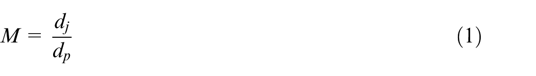
where dj is the diameter of the jet and dp is the diameter of the abrasive particle.
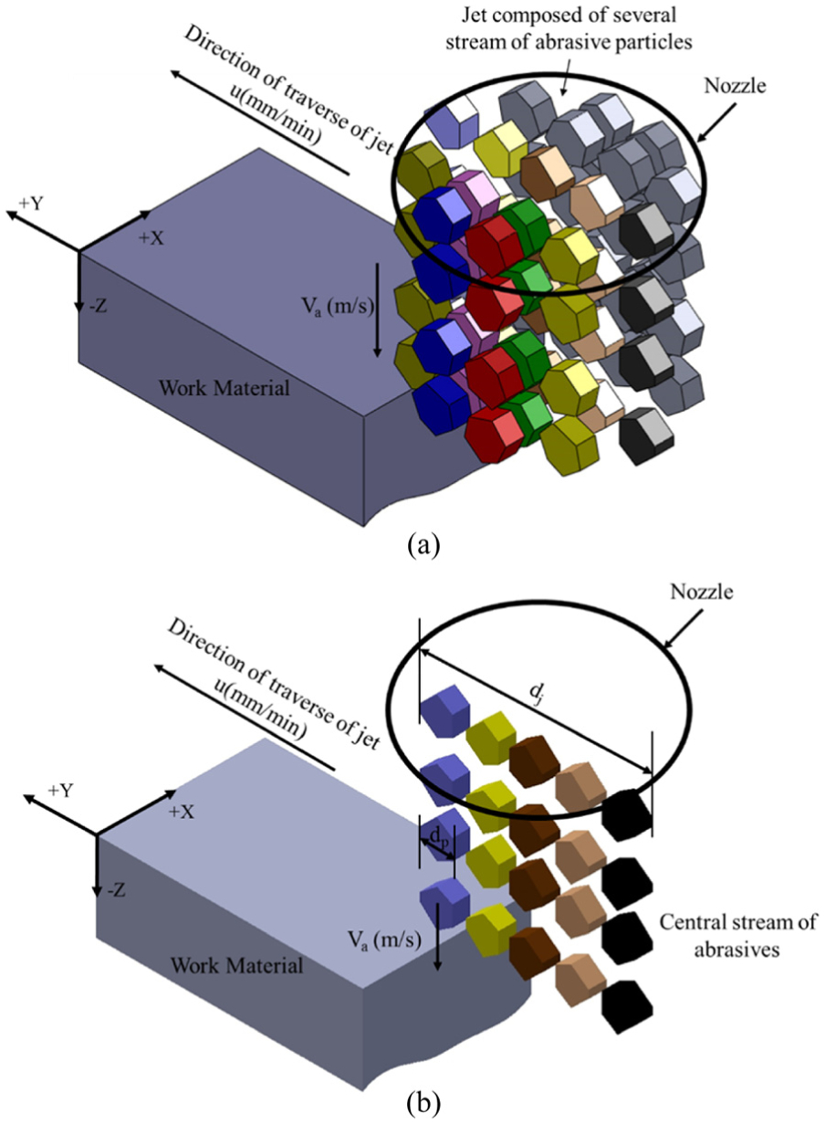
Schematic illustration of (a) several particle streams in abrasive waterjet of diameter ‘dj’ traversing over the material at speed ‘u’ and (b) several parallel particle streams at the center of jet traveling over the material at speed ‘u’.
The number of particles ‘Ni(t)’ in each stream at any instantaneous time ‘t’ varies and can be determined from
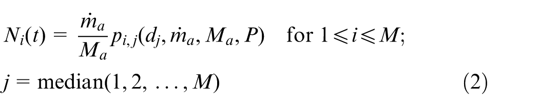
where pi,j (dj,
At any instantaneous time ‘t’, the first particle in the first stream impacts the flat surface and produces a crater as shown in Figure 2(a).
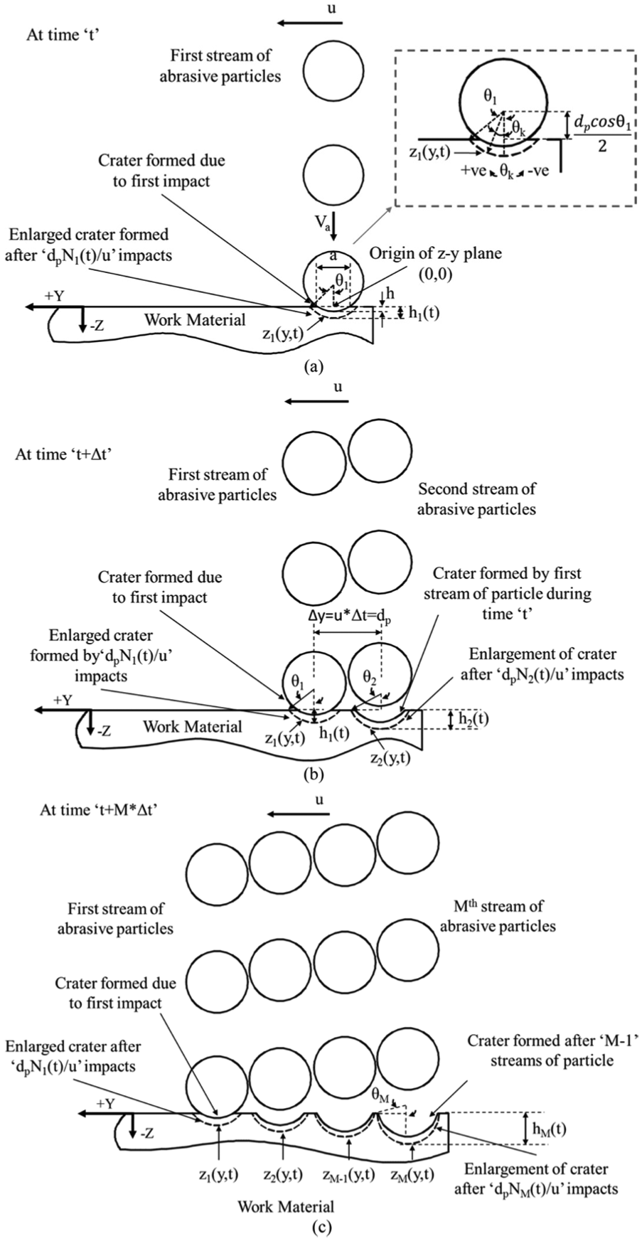
Schematic illustration of crater formation by several parallel streams of abrasive particle: (a) single stream, (b) two streams and (c) M streams.
The volume of material, ‘Vcsp’, displaced by this impact can be calculated by equating the kinetic energy of spherical abrasive particle to the energy required to produce an indentation on the material, that is
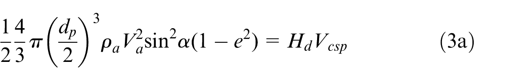
Rearranging equation (3a), we get the volume of the material displaced as
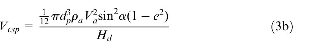
where ρa is the density of the abrasive particle, Va is the velocity of the abrasive particle, Hd is the dynamic hardness of the material due to single spherical particle impact,
From the geometry of the crater shown in Figure 2(a), the volume of crater ‘Vcsp’ can be estimated from
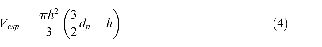
where ‘h’ is the depth of indentation.
From equations (3b) and (4), the expression for ‘h’ can be obtained as
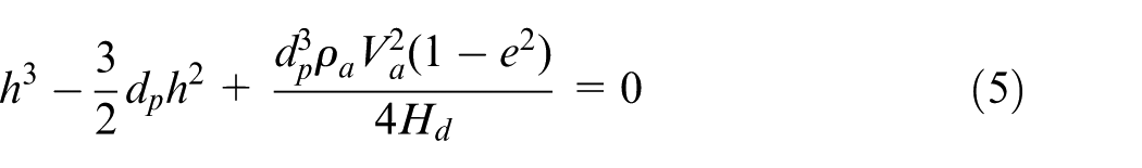
By solving equation (5), ‘h’ can be determined.
With multiple similar impacts of the particles in the first stream, the depth and width of the crater can grow. The depth of crater ‘h1(t)’ after
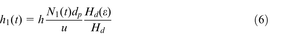
where Hd(ε) is a function representing the dynamic hardness of the material at a particular strain ‘ε.’
By knowing ‘h1(t)’ and the diameter of abrasive particle ‘dp’, the two-dimensional geometry of this crater along ‘y–z’ plane, with reference to the coordinate system shown in Figure 2(a), can be described as
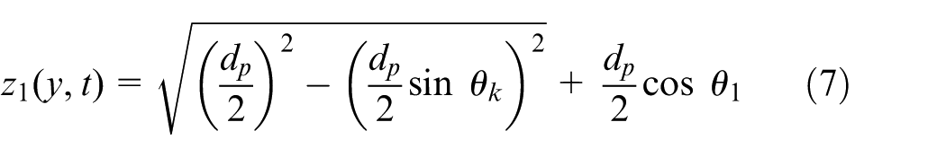
where θk is the included angle at the center of crater, at any given location along the crater profile, shown in Figure 2(a) and is positive in the clockwise direction and negative in the counter clockwise direction when measured from the center. Its value varies in the range of
In equation (7), the computation of the square root term yields both positive and negative values of equal magnitude. The negative value is used to compute the variation in ‘z’ along ‘y’.
Expression for representing the geometry of cutting front
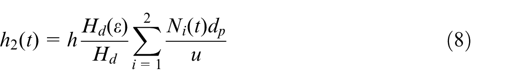
The geometry of the cutting front produced by the interaction of M streams contained in the central region of the jet is determined by combining the geometry of adjacent craters formed by each individual stream. At a small incremental time interval ‘t + Δt’, the position of impact of all the streams would have shifted forward by a distance ‘Δy = u*Δt’. This distance can be conservatively taken to be equal to the diameter of the abrasive particle such that it avoids collisions with particle impacting in the previous time frame, ‘t’. As shown in Figure 2(b), the first stream of the abrasive particles would now produce a crater of h1(t) at this location ‘y + Δy = dp’, while the second stream of the abrasive particles will now interact with the previously formed crater at ‘y = 0’ over time ‘t’. As a result of this, the depth of crater at y = 0 increases to ‘h2(t)’ and the diameter of crater enlarges to ‘a2(t)’. The depth ‘h2(t)’ of the enlarged crater can be given as
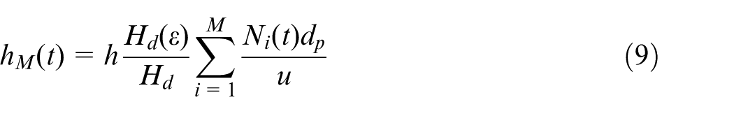
In a similar manner, as shown in Figure 2(c), at certain time interval ‘t + M*Δt’, all the particles in the jet start to interact with the material, with each trailing stream enlarging the crater formed by their previous stream in the previous time frame, while the first stream continues to interact with the un-machined region. Due to this phenomenon, the depth of crater at ‘y = 0’ formed at the end of impacts of ‘M’ stream of the abrasive particles can be obtained as
Since all these craters together represent the geometry of the cutting front, the equation representing the geometry of the cutting front can be established by combining the geometry of individual craters with a common reference frame of coordinates.
The geometry of the crater (Figure 2(b)) at ‘y = 0’ produced as a result of interaction of two streams of abrasive particles can be represented with reference to the same coordinate system shown in Figure 2(a) as
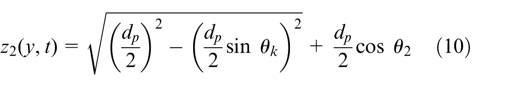
where θk varies from
In a similar manner, the geometry of the crater formed by ‘Mth’ stream at ‘y = 0’ (Figure 2(c)) can be represented with reference to the same coordinate system as
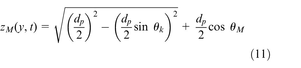
where θk varies from
Now, the geometry of cutting front ‘Z(y, t)’ formed by all these craters can be represented with respect to a common reference point as
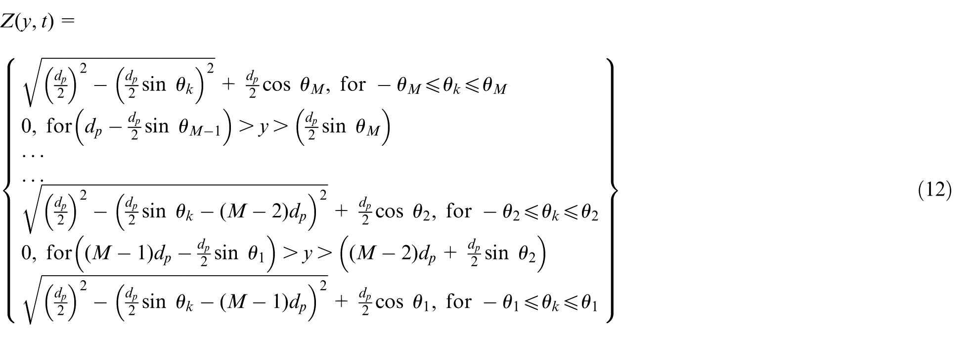
where
Boundary condition for deformation wear mode of material removal
The local impact angle of the abrasive on the cutting front can be obtained by differentiating equation (12) with respect to ‘θ’. It is well known that the kinematics of the abrasive particle impacting the local curvature of the craters is restricted by the geometry of the crater. Therefore, the kinematics of the particle and as a result the mode of material removal does not undergo a major change when the craters are shallow and isolated. The change in kinematics of the particle starts to become significant when adjacent craters start to merge together into one entity.
The craters will begin to merge with the removal of the material between the craters, as shown in Figure 3(a). The material removed under deformation wear can be explained with the theory of localization of deformation.38–40 As the crater grows, the material normal to the crater surface undergoes strain. At certain critical strain accumulation, the deformed material forms as extruded lips around the edges of the crater, as shown in Figure 3(b). When the two adjacent craters grow as shown in Figure 3(c), the material between the craters undergoes severe strain due to the strain field of these two craters and gets isolated. This severely strained material is easily removed by the force of impact of adjacent abrasives. In AWJ kerfing, the craters formed by two adjacent streams of the abrasive particles will begin to merge, when the depth of these craters is more than ‘dp/2’. Due to the Gaussian distribution of the particles in the jet, certain adjacent streams near the center of the jet will have the same number of the abrasive particles.
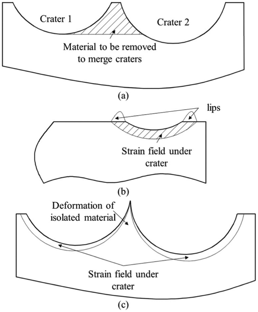
Schematic representation of (a) isolated material between two craters, (b) strain field underneath crater and the formation of deformed material as lips on the edge of crater and (c) strain field under two craters deforming the isolated material.
As shown in Figure 4(a), under the equal number of particle impacts, the size of the adjacent craters will grow in the ratio of 1:2. Therefore, if one of the craters is at a depth ‘dp/2’, the other crater will have a depth of ‘dp’. This represents the condition at which any two adjacent craters will merge with one other. The geometry of these combined craters can be given as
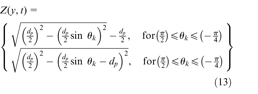
where
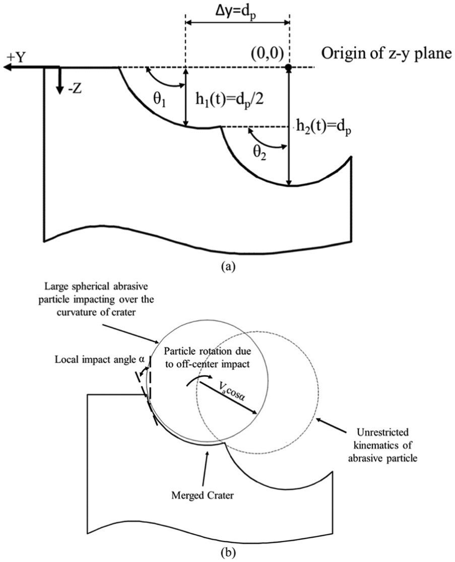
Schematic representation of (a) the geometry of two adjacent craters growing at a ratio of 1:2 and (b) kinematics of abrasive particle impacting the merged craters.
Equation (13) represents the geometrical condition on the cutting front at which the impact angle of the abrasives starts to undergo a significant change. As seen in Figure 4(b), the kinematics of the abrasive particles impacting the curvature of the merged crater is no longer constrained. Therefore, the kinematics of the abrasive particle starts to undergo a change, which in turn will alter the mode of material removal from deformation wear to CW.
Since equation (13) is formulated by considering the condition for the merger of any two adjacent craters, it is sensible to ensure that these merger occur toward the end of kerfing process, that is, at the end of interaction by ‘M’ streams of the abrasive particle. This, in turn, suggests that the maximum depth of crater ‘hM(t)’ formed by ‘M’ streams of the abrasive particles should be less than or equal to ‘dp’, so that the coalescence of the craters is prevented to ensure deformation mode of material removal throughout the kerfing process. Hence, the boundary condition for deformation wear can be given as

Since the above set of equations are formulated by considering the energy flux conditions, these equations can be utilized to determine the energy flux parameters favoring only the deformation mode of material removal.
Experimental
The theoretical analysis covered in the previous section clearly brought out a boundary condition for realizing deformation wear mode of material removal. This condition relates the depth of kerf to the average size of the particle impacting the surface. When the depth of kerf is far below or equal to the size of the abrasives, the mode of material removal will definitely be the deformation mode of material removal. To demonstrate the validity of the proposed theory, kerfing experiments were conducted on three different materials, titanium alloy (Ti6Al4V), stainless steel (316L) and aluminum alloy (6063-T6), having different mechanical properties. These experiments were conducted by considering two different pressures of water, two different abrasive mass flow rates, five different traverse speeds and three different mesh sizes of abrasive particles, so as to produce kerfs with different depths. The particle size distribution in each mesh size and the average diameter of abrasive particles were obtained from the works of Chetty and colleagues,35,36 since the same type of garnet was used in these experiments.
The experimental investigations were conducted with an injection-type AWJ cutting machine capable of delivering water at a maximum pressure of 350 MPa with a rated discharge of 2.2 L/min through an orifice of 0.3 mm diameter. Abrasives are fed into the cutting head using an abrasive feeding/metering system that can control the flow rate of abrasives in the range of 0.06–1 kg/min. The AWJ was formed with cutting head having an orifice of 0.3 mm diameter and was collimated using a focusing nozzle with a bore of 1.2 mm diameter. A two-axis gantry-type computer numerical control (CNC) unit was used to traverse the cutting head at speeds ranging from 1 to 5000 mm/min. Kerfing experiments were conducted by traversing the jet once over the material, at different traverse speeds and jet energy conditions. Different parameter combinations chosen for kerfing experiments on the three different materials are shown in Table 1.
Process parameters employed for kerfing studies on metallic materials.
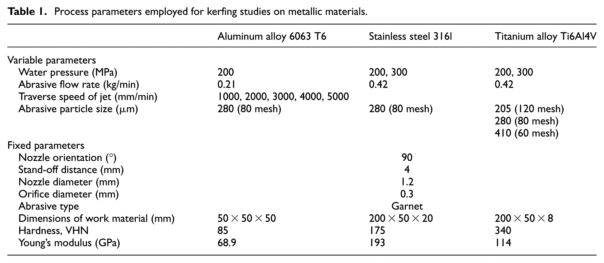
To examine the mode of material removal, the morphology on kerf bottom surface was observed under scanning electron microscope (SEM) and stereo microscope. Laser-based confocal microscope was used to obtain the depth of kerf from the vertical and horizontal scans of kerf surface. A stylus-type profilometer was used to measure the waviness on bottom surface of kerf, and then the magnitude of uniformity on kerf bottom surface was obtained. These measurements were made over a sampling length of 17.5 mm along the kerf track in jet traverse direction. For measuring the waviness over kerfs, more than 0.5 mm deep, the confocal microscope was used since the stylus of the profilometer could not access the bottom surface of deep kerfs.
Results and discussion
To verify the proposed boundary condition, the relationship between material removal mechanism, kerf depth and abrasive particle size needs to be analyzed. The morphology on kerf surfaces produced under all experimental conditions was captured and analyzed to identify the mode of material removal. However, for brevity, one particular set of experiments is presented through optical and SEM micrographs to explain the transition in material removal mechanisms with kerf depth (Figure 5), while other similar results are represented in info-graphical form by categorizing kerf depth based on the mode of material removal (Figure 6).
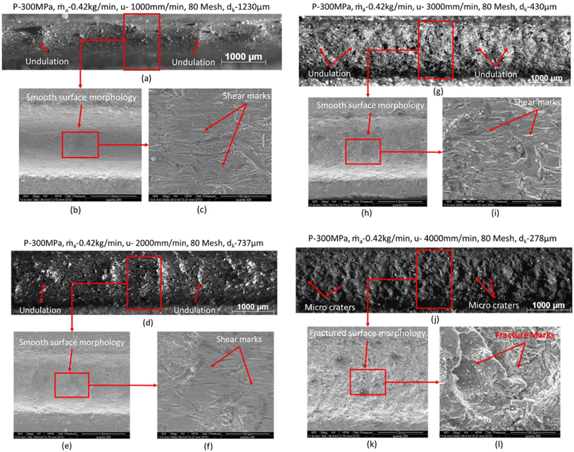
Micrographs of kerf surface produced over titanium alloy: (a) optical micrograph (P: 300 MPa,
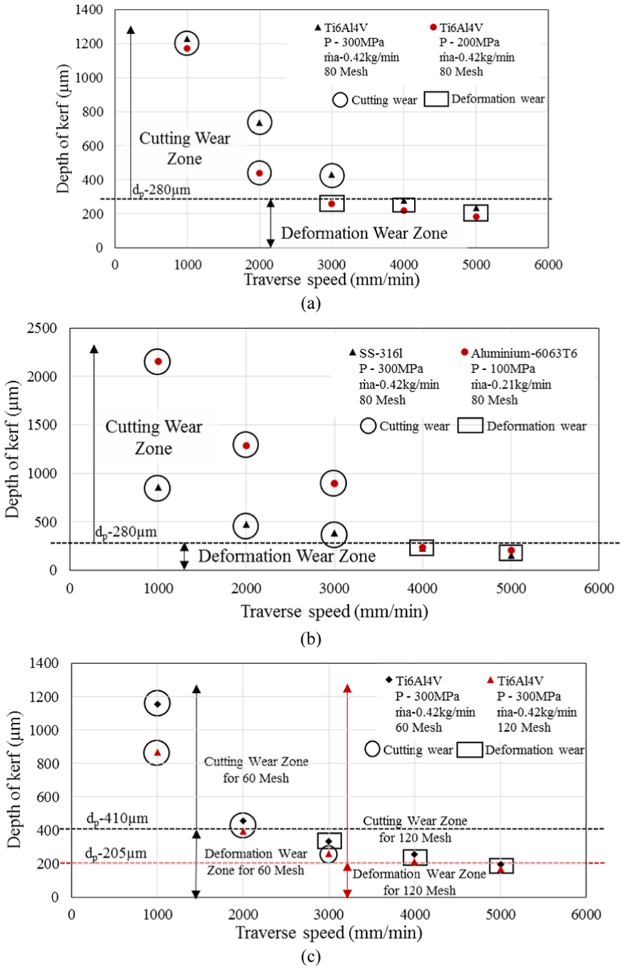
Categorization of experimentally observed kerf depth based on material removal mechanism: (a) titanium alloy: 80 mesh, (b) aluminum and stainless steel alloy: 80 mesh and (c) titanium alloy: 60 mesh and 120 mesh.
Figure 5 shows the morphology over the bottom surface of kerfs produced on titanium alloy with a jet traversed in the speed range of 1000–4000 mm/min and employing a water pressure of 300 MPa, mass flow rate of 0.42 kg/min and abrasive particles of 80 mesh size. The average depth of these kerfs was observed to vary from 1230 to 278 µm (Figure 6(a), P: 300 MPa). From the optical and SEM micrographs, shown in Figure 5(a), (b), (d), (e), (g) and (h), it can be noticed that the surface morphology is smooth at different locations along the kerf track, but the overall surface is undulated. But the depth of these undulations is seen to reduce as the traverse speed increases from 1000 to 3000 mm/min. Higher magnification micrographs of these surfaces shown in Figure 5(c), (f) and (i) show that the surfaces have several shear marks. This type of feature on the surface is generally produced by micro CW with the abrasive particles impacting the surface at oblique angles. These observations clearly show that the impact angle of the particles has changed from an initial normal angle of impact to oblique angle of impact during the formation of kerf. As discussed earlier, this change in impact angle of the abrasives also induces jet deflection and secondary erosion, which can produce several undulations on the surface. But the reduction in the depth of these undulations at higher traverse speeds indicates the reduction in energy flux available for secondary erosion.
In contrast to these observations, the surface morphology on kerf shown in Figure 5(j) and (k) shows up several micro craters distinctly. The depth of micro craters is more or less uniform. At higher magnification, the micrograph (Figure 5(l)) of this kerf surface clearly shows micro cratered and fractured surface. This particular feature on the surface is usually produced through deformation wear erosion by the particles impacting the surface at angles closer to 90°. These observations clearly indicate that the impact angle has remained more or less close to 90° during the formation of kerf, which in turn has avoided jet deflection and secondary erosion of kerf surface. Studying these morphological observation together with the kerf depth (Figure 6(a), P: 300 MPa), it is clear that beyond kerf depth of 300 µm, the mode of material removal changes from deformation to CW. As explained earlier in the theoretical analysis, the reason for this change in material removal mechanism with kerf depth can be attributed to the change in local impact conditions during kerf formation beyond certain kerf depth. At shallow kerf depths, the gradients on the surface created due to material removal are low and does not change the impact angle of abrasives from the initial 90°. However, as more material is removed, the gradients formed on the surface change sufficiently to alter the impact angle, thereby changing the material removal mechanism from deformation to CW.
To precisely quantify the kerf depth at which transition in the mode of material removal occurs and to establish its relation with abrasive particle size, the material removal mechanisms and kerf depth observed under different experimental conditions and on different materials were recorded. The results were plotted as a function of traverse speed, and the domain of CW and deformation wear were marked.
Figure 6(a) shows the categorization of kerf depth based on material removal mechanism on a plot of traverse speed versus kerf depth, observed on kerfs produced on titanium alloy with two different water pressures of 200 and 300 MPa and 80 mesh particle size. From Figure 6(a), it can be seen that across both water pressures, the deformation wear mode is prevalent when the kerf depth is less than 300 µm, whereas CW is prevalent when the depth of kerf is above 400 µm. This indicates a possible transition in the mode of material removal from deformation to CW when the kerf depth exceeds 300 µm. It can also be noted that at water pressure of 300 MPa, the transition occurs between a traverse speed of 3000–4000 mm/min, while at 200 MPa it occurs between 2000 and 3000 mm/min. This clearly highlights that transition in the mode of material removal is not governed by traverse speed or water pressure independently, but in a combined manner, that is, at a particular energy flux condition.
Figure 6(b) shows the results of a similar analysis conducted on kerfs produced on stainless steel alloy at water pressure of 300 MPa and aluminum alloy at water pressure of 100 MPa with 80 mesh abrasive particles. As observed in the previous case, the kerfs produced to a depth below 300 µm were produced by deformation wear, while those above 400 µm were produced by CW, once again indicating a transition from deformation to CW above kerf depths of 300 µm. It is important to note that while the transition occurs at a traverse speed range of 3000–4000 mm/min for both the materials, the water pressure conditions are drastically different. This reiterates the need to select suitable energy flux conditions that can produce kerf under deformation wear.
Now, comparing the kerf depth values to the average diameter of 80 mesh abrasive particle, that is, 280 µm, it can be inferred that the transition in material removal occurs when the depth of kerf exceeds the average particle size as proposed earlier.
Influence of abrasive grit size on the transition behavior
As the proposed boundary condition for deformation wear relates kerf depth to the abrasive particle size, it is necessary to check its validity for different abrasive grit sizes. For this purpose, the kerfs produced on titanium alloy with the abrasive particles having an average diameter of 205 and 410 µm were analyzed, and the results are represented in Figure 6(c). From Figure 6(c), it can be noted that for kerfs produced with 60 mesh particles, the transition in the mode of material removal from deformation to CW occurred when the depth of kerf was above 400 µm. In the case of 120 mesh particles, transition in the mode of material removal occurred when the depth of kerf is above 200 µm.
Comparing these kerf depths with the average diameter of 60 mesh and 120 mesh size abrasives, that is, 410 and 205 µm, respectively, it is clear that the transition in the mode of material removal occurred at a depth of kerf above the average size of the abrasive particles.
All these results ascertain the fact that the transition in the mode of material removal happens whenever the depth of kerf exceeds the average size of the particle contained in the jet. Hence, this particular condition can be used to determine the energy flux parameters needed to produce a kerf under deformation wear.
Importance and use of the proposed boundary condition model
The importance of the proposed boundary condition for deformation wear can be easily understood by the effect of mode of material removal on kerf surface waviness. Figure 7 shows the waviness of kerf bottom surface as a function of traverse speed. From Figure 7(a) and (b), it can be observed that the waviness on kerf bottom surface produced on titanium alloy, stainless steel alloy and aluminum alloy, under deformation wear, is below 50 µm, while waviness of kerfs produced under CW is at least two times higher. The higher waviness under CW is attributed to undulations formed by secondary erosion of the surface by deflected jet. In contrast, secondary erosion phenomenon is absent under deformation wear mode and enables the generation of the surface with low magnitude of waviness. The particle size also plays a major role in the control of waviness. Figure 7(c) shows the waviness on kerf bottom surface observed on kerfs produced on titanium alloy with two different abrasive particle sizes. The waviness on kerf surface produced by smaller particles, that is, 120 mesh, under deformation wear is considerably lower than those produced by other particle sizes, at around 25 µm. Even under certain CW conditions, the waviness is well below 50 µm. This can be attributed to the reduced energy flux available with smaller sized abrasive particle and its lower potential for secondary erosion. On the other hand, the waviness produced by large abrasive particles, that is, 60 mesh, under deformation wear is higher than most, at around 75 µm. The larger crater sizes produced by these particles probably contribute to higher waviness. All these results demonstrate the need to maintain deformation wear mode and also to choose proper particle sizes for producing low magnitude of waviness on the kerf surface.
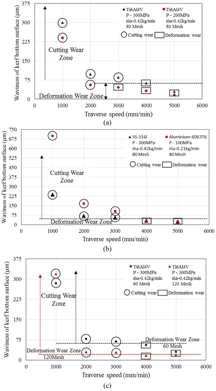
Categorization of experimentally observed kerf bottom surface waviness with respect to mode of material removal: (a) titanium alloy: 80 mesh, (b) aluminum and stainless steel alloy: 80 mesh and (c) titanium alloy: 60 mesh and 120 mesh.
The major use of this proposed boundary condition model comes from the fact that different materials require different combinations of operating parameters for producing kerfs under deformation wear mode of the material. As observed earlier, the process parameter combination at which transition in material removal occurs is different for different materials such as titanium alloy, stainless steel alloy and aluminum alloy. Even for a single material such as titanium alloy, more than one possible combination can be used to produce kerf with deformation wear mode of material removal. Therefore, it is necessary to identify whether a particular combination of parameters can produce a kerf under deformation wear. The proposed boundary condition model can be used for this purpose.
Table 2 presents the results of a computer program simulation of the proposed model. The program predicts whether all the central streams of the abrasive particles, ‘M’, are fully utilized before the kerf depth exceeds the average diameter of the abrasive particle. If nearly all the ‘M’ streams are utilized, it generates an approximate value of kerf depth, ‘hM’. From Table 2, it can be noted that in general at traverse speed range of 1000–2000 mm/min, the number of central streams utilized is less than ‘M/2’. This shows that under these energy flux conditions, the kerf depth exceeds the average diameter of the abrasive particle and is not suitable for producing kerf under deformation wear. This is also confirmed by the experimentally observed CW condition. In contrast, for most traverse speeds in the range of 3000–5000 mm/min, almost all the ‘M’ streams are utilized before the kerf depth exceeds the average diameter of the abrasive particle. A comparison of predicted kerf depth, ‘hM’, and experimentally observed kerf depth, ‘dk’, observed under these energy flux conditions shows that the predicted kerf depths are higher than the experimental observation and are also above the average diameter of the abrasive particle utilized in the jet. This is expected since the model is based on considering similar and repeated impact of the spherical particles, which overestimates the number of effective particle impacts on the surface. But it must be clarified that the present model is developed to predict the transition in material removal and not to accurately predict the kerf depth. Nonetheless, it can be used to quickly identify the suitability of the process parameter combination for producing a kerf depth under deformation wear mode and to obtain an approximate estimate of the expected kerf depth.
Comparison of predicted and experimental results.
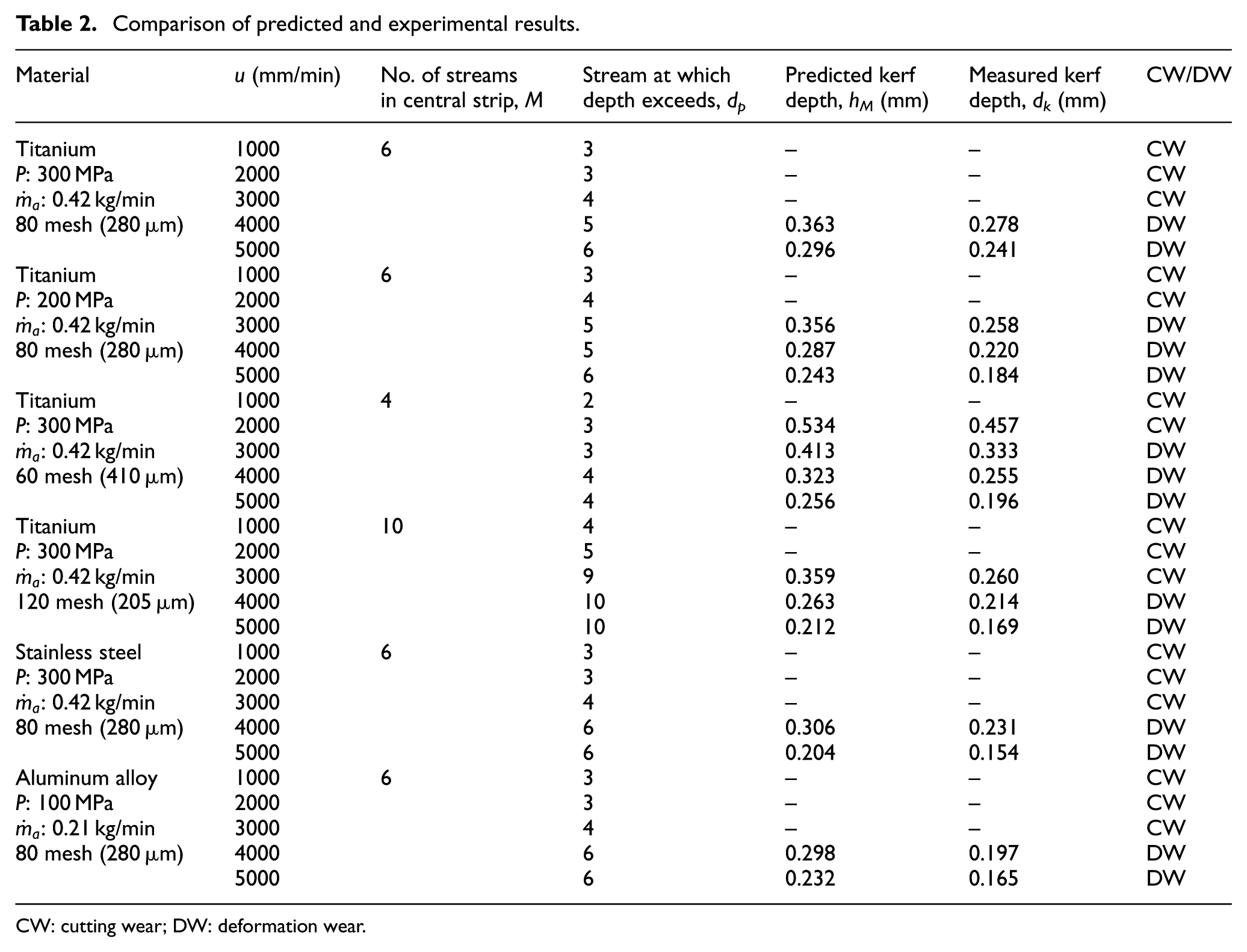
CW: cutting wear; DW: deformation wear.
Conclusion
In this article, an attempt is made to bring out a theoretical analysis to establish the boundary condition for deformation wear mode of material removal in AWJ milling applications. It has considered the interaction between the abrasive particles in the jet and the material to form a cutting front based on deformation wear erosion. The geometry of the cutting front was then used to analyze the change in the impact angle of the abrasives striking this cutting front and their kinematic behavior. This resulted in the determination of the boundary condition for deformation wear erosion as the maximum depth of kerf to be lesser than or equal to the average size of abrasive particle used in the jet. A detailed experimental analysis showed that the boundary condition formulated was indeed valid for different particle sizes and on different materials. Therefore, the condition derived in terms of the kerf depth provides a unique boundary condition with which it is now possible to determine the combination of jet energy parameters and traverse speed suitable for producing kerfs under deformation wear. Future efforts are on toward the utilization of this condition to develop deformation wear erosion–based models for prediction of kerf characteristics.
Footnotes
Appendix 1
Declaration of conflicting interests
The author(s) declared no potential conflicts of interest with respect to the research, authorship and/or publication of this article.
Funding
The author(s) received no financial support for the research, authorship and/or publication of this article.