
Abstract
An analytical model for residual stress prediction considering the effects of material dynamic recrystallization under process-induced mechanical and thermal stresses is proposed. The effect of microstructure evolution on residual stress generation during the turning process is considered. The Johnson–Mehl–Avrami–Kolmogorov model is used to calculate grain size evolution due to thermal mechanical effects in the machining process. A modified Johnson–Cook flow stress model is developed by introducing a material grain growth–induced softening term. The classic Oxley’s cutting mechanics theories are implemented for machining forces calculation. A hybrid algorithm accounting for thermal, mechanical, and microstructure evolution effects is used to predict the residual stress profile on a machined workpiece surface. The proposed method is implemented for the orthogonal turning of Ti-6Al-4V material. Comparison is conducted between the model prediction and the literature measurement residual stress data. The general trend of the machining-induced residual stress on the machining surface is accurately captured by the proposed model. Also, the parametric study is conducted to investigate the effect of rake angle and depth of cut on the residual stress profile.
Introduction
Residual stress profiles on the machined surfaces of parts greatly influence service properties such as fatigue life and corrosion resistance.1,2 Near surface compressive residual stress could help to increase fatigue life and corrosion resistance while tensile residual stress tends to adversely accelerate the initialization and growth of micro-cracks. 3 Subsequent heat treatment is required to remove the tensile residual stress. Control of residual stress on machined surfaces becomes critically important in various machining processes. 4 In precision machining of thin structures, the dimensional accuracy, fatigue life, and distortion are of top concern. 5 So the precision machining would require that the residual stress could be predetermined in which the above requirements could be controlled.
Residual stress–induced during machining processes are directly influenced by tool geometry, such as rake angle and clearance angle, and process parameters such as cutting speed, feed rate, and depth of cut. Early understanding for the machining-induced residual stress primarily comes from experimental investigation. Liu and Barash 6 concluded that the governing parameters of machining induced residual stress near the surface are the cutting edge and shear plane length in orthogonal turning. More specifically, Henriksen 7 found that both thermal and mechanical mechanisms play important roles in residual stress generation. Additionally, Okushima and Kakino 8 demonstrated that mechanical loading mainly contributes to the compressive residual stress, while thermal effects contribute to the generation of tensile residual stresses. The workpiece material properties also have great influence on the residual stress profile on machined surface. For example, AISI 316L steel tends to have compressive residual stress on the surface, 9 while for the machined surface of AISI 4304 steel, the residual stress has been found to be tensile. 10 Additionally, the surface hardness also could influence the residual stress in machining as is discussed by Matsumoto et al. 11
Titanium alloys, especially Ti-6Al-4V, have been widely used in medical and aerospace industry due to their high strength-to-weight ratio. The residual stress generation in the machined product is critical to the service functionality. Extensive research work has been conducted on the machining-induced residual stress investigation of Ti-6Al-4V. Özel and Ulutan 12 proposed a finite element model to predict residual stress in turning of Ti-6Al-4V. Sun and Guo 13 experimentally investigate surface residual stresses of Ti-6Al-4V in end milling. Microstructure evolution has been observed on machined surfaces of titanium. Hughes et al. 14 reported phase transformation and elongated grain structures in the surfaces of Ti-6Al-4V after turning. Song et al. 15 observed dynamic recrystallization in titanium alloys during hot forming. Similar grain growth and recrystallization are also found in the adiabatic shear bands of Ti-6Al-4V.16,17 Modified Johnson–Cook (JC) flow stress models have been used to capture the grain growth–induced material softening effects, however, those models are essentially based on the mathematical interpolation with no physics-based parameters.
In this current study, an analytical model is proposed to predict residual stress formation in Ti-6Al-4V induced during machining by considering material dynamic recrystallization effects. The recrystallized volume fraction is calculated based on Johnson–Mehl–Avrami–Kolmogorov (JMAK) recrystallization model. The average grain size is obtained from grain growth and nucleation. The Hall–Petch relation is introduced to relate the average grain size with the material yield strength. The modified JC model is used to describe the material flow stress as a function of strain, strain rate, temperature, and average grain size. From the McDowell hybrid algorithm, the residual stress profile is determined on a machined workpiece from the stress history considering the thermal, mechanical, and microstructural evolution effects. Residual stress data from the archival literature are used for model validation on orthogonal turning. The effect of depth of cut and rake angle on residual stress profile are investigated.
Modified JC model
The traditional JC model which describes the material flow stress as a function of strain, strain rate, and temperature can be written as 18
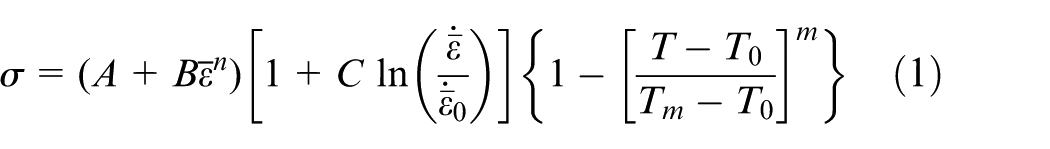
where A is the material initial yield stress, B is the strain hardening coefficient, C is the strain rate coefficient, m is the temperature exponential term, n is the strain exponential term,
During machining process, the primary shear zone undergoes large strain and high strain rate. Dynamic recrystallization has been reported on the shear band from experimental study. 23 The JMAK recrystallization model can be used to describe the effect. The initial JMAK model is developed for use in modeling of isothermal conditions. In order to follow the JMAK model in machining, a random distribution of nucleation sites and grain growth are assumed here. The initial average grain size is d0. The explicit calculation of the dynamic recrystallization process can be found in a previous study. 24 The recrystallized volume fraction is determined to be Xdrex. From grain growth and nucleation, the dynamically recrystallized average grain size can be calculated as ddrex. Using a rule of mixtures approached, the average grain size after recrystallization can be easily obtained as

For crystalline material, reduction in the average grain size can help to increase material yield stress as described by the Hall–Petch equation. To simplify the flow stress model, the grain size is assumed to be effecting only the initial yield stress of the material, which is the parameter A in the JC model. So, the Hall–Petch relation can be written as

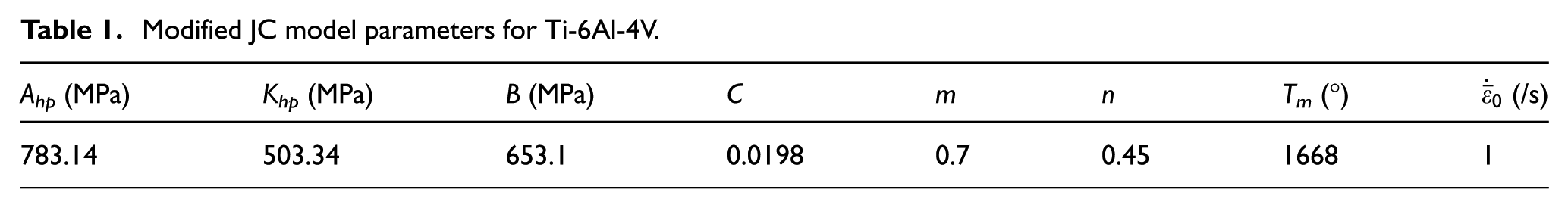
where Ahp and Khp are material constants to be determined. The initial average grain size of the raw Ti-6Al-4V material is determined to be 2.28 µm, as shown in Figure 1. With a linear regression analysis against the experimental data provided by Picu and Majorell, 25 the Ahp and Khp parameters could be obtained as 783.14 and 503.34 MPa, respectively. The modified JC parameters of Ti-6Al-4V are listed in Table 1.
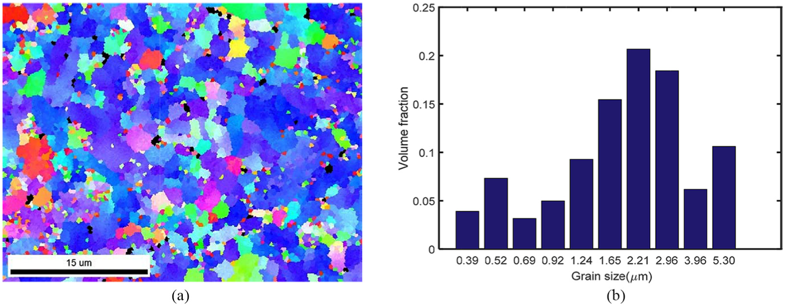
EBSD image of the raw material microstructure state: (a) the grain size distribution of the α phase and (b) the histogram of the α phase grain size.
Modified JC model parameters for Ti-6Al-4V.
Residual stress model
During the machining process, the residual stress comes from the severe thermo-mechanical loading and material microstructural state change. Heat generated in the machining process can have significant influence on the residual stress profile. The heat comes from the primary shear zone and tertiary shear zone between the tool and workpiece. To calculate the temperature field induced by the deformation in the shear zone, an imaginary moving heat source approach is used, 26 as shown in Figure 2. The temperature rises in the workpiece due to shear deformation is the combined effects from the shear heat source and imaginary heat source, which can be obtained as
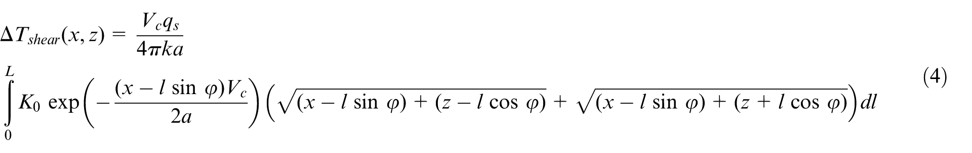
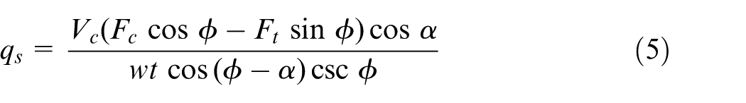
where L is the shear length, L = t/sin ϕ, ϕ is the shear angle, t is undeformed chip thickness, ϕ = φ − π/2, Vc is the cutting speed, a is the workpiece thermal diffusivity, k is workpiece thermal conductivity, and K0 is the modified second Bessel function. The average shear stress in the shear zone can be approximated as
Heat transfer model in the shear zone.
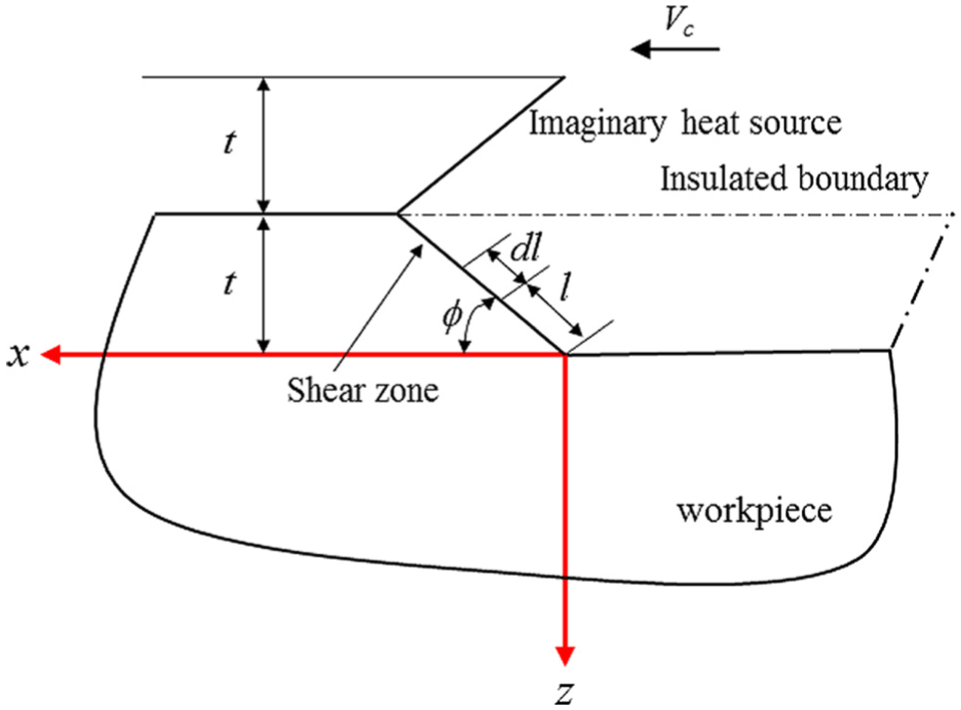
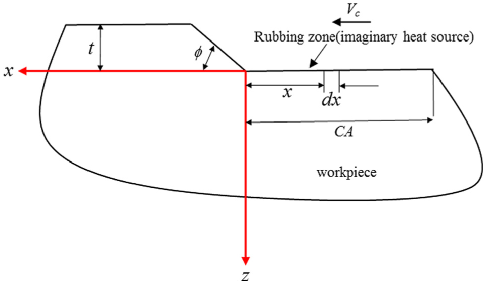
With a similar method, a moving heat source can be used to represent the generated heat in the rubbing zone, as shown in Figure 3. To satisfy the insulated boundary condition on the workpiece surface, an imaginary heat source is imposed as coinciding with the original rubbing heat generation. The temperature rise induced by the tool–workpiece rubbing can be calculated as
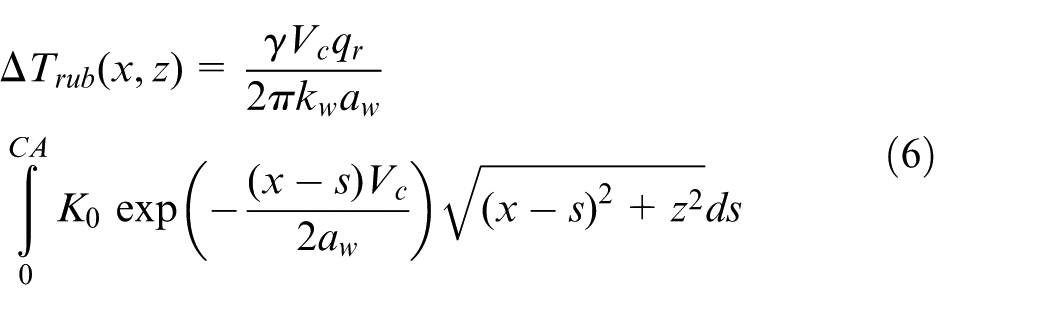
where CA is the work-dead zone interface length which is calculated using Waldorf et al.’s 27 slip line model. γ is heat partition coefficient that transferred to the workpiece. According to Barber, the heat partition could be calculated as
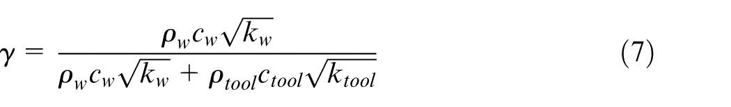
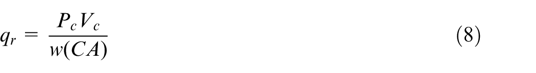
where the subscript ρw, cw, and kw are the workpiece material density, heat capacity, and thermal diffusivity, respectively. ρw, cw, and kw are corresponding the tool properties. The rubbing stress qr is determined from the plowing force in the cutting direction Pc as
Heat transfer model in the tool–workpiece tertiary shear zone.
The plowing force Pc can be calculated from traditional cutting mechanics, 28 and w is the width of cut. The total temperature rise in the workpiece can be obtained by superimposing the two temperature effects from rubbing and shear as

In the two-dimensional orthogonal turning process, the machining forces can be obtained from Oxley’s contact mechanics theory, which has been investigated in a previous paper. 29 The equivalent normal stress field p1(s) and shear stress q1(s) are used to represent the mechanical loading in the rubbing zone, as shown in Figure 4. Similarly, p2(s) and q2(s) are used to represent loading in the shear zone. The residual stress in the machining process is determined from the stress history of the workpiece. In the orthogonal turning, the coordinate system is established in Figure 5. With a plane strain assumption, the stress in the y-direction is assumed to be zero. A simple rolling/sliding contact is assumed between the cutting tool and the workpiece. The equivalent stress loads from the tool–workpiece interface and shear zone are accounted for in the stress field calculation. By integrating the stress load with a Boussinesq integration scheme, the stress field can be described as 9
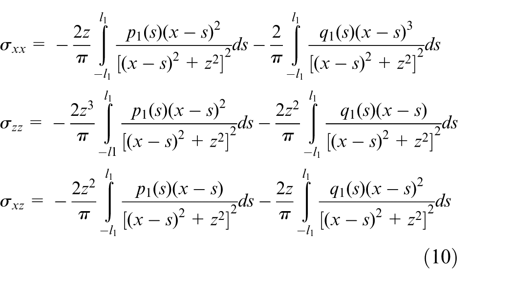
where l1 is the half tool–workpiece contact length in the rubbing area. The normal p1(s) stress load and shear stress load could be determined from the thrust force, Ft, and cutting force, Fc, respectively. A similar strategy can be used for the stress field calculation induced by the shear zone using p2(s) and q2(s). 30 In order to superimpose the two stress fields, the ϕ angle clockwise rotation is required to translate the shear zone stress into the x/y coordinate system.
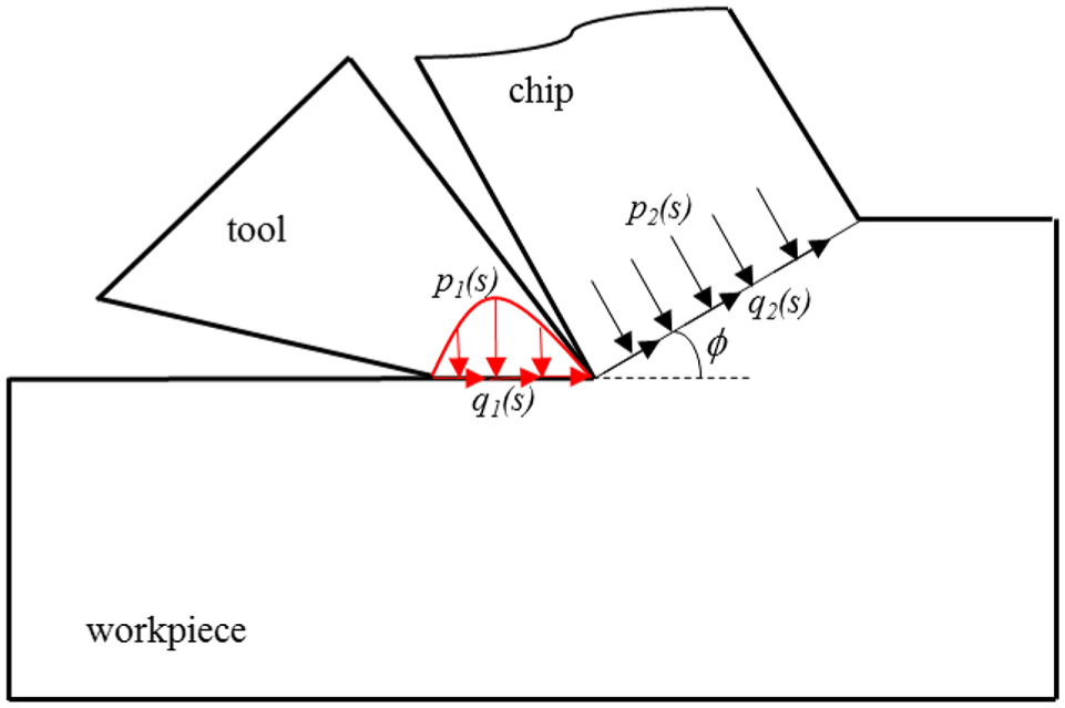
Simplified load for stress field calculation.
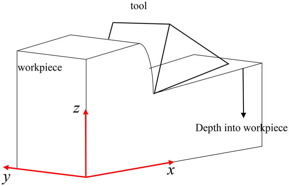
Schematic diagram showing the residual stress coordinate system.
The hybrid McDowell algorithm 31 is used for the residual stress calculation. Both the elastic and plastic deformations are involved. The modified JC model is used for the yield stress calculation. The yield surface is described by a Von Mises yield criterion by accounting for the kinematic hardening
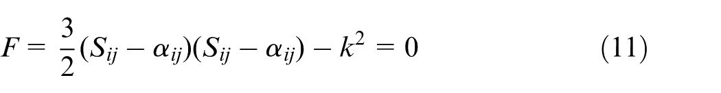
where Sij is the deviatoric stress and αij is the deviatoric back stress. The deviatoric back stress evolution is defined as

where < > is the Macaulay bracket as, <x> = 0.5(x + |x|); nij is the unit normal vector pointing outward the yield surface
A blending function is defined as
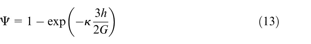
where κ is a constant, h is the modulus, and G is the shear elastic modulus. In an elastic/plastic loading of the machining process, the strain rate in the cutting direction can be obtained as
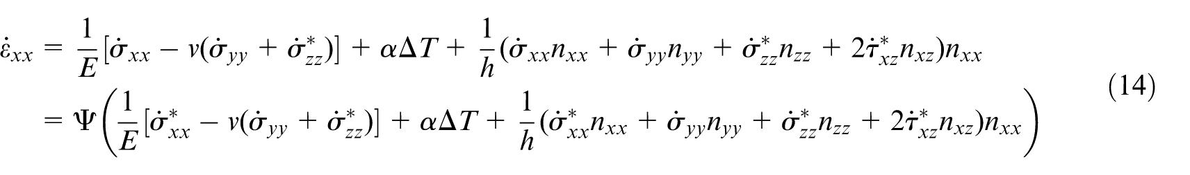
where α is the thermal expansion coefficient. By assuming a plane strain condition, the strain rate in the cutting transverse direction can be similarly expressed as
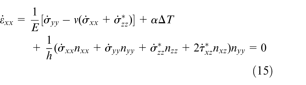
Equations (13) and (14) are simultaneously solved to get the stress rate increments
Results and discussion
Considering the calculated machining forces and temperature field from equation (9), the elastic stress field could be obtained from equation (10). By integrating the stress field along the loading path with equations (14) and (15), the residual stress σxx and σzz were obtained. At a feed rate of 0.1 mm/rev, cutting speed of 26.4 m/min, depth of cut of 0.1 mm, tool rake angle of 0°, and clearance angle of 7°. The tool edge radius is 8 µm. Since in the machining process, the process parameters and tool configuration are kept the same. The residual stress on any point at the same depth is the same. The measurement is randomly picked from the data point on the machined surface. By removing the layer with electrochemical polishing, the residual stress underneath the surface could be measured. The predicted residual stress as a function of depth into the workpiece is plotted in Figure 6. Also, the temperature contour on the workpiece near the workpiece–tool interface is shown in Figure 6(b). The maximum predicted temperature goes up to around 500 °C. The stress is plotted in both cutting direction and transverse direction. Large tensile residual stress is predicted on the machined workpiece surface. The magnitude of the tensile residual stress sharply decreases to zero as the depth into the part increases and the stress state changes tensile to compressive. Around the depth of 15 µm, the compressive residual stress reaches a maximum value. After that, the magnitude of the compressive residual stress slowly decreases to zero at a depth around 0.1 mm. Under machining conditions used for this model, the resulting residual stress affected depth is around 100 µm. The general trend of the residual stress profile on the machining-induced residual stress is captured by the model as comparison with the experimental measurements from Ratchev et al. 32 However, large discrepancy was found in surface residual stress predictions where the model predicts tensile residual stress, but the experimental measurements show the compressive residual stress. In most of the residual stress measurement on machining, the surface oxidation could be a very important reason that will contribute to the error. From the modeling side, the residual stress generation in the machining mainly comes from three sources, the un-uniform plastic deformation, the existing of the temperature gradient, and the material phase transformation–induced residual stress. In the current model, the author only considers the first two sources. The phase transformation effect on the residual stress is ignored. Specifically, for the Ti-6Al-4V material, the α to β phase transformation would induce the volume increase. This will result in a more compressive residual stress on the surface. This would further explain the fact that the model prediction tends to be more tensile than the prediction. Ramesh and Melkote 33 introduced a residual stress prediction model that accounts for the martensitic phase transformation effect. More advanced model would be required to capture those complicated microstructure evolution effect for the residual stress prediction. The peak compressive residual stress value shows 8.03% error in the cutting direction and 4.36% error in the transverse direction.
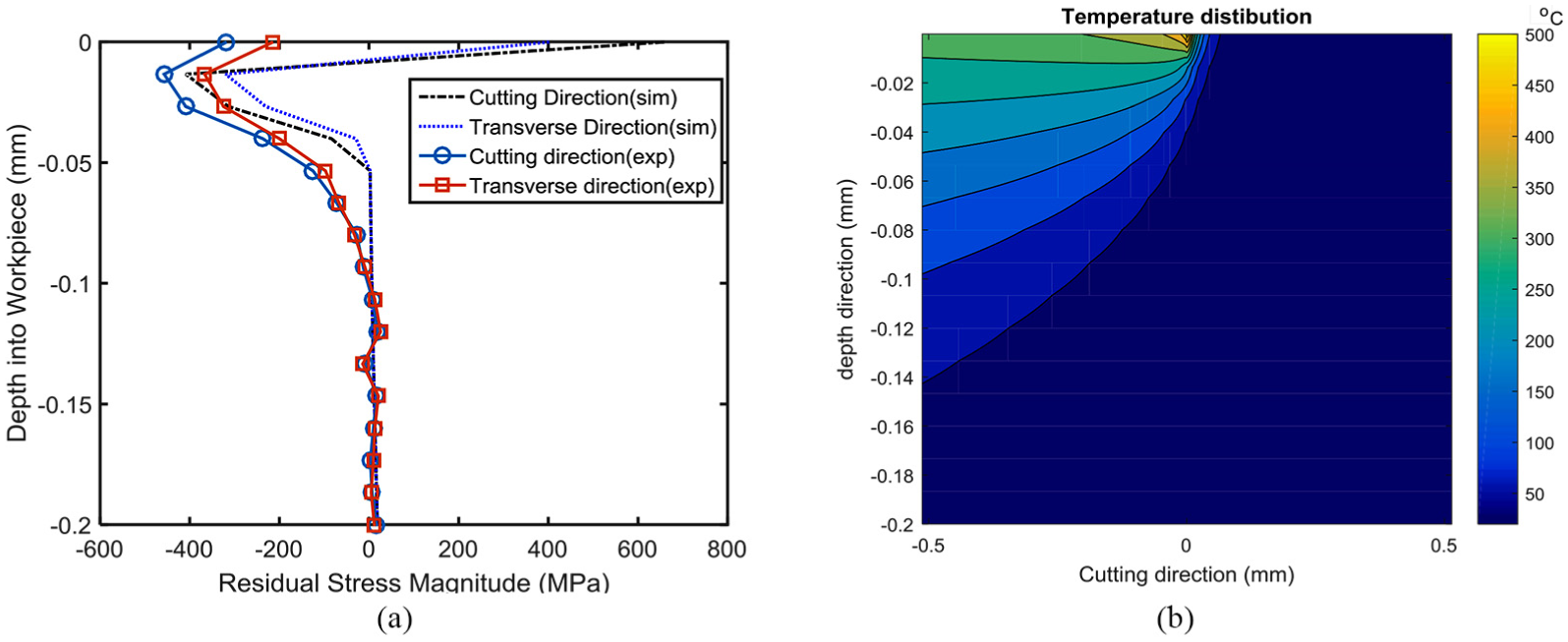
Prediction and measured residual stress (a) and workpiece temperature distribution (b) at a feed rate of 100 µm/rev, cutting speed of 26.4 m/min, and depth of cut of 100 µm.
A predicted residual stress profile using a cut depth of 0.5 mm is plotted in Figure 7(a). On the surface, the predicted residual stresses are still tensile in both transverse and cutting directions. Compared to the depth of cut at 0.1 mm, the residual stress in the transverse direction are less tensile when the depth of cut increases. The residual stress–affected depth is increased slightly, which is around 0.15 mm. The prediction closely follows experimental measurements. The maximum predicted temperature is still around 500 °C. The peak values of compressive residual stress from the model prediction are 28.32% and 1.49% in the transverse direction. For the residual stress prediction model, the prediction error is at an acceptable level.
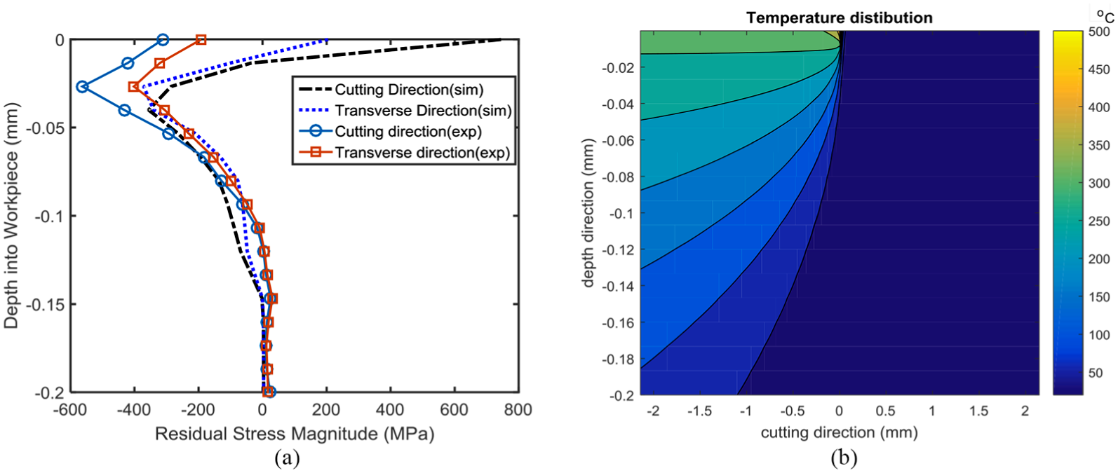
Predicted and measured residual stress (a) and temperature distribution on the workpiece (b) at feed rate of 100 µm/rev, cutting speed of 26.4 m/min, and depth of cut of 500 µm.
For a further validation test, the AISI 4130 steel is used as a case study. A hollow cylindrical sample is used for the face turning. The rake angle is selected to be 5°. A constant width of cut is equal to the wall thickness of 4.775 mm. The cutting speed is 1.049 m/s. Depth of cut is 0.0508 mm. The experimental data are obtained from the work of Ji et al. 34 The JMAK model parameters of AISI 4130 and modified JC model are from a previous work. 35 The predicted residual stress is plotted against the experimental data for comparison, as shown in Figure 8. The tensile residual stresses in both directions are accurately predicted. However, there exists obvious error in the peak value of the compressive residual stress, which are 53.26% in the cutting direction and 33.89% in the transverse direction.
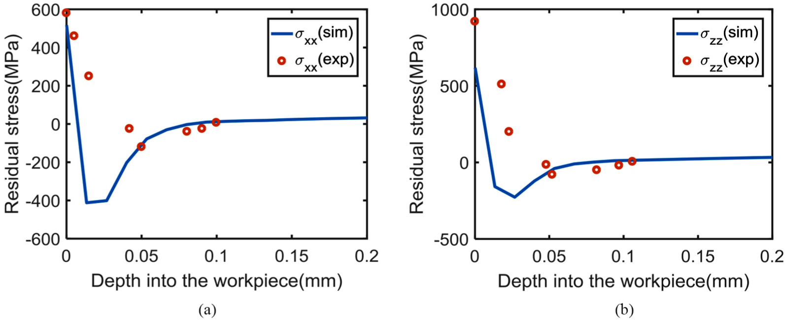
The machining induced residual stress in the cutting direction σxx (a) and transverse direction σzz (b) at the cutting speed of 1.049 m/s and depth of cut of 0.0508 mm.
For the parametric study for the effect of different machining process parameters on the residual stress of Ti-6Al-4V, three more parametric studies are conducted. At a cutting speed of 0.5 m/s, depth of cut 0.1524 mm, and tool rake angle of 8°, the predicted residual stress as a function of depth into the workpiece is plotted in Figure 9. The stress is plotted in both cutting direction and transverse direction. A compressive residual stress is found on the machined workpiece surface. As the depth into the workpiece increases, the magnitude of the compressive residual stress further increases. Around a depth of 25 µm, the residual stress reaches it maximum value. After that, the magnitude of the compressive residual stress decreases. At a certain point, the compressive residual stress switches to tensile. The magnitude of the tensile stress is close to zero. The residual stress affected depth is around 75 µm beneath the machined surface.
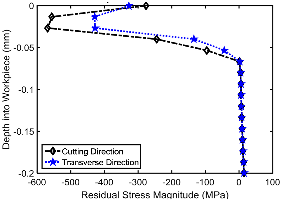
Residual stress prediction with a cutting speed of 0.5 m/s, depth of cut of 0.1524 mm, and rake angle of 15°.
By decreasing the rake angle from 15° to 8°, the predicted residual stress profile is plotted in Figure 10. The residual stress in both directions is still compressive but the magnitude of the compressive residual stress is significantly decreased. A similar trend is followed as with a rake angle of 15°. One more case is conducted by increasing the depth of cut to 0.3048 mm, as shown in Figure 11. Compared with the depth of cut of 0.1524 mm, the magnitude of the compressive residual stress has sharp decrease on the machined workpiece surface. The largest value of the compressive residual stress is slightly increased. The residual stress–affected depth also increases up to around 100 µm. By reducing the rake angle from 15° to 8°, the surface magnitude of the compressive residual stress has sharp decrease, as shown in Figures 9 and 10. The smaller rake angle would result in more heat generation. This presence of the thermal effect would lead to a more tensile residual stress profile on the surface. Similarly, the increasing depth of cut also results in a more tensile residual stress profile on the machined surface, as compared by Figures 9 and 11.
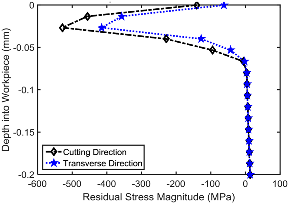
Residual stress prediction with a cutting speed of 0.5 m/s, depth of cut of 0.1524 mm, and rake angle of 8°.
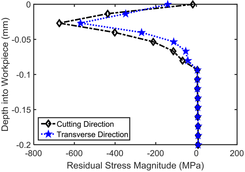
Residual stress prediction with a cutting speed 0.5 m/s, depth of cut of 0.3048 mm, and rake angle of 15°.
Conclusion
By accounting for the dynamic recrystallization–induced grain size evolution, an analytical model is proposed for the residual stress prediction in the orthogonal turning of Ti-6Al-4V material. The material grain size evolution in the dynamic recrystallization process is explicitly calculated in the turning process. A modified material flow stress model is developed by considering the grain size effect with the Hall–Petch relation. With the classic Oxley’s contact mechanics theory, the mechanical loading and thermal loading are obtained. The hybrid McDowell algorithm is used for the residual stress prediction. Validation tests are conducted between the predicted residual stress and experimental measurement. Good agreements are found between model prediction and experimental data. With the validated analytical model, the residual stress profile on the machinated workpiece is predicted. The effects of tool rake angle and depth of cut on residual stress profile are investigated. The proposed analytical model provides a more fundamental understanding of the effects material dynamic recrystallization on the cutting mechanics.
Footnotes
Declaration of conflicting interests
The author(s) declared no potential conflicts of interest with respect to the research, authorship, and/or publication of this article.
Funding
The author(s) disclosed receipt of the following financial support for the research, authorship, and/or publication of this article: Financial support from the university strategic program of manufacturing research institute of Georgia Institute of Technology is deeply appreciated.