
Abstract
Time-varying process models for micro-machining processes are important as they aid in control of machining parameters. In this research, a state-space-based process model for the temperature and strain generated near the cutting edge of the tool tip is identified using system identification approach. Fiber Bragg grating sensors were placed rigidly near the cutting edge of the tool tip in a micro-turning setup. Subsequently, micro-turning operations were carried out on aluminum and mild steel. The computer numerically controlled program was such that the machining parameters (feed velocity, depth of cut and RPM) change with machining time. The time-varying machining parameters act as inputs to the model, and the dynamic values of strain and temperature serve as model output. A state-space model was generated using the experimental data. Subsequently, a Kalman filter was used to intelligently predict the values of strain and temperature at the cutting edge of tool tip in advance using the model parameters identified by state-space modeling. Experimental results confirm that the time-varying model and the Kalman filter proposed in this research are effective in predicting the strain and temperature in advance with high accuracy. The maximum error in prediction of temperature was 0.4 °C, whereas for strain prediction, the maximum error was 0.3µ∈.
Introduction
Micro-turning is a micro-scale material removal process in which a stationary cutting tool with nose radius in microns is fed against a rotating workpiece. A small volume of material is removed from the workpiece in this process. The physics of material removal is dependent on a number of factors such as machining parameters, experimental conditions, effect of micro-structures and material properties.1,2 The dependence of the tool–work conditions during and post machining on multiple parameters makes the machining physics complex. Physical quantities such as tool strain, temperature, machining vibration and cutting forces change the machining physics. For instance, tool strain leads to machining inaccuracies and extensive tool breakage due to miniature size of the tool and low machine stiffness of machining setup, whereas tool–work interfacial temperature damages the surface integrity of the machined profile. This further creates trouble in appropriate condition monitoring and control of micro-machines. Appropriate time-varying process models for tool strain and temperature variations with machining parameters along with their knowledge in advance is desired for control and condition monitoring of micro-machines. 3 Intelligent assessment of the strain and temperature near to the cutting edge of tool tip in advance employing process model can aid in prevention of tool breakage and enhancement of surface integrity using condition monitoring methods. 4
In the past, a number of researchers have proposed process models for conventional cutting processes. These include very popular ones such as Merchant’s 5 model, Lee-Shafer model, 6 Hill’s 7 model and Fan and Dewhurst’s 8 model. All of these models for conventional machining process had a few limitations. In Merchant’s model, the state of the stress ahead of the work during machining was not considered. The Lee-Shafer model targeted to eradicate the limitations; however, they considered that the work material was rigidly perfect solid. The above models were static and the modeling parameters were dependent on the tool geometry. In micro-scale cutting processes, tool geometry cannot be accurately determined due to micro-structural variations in tool and the work. Dynamic models are required for appropriate process control. Further none of these models considered the effect of work-hardening and the size effect which are prime factors when the depth of cut for a cutting process approaches the nose radius of the tool and is prevalent in micro-scale cutting processes. Recently, Silva et al. 9 conducted experiments to validate the proposed models for conventional machining at micro-scale and found that the model outputs for conventional and micro-machining processes varied.
The stated models were steady-state models where dynamic variations in various physical parameters were not considered. Piotrowska et al. 10 proposed a force-based dynamic model for micro-turning which considered the machining stiffness and material constants of the machine. They validated their force model with experimentally procured machining force data from a micro-turning machine using a dynamometer. The force-based dynamic model though was effective; however, taking the cutting force only into consideration cannot provide a comprehensive insight of a machining model. This is because the dynamometer is placed far away from the tool–work interface. So, the force measured will contain noise components due to limited stiffness of tool holder, 11 mounting screws and so on. Furthermore, the force which is measured is not a primary physical parameter generated at the tool–work interface. At the tool–work interface, shearing/plowing of the material occurs which results in tool strain. The friction leads to temperature enhancement. The physics of contact-based micro-material removal processes is dependent on these two parameters as the strain and temperature lead to micro-structural variations during the process operations. Thus, measuring the primary quantities (strain and temperature) and building up a dynamic mathematical model for process control of the machine is essential for proper process control.
Measurement of interfacial tool–work strain and temperature in micro-cutting is a daunting task. This is due to very limited footprint of the tool tip. Thermocouple-based temperature measurement 12 and use of strain gauge for measurement of strain 13 at the cutting edge of the tool tip used by several researchers for conventional cutting does not deem effective for micro-cutting case. Further using a number of different sensors for the measurement of different parameters leads to higher noise and errors in measurement setup. Non-contact-based temperature measurement technique 14 such as thermal cameras is ineffective for micro-machining as it is difficult to focus on a miniature area. Furthermore, measurement of both strain and temperature within a limited footprint employing sensors of similar type is difficult. In order to mitigate these problems, the authors used fiber Bragg grating (FBG) sensor for measurement of tool-tip strain and temperature. Very recently, FBG sensor was used for temperature measurement at the cutting edge of tool tip in micro-turning operation and to establish a relationship between tool-tip temperature and surface integrity of the machined profile. 15 However, measurement of strain and temperature near to the cutting edge of the tool tip simultaneously with time-varying machine parameters for system modeling and process monitoring has never been conducted.
In this research, the strain and temperature at the cutting edge of the tool tip with time-varying machine parameters (feed velocity, depth of cut and spindle RPM) is measured. A stochastic-deterministic state-space model is identified using the inputs and the outputs of the experiments. N4SID (numerical algorithms for subspace state-space system identification) 16 based method was used for state-space-based system identification. The system parameters were fed to a Kalman filter which predicts the strain and temperature near to the cutting edge of the tool tip ahead of machining time. The details of the methodology are presented in the subsequent section.
Methodology
The paradigm for process modeling and prediction of strain and temperature ahead of time near to the cutting edge of tool tip is conducted in two steps:
State-space modeling of micro-turning using N4SID algorithm;
Feeding the state-space parameters to a Kalman filter for prediction of strain and temperature in advance.
These steps are elaborated in detail in the subsequent subsections. The methodology is presented in the block diagram as shown in Figure 1.
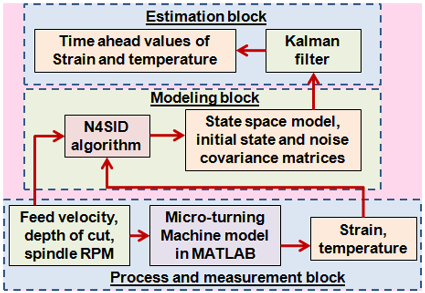
Methodology for state-space modeling and time-ahead strain and temperature prediction for micro-turning tool.
System identification using N4SID algorithm
System identification for state-space model generation can be conducted using a myriad of paradigms such as Ho-Kalman algorithm, 17 regression, 18 prediction error method 19 and subspace-based methods. In this work, subspace-based N4SID algorithm was used for system identification as this paradigm can easily be applied for single-input single-output (SISO) and multi-input multi-output (MIMO) systems. 20 Furthermore, the convergence rate for such algorithm is high as it is not iterative and hence is faster than other system identification methods. In this work, we use the asymptotically biased combined deterministic-stochastic identification algorithm as it is simpler and poses lesser computation load as compared to asymptotically unbiased algorithm.
The strain and temperature near to the cutting edge of the tool tip procured using the FBG sensor acts as the model outputs and the time-varying machining parameters (feed velocity, depth of cut and RPM) act as model inputs. The envisaged model is a three-input and two-output system. A code corresponding to N4SID algorithm was generated in MATLAB. The details of the mathematical operations can be found in the reference. 21 The algorithm computes the state-space model for the given inputs and outputs of a MIMO system as stated in equations (1) and (2)


where A, B, C and D are the system matrix, input matrix, output matrix and feedforward matrix, respectively; x is the state vector; u is the input vector and y is the output vector; e(k) is the model residual and K is the Kalman gain; Ke(k) is the process noise sequence which can be denoted by w(k) having covariance Qs and e(k) is the measurement noise which can be denoted by v(k) having covariance Rs; and Ss is the cross covariance of process and measurement noise.
The steps for the N4SID algorithm are as follows. Set inputs {um(k), m = 1, …, M} and outputs {yl(k), l = 1, …, L}, system order: n, number of rows in Hankel matrices: 2i. (i > n).
Number of columns in block Hankel matrix, j = s − 2×i+1, where s is the total number of samples.
Generate the block Hankel matrices for inputs (u) and outputs (y).
Compute QR decomposition of {u y}T. Generate a matrix R.
Calculate the sub-matrices Rf, Rp and Ru.
Calculate the oblique projection (Oi) for matrix R.
Compute the singular value decomposition (SVD) for the matrix Oi.
Calculate the second oblique projections by repeating steps 5 and 6. We get matrix Oi as in step 6 but shifted by one foreword value due to second projection denoted by Oi+1.
Determine the state sequences Xi and Xi+1.
Determine the state matrices (A, B, C and D) using least-squares method.
Calculate the residuals and the noise covariances (Rs, Ss and Qs), where Qs is the process noise covariance, Rs is the measurement noise covariance and Ss is the cross covariance of the noise.
Solve the Riccati equation to get error covariance of state estimate P and the gain K.
The values of A, B, C, D, K, P, Rs, Ss and Qs along with the initial state matrix give us the state of the system when modeled using the set of inputs and outputs. It is natural that the generated model will work if the inputs to the model lie within the range. Usually, for every computer numerically controlled (CNC) machine, a set of conditions is prescribed by manufacturers for machining a particular material and hence the system model is useful for a specific material. The obtained values are fed to a Kalman filter for prediction of strain and temperature in advance. The methodology for prediction of time-ahead values using Kalman filter is explained in the next section.
Kalman filter for time-ahead temperature and strain prediction
The Kalman filter is a linear quadratic estimator (LQE) which estimates the time-ahead state of a system, provided the state-space model, noise covariances, initial state of the system and the initial error covariance of the state is known. The Kalman filter is the best linear least mean square estimator if the process and measurement noise are white. 22 In this research, the Kalman filter is used to predict the time-ahead state of the system where the state-space model parameters act as input to the Kalman filter. In machining operations where the process and measurement are related, there remains a possibility of existence of correlation between process and measurement noise. Furthermore, the effect of feedthrough matrix (D) is to be taken into consideration while designing a Kalman filter.
The aforementioned problems are mitigated employing the following measures:
1. For cross-correlated process and measurement noise, the state-space equations are reformulated so that the noise sequences do not correlate with each other. Equation (1) can be reformulated as equation (3) where the noise is non-correlated 23

where
2. To consider the effect of matrix D, the Kalman filter equations are reformulated for a system with direct feedthrough.
The Kalman filter projects the state of the system in two phases, namely, estimation (update) phase and prediction (propagation) phase. In the presence of direct feedthrough, the Kalman filter equations are given by equations (4)–(8). 24
Estimation equations


Prediction equations


The subscripts k|k and k|k − 1 denote the estimate of the particular variable after and before the original measurement, respectively.
The output at (k+1)th time instant is given by equation (9)

where Yk+1 contains one step ahead predicted outputs (strain and temperature). A MATLAB code corresponding to state-space augmentation and Kalman filter was generated.
Experiments conducted
The experimental setup consists of an indigenously developed three-axis CNC micro-turning machine in which FBG sensors are attached rigidly at the cutting edge of the tool tip. The details of the experimental setup and the method to procure the strain and temperature data during machining operations is stated next.
Experimental setup
The experimental setup consists of a three-axis system for micro-turning operations which houses three-axis motion stages supplied by Holmarc Company (Model no. MTS90115-2) driven by stepper motors. An indigenous driver-controller system is designed for driving the setup. The spindle used in the system can rotate at a maximum speed of 7000 RPM. The tool used for machining was a turning insert procured from Sandvik Coromant (Part no. MAFL3010 1025). The rake angle (γ) of the tool was 0°, the clearance angle (α) was 9° and the tool nose radius (r∈) was 100 µm. The tool had a notch near to the cutting edge where the FBG sensors could be easily accommodated. Micro-turning operations were conducted for aluminum and mild steel. Before the setup for measurement of strain and temperature is explained, a brief explanation about working principle of FBG is stated next.
FBG sensor works on the principle of Fresnel’s diffraction. It consists of an optical fiber with spatial modulation of refractive index. This modulation causes a specific wavelength of broadband light incident on the gratings to get reflected back. Variations in temperature or strain result in the shift in wavelength of reflected light. The wavelength shift is measured using an interrogation circuitry to get the values of strain and temperature. 25 FBG sensors possess cross sensitivity to strain and temperature. Elimination of cross sensitivity can be conducted by various methods; however, the simplest being the use of two FBGs of different strain and temperature sensitivities. 26 This paradigm is used to measure strain and temperature in this research.
Measurement of temperature near to the cutting edge of the tool tip was conducted using a standard FBG-based temperature probe (Micron optics OS4210). FBG-based standard strain sensors are larger, and it is difficult to accommodate them near the tool tip unlike in the case of temperature probe which is miniature in size. The problem was alleviated using a Germanium-doped bare FBG sensor pre-calibrated using a standard FBG strain sensor (OS3110) and temperature sensor (OS4210). The strain sensitivity of OS3100 and the temperature sensitivity of OS4210 are 1.4 pm/µ∈ and 10 pm/°C, respectively. The fabricated FBG operates at 1517 nm nominal wavelength. The strain and temperature sensitivities for the fabricated FBG were found to be 1.137 pm/µ∈ and 11.347 pm/°C, respectively. The sensors were attached rigidly in the tool notch near to the cutting edge using Araldite adhesive. It is not possible to place the sensors directly at the cutting edge as the chip flow and the tool–work interactions may damage the sensor attachment. NI-based FBG interrogator (PXIe 4844) was used for sensor interrogation. The interrogator measures the shift in nominal wavelength for the FBG sensors. Strain and temperature values were obtained from the wavelength shifts of the FBG sensors using equations (10) and (11)
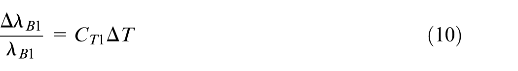
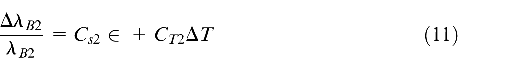
where the subscript “1” represents the FBG temperature sensor (OS4210) and the subscript “2” represents the bare FBG sensor which has both strain and temperature sensitivities; λB is the nominal wavelength; ΔλB is the shift in nominal wavelength; CT and Cs are the temperature and the strain sensitivities, respectively; and ε and ΔT are the strain and the temperature, respectively. The experimental setup is shown in Figure 2.
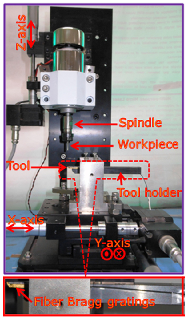
Experimental setup for measurement of strain and temperature using FBG sensors in micro-turning.
The image of the micro-turning tool is shown in Figure 3(a), and the magnified image of the tool is shown in Figure 3(b). The magnified image was captured using Olympus BX51M microscope with Moticam 580 camera attachment, and the distance between the cutting edge of the tool tip and the FBG sensors was measured using software available with the microscope package Motic Images plus 2.0. The distance between the cutting edge of the tool tip and the FBG sensors in the stated experimental setup was found to be 126 µm.
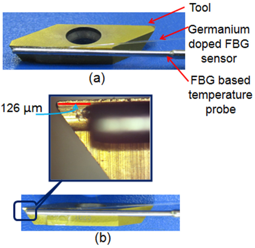
Images of the tool (a) with the tool sensor attachment details and (b) magnified image of the tool sensor interface as seen under microscope.
Experimental method
Micro-turning operations were carried out on aluminum and mild steel. For generation of state-space model, the machining parameters varied with time at an interval of 1 s, and the strain and temperature at the cutting edge of the tool tip were recorded. A total of 64 combinations of machining parameters using 4 different values of sample data (feed velocity, RPM and depth of cut each) were used for the modeling experiments and each of these materials was machined for generation of state-space models. The sample dataset for generation of machining conditions is stated in Table 1.
Sample dataset of machining parameters for state-space modeling.
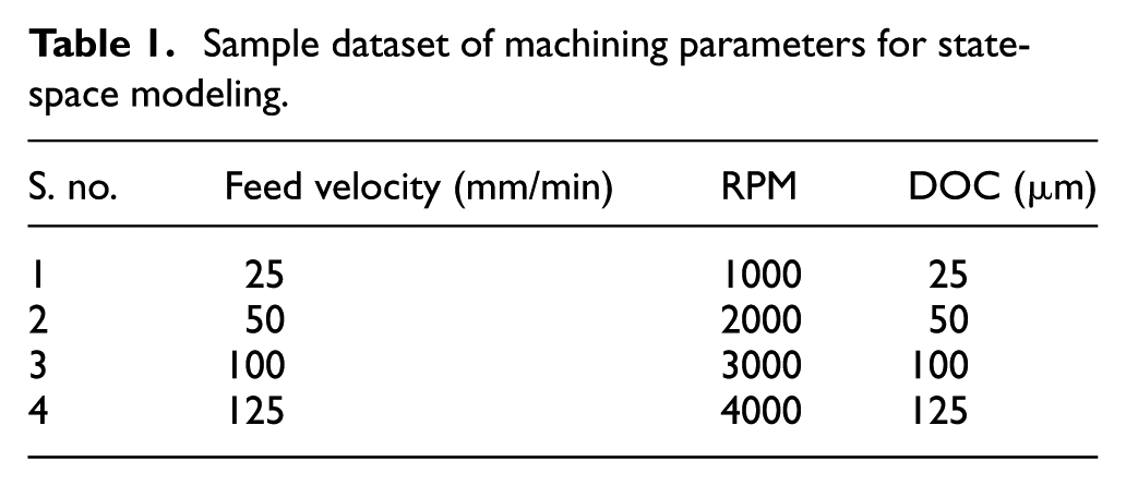
The strain and temperature data measured at the cutting edge of the tool tip were recorded which act as model outputs, and the experimental conditions (feed velocity, RPM and DOC) act as model inputs. A state-space model is obtained using the N4SID algorithm as stated earlier. The order (n) was set to 2 and the value of i was set to 3. These values were selected based on iterative trials so that the state-space parameters are realistic (i.e. full-rank matrices).
After obtaining the state-space models for the three different materials, the materials were machined for different set of conditions in order to facilitate the efficacy of the Kalman filter in one-step-ahead prediction of strain and temperature. The experimental conditions are set such that they lie within the maxima–minima spectrum of the modeling conditions in Table 1 (25 to 125 mm/min feed, 1000 to 4000 RPM and 25 to 125 µm DOC). The experimental conditions consisted of 27 combinations derived from three different values of feed velocity, RPM and depth of cut each, varying every second. The sample data are presented in Table 2.
Sample data for prediction of time-ahead values using Kalman filter.
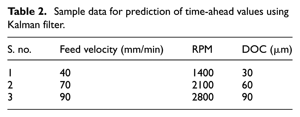
The Kalman filter depicted in section “Methodology” was used to predict the time-ahead values of strain and temperature during micro-turning operations with the machining conditions as stated in Table 2.
The chips generated during micro-turning operations for aluminum and mild steel for the machining conditions stated in Table 2 were collected and were visualized under a microscope (Olympus BX51M microscope with Moticam 580 camera attachment). The size of the chips was measured using Motic Images 2.0 software available with the microscope package.
Results
The strain and temperature values versus time recorded at the cutting edge of the tool tip during machining operations with the machining conditions as stated in Table 1 are shown in Figure 4.
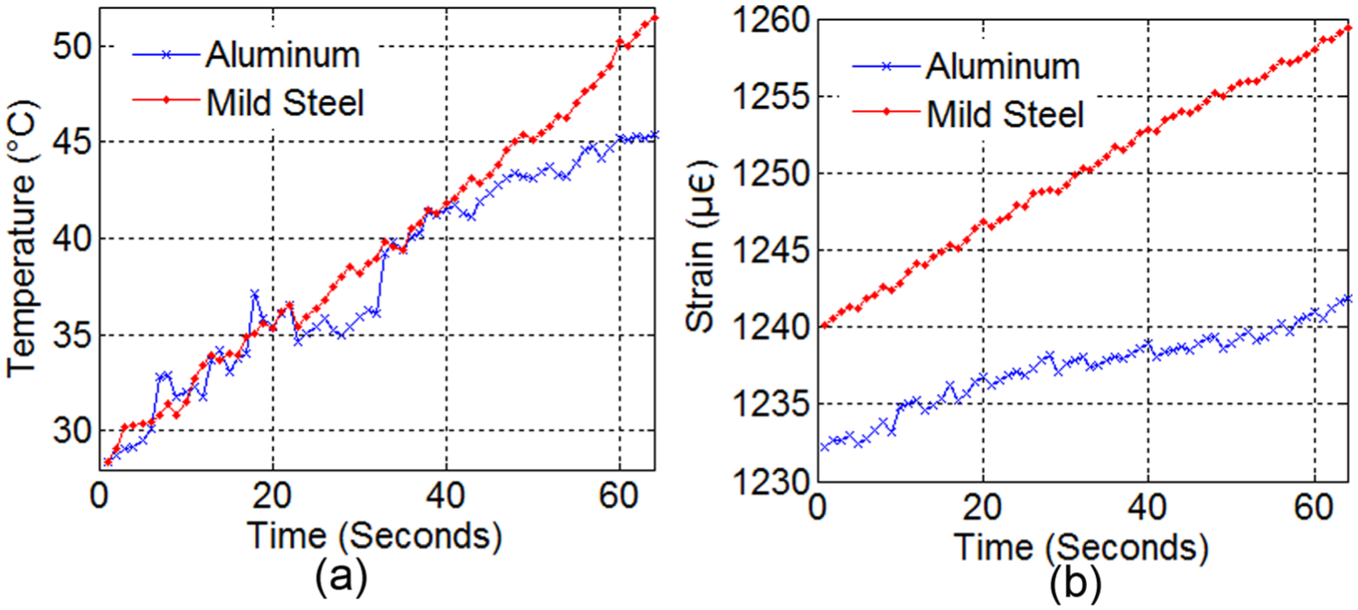
(a) Temperature variations with machining time and (b) strain variations with machining time
The state-space parameters extracted from the N4SID algorithm for the state-space equations (1) and (2) are system matrix (A) with values
The measured values of strain and temperature and the time-ahead values predicted using Kalman filter for the machining conditions as depicted in Table 2 are shown in Figure 5.
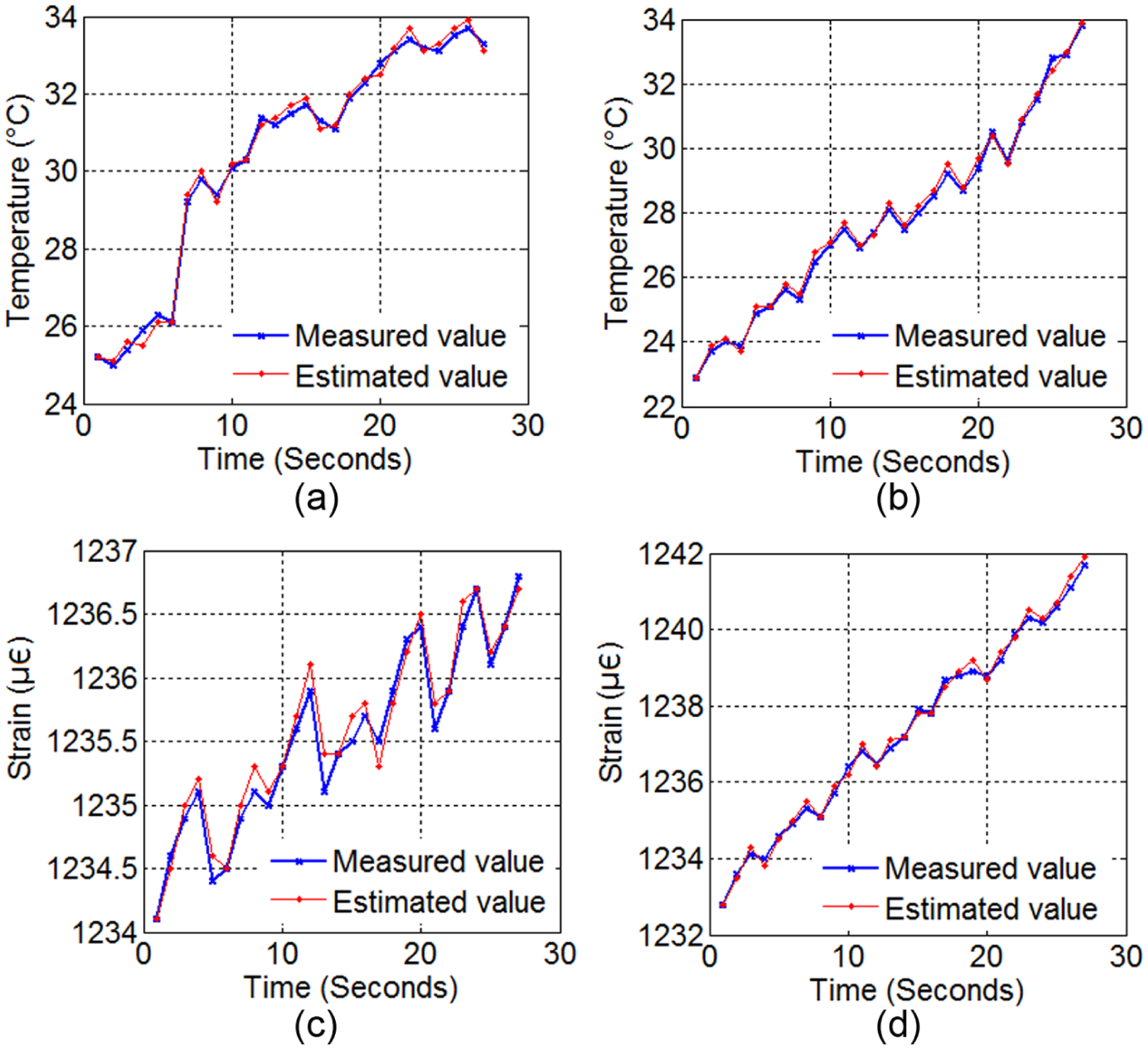
Measured and predicted values of (a) temperature while machining aluminum, (b) temperature while mild steel, (c) strain while machining aluminum and (d) strain while machining mild steel
The prediction errors in strain and temperature while machining aluminum and mild steel are depicted in Figure 6.
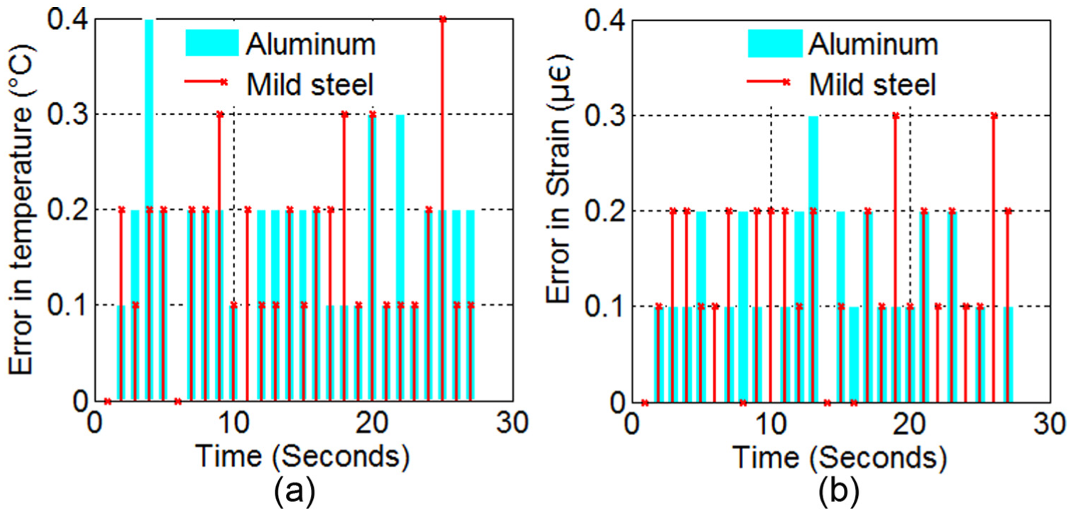
Errors in (a) temperature prediction and (b) strain prediction while machining aluminum and mild steel
The chip morphology and chip size generated while performing the experiments are shown in Figure 7.
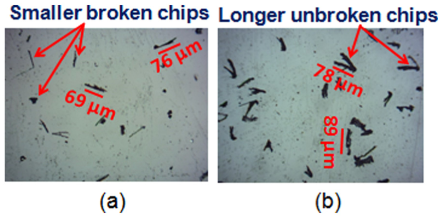
Microscopic images of chips collected during machining of (a) aluminum and (b) mild steel.
Discussions
Following inferences could be drawn from the experiments, model and prediction of time-ahead values of strain and temperature employing Kalman filter.
The rate of rise in temperature while machining mild steel is higher than aluminum (Figure 4(a)). This is due to lower thermal conductivity of mild steel than aluminum. While machining, mild steel generates longer, unbroken chips which delay the heat dissipation from the cutting zone.
The strain induced while machining mild steel is higher (Figure 4(b)) due to higher hardness of mild steel. It is obvious that while machining mild steel, the tool experiences higher machining force which generates higher stress at the tool tip. Due to higher ductility of aluminum, the generated force diminishes quickly and the shear does not continue till material separation from the work takes place. 27
The state-space model generated using N4SID algorithm reveals that there is a correlation between process noise (Qs) and measurement noise (Rs), that is, Ss is non-zero. This fact justifies the method of augmentation of original state-space model so that the correlation is eliminated (equation (3)).
The N4SID algorithm is effective in dynamic state-space modeling for the system. The Kalman filter based on the process model shows close prediction and measurement results for strain and temperature prediction ahead of time (Figure 5).
The Kalman filter is capable of predicting the time-ahead values of strain and temperature with high accuracy. The maximum errors in prediction of temperature are 0.4 °C, whereas for strain prediction, the maximum error is 0.3 µ∈ for both the machined materials (Figure 6).
While machining aluminum, the chips produced are smaller in size and are broken ones, while for mild steel, the chips are long and unbroken (Figure 7). This may be due to higher hardness of mild steel than aluminum. Furthermore, it could be observed that the size of the chips does not exceed 89 µm for any of these two materials. The distance between the cutting edge of tool tip and the sensor attachment in our experiments was 126 µm (Figure 3). This fact ensures that the chips do not interact with the sensor which could otherwise damage the same.
Conclusion
In this work, the strain and temperature induced during micro-turning operations are measured using FBG sensors for two different materials, aluminum and mild steel, with time-varying machining parameters. A paradigm for generation of time-varying state-space model is facilitated for these two materials which could be extended for other work materials also. The state-space model is fed to a Kalman filter in order to predict the time-ahead values of strain and temperature at the cutting edge of the tool tip. The methodology opens up new vistas toward intelligent tool condition monitoring and surface integrity enhancement in machining process as strain and temperature are related to tool condition and work surface integrity, respectively. The time-ahead values of strain and temperature predicted using Kalman filter enable control engineers to generate intelligent algorithms to counter sudden tool breakages and enhance surface integrity of the job by varying machining parameters in advance. The modeling time is reasonable (64 s) which is one-time calibration affair for a single material. The method proposed in this research is suitable for micro-machining industries in enhancement quality of job and counter unnecessary tool breakages.
Footnotes
Declaration of conflicting interests
The author(s) declared no potential conflicts of interest with respect to the research, authorship, and/or publication of this article.
Funding
The author(s) disclosed receipt of the following financial support for the research, authorship, and/or publication of this article: The work was funded by the CSIR Major Lab Project (MLP), Government of India (Grant No. MLP210712).