
Abstract
In any machining operation, a major division of energy is converted into heat which creates detrimental effects on tool wear, tool life and surface quality of machined work material. Effective cooling/lubrication in the machining zone is essential to improve friction and temperatures by efficient heat dissipation which increases tool life and surface quality. But adverse health effects caused by use of flood cooling are drawing manufacturers’ attention to develop methods for controlling occupational exposure to cutting fluids. In demanding the improvement of productivity and product quality of machining, use of solid lubricant thin film was suggested as one of the necessary alternative machining techniques to apply lubricants effectively to the high-temperature zone. There is a general concern in the machining process in terms of applying lubricants effectively to the machining zone. Therefore, this research work contributes to the development of a novel approach to apply lubricants effectively to the rake face and flank face of the cutting tool without polluting the environment. Electrostatic high-velocity solid lubricant assisted machining is a novel technique used in the machining process with a very low flow rate (1–20 mL/h) to enhance the process performance of turning difficult-to-cut materials. The performance of electrostatic high-velocity solid lubricant technique is studied in comparison to minimum quantity solid lubricant, minimum quantity lubricant and dry and wet (flood cooling) to assess the performance considering surface roughness, cutting force and tool wear as performance indices. The experimental results revealed that electrostatic high-velocity solid lubricant with MoS2 solid lubricant at low volume and constant flow rate has observed high potential to apply lubricants effectively in the machining zone when compared with the considered environmental conditions. This work is expected to form a scientific basis toward developing electrostatic high-velocity solid lubricant technique for reducing the manufacturing impact in the machining of aerospace components such as Ti–6Al–4V alloy in terms of both machinability and environmental perspectives.
Introduction
Machining of advanced engineering materials, such as Ti–6Al–4V alloys have been classified as hard-to-cut machine materials which are extensively used mostly in automobile and aerospace industries, has been a topic of great curiosity for industrial production and scientific world. The low thermal conductivity of these alloys does not dissipate high heat generation at the cutting tool edge during the machining process. 1 The high chemical affinity of titanium alloys and high temperatures generated at chip–tool interface while machining cause the material to adhere to tool surface leading to premature tool failure. 2
During past decade in industries, low cutting speeds were used to minimize the possibility of high temperature of the tool materials. Due to increasing demand for more accuracy and precision components with high integrity components, machining of hard materials needs to be significantly developed. To achieve the present requirements of productivity, high-speed machining technology for hard-to-cut materials is now recognized as one of the key processes in advanced manufacturing technology to achieve high material removal rate, increased machining accuracy, low cutting forces, decreased workpiece distortion, increased part precision and better surface finish. 3 Manufacturers continually strive for ways and means to achieve better quality and higher productivity in any machining operation to maintain their competitiveness. High-speed machining is recognized to reduce lead-time and manufacturing cost. The excessive temperature produced in the machining zone can cause thermal damages to the surface of the products produced (workpiece and cutting tool) which influences tool wear and high cutting force which impact the surface finish of the workpiece. 4 These effects can be counteracted by the use of coolants.
To improve the product quality and extend tool life, cutting fluids are applied effectively in the high-temperature zone. The effective control of friction and temperature in the machining interface results in improving tool life and surface finish. In general, applying metal working fluids in metal machining process plays an important role in promoting product efficiency and improving quality. 5 Conventional metal working fluids lose their cooling properties (they evaporate during high heat generated close to the interface zone) at tool–work and tool–chip interface, which are under high contact pressure. 6 Conventional metal working fluids are regarded as one of the top health risks in the machining processes. 5 The cost incurred on conventional metal working fluids ranges from 7% to 17% of the total machined workpiece cost 6 and 16% to 20% of the total product cost 7 as compared to the tool cost which is only about 2%–4%. 8 The cost of cutting fluid is often higher than the cost of cutting tools. But this flood lubrication technique has become obsolete due to its harmful impact on the environment.
However, governments of most countries are demanding industries to minimize or if possible abolish the indiscriminate use of environmentally hazardous cutting fluids, due to possible environmental and health damages that they might cause. 6 To overcome the economical and environmental related problems in manufacturing industries, modern machining techniques such as minimum quantity lubricant (MQL),9,10 high-pressure coolants (HPCs), 11 cryogenic coolant 12 and solid lubricant 13 have been developed to deal with the demand of increased productivity during machining of hard-to-cut materials. To check the influence of high-pressure cooling system, Machado and Wallbank 14 performed experiments on titanium alloy and the results are compared with conventional cutting fluids. The results suggest that applying high-pressure cooling systems is an efficient technique to produce lubricants efficiently at both the tool–chip and tool–work interface.
The primary function of a lubricant is to create and maintain a thin layer of lubricant between sliding surfaces, for which the viscosity of the base oil is the most significant property. 15 Many researchers have tried to improve the lubrication characteristics to control coefficient of friction and wear rates. To overcome the tribological losses under machining condition, lubricants with high viscosities, lower evaporation loss and a potential to improve lubricity are used in the sliding interface zone, and the high-viscosity lubricant should remain constant over the operating temperature range. 16 A better penetration ability of the lubricant is mostly determined by the lubricant viscosity to adhere onto the tool–work interface, the high velocity to impinge lubricants effectively into the tool–chip contact surface and the wetting ability to reduce the tool–chip contact temperature. The goal of the lubricant film is to establish an effective thin film which can support the applied load while reducing friction between the sliding surface. 17 Use of solid lubricant suspension with thin viscous lubricants along with sliding interface can effectively work under extreme conditions. 18 To achieve better performance in terms of improved tool wear and surface roughness, solid lubricants need to be supplied effectively at the tool–chip interface.19–23 Solid lubricants are also attractive in promoting dry machining, an environment-friendly process. 24
Solid lubricant additives with layered structure have been extensively studied, and excellent machining performance has been observed in terms of improved tool life and surface finish. 13 These solid lubricant additives, namely, graphite, 25 molybdenum disulfide, 20 tungsten disulfide 26 and boron nitride, 16 have a lamellar crystalline structure, in which the bonding between molecules within each layer is a strong covalent, whereas every two adjacent layers are bonded together by weak Van der Waals forces. A good improvement in cutting force and tool wear reduction performances was observed due to the low shear strength of the materials as a result of their intrinsic crystal structure.27,28 The results demonstrated that solid lubricants can be applied on the chip–tool interface and improve the tribological properties of the base oil. Micron size particles of solid lubricants with certain hardness have also been reported to cause abrasive friction. Molybdenum disulfide and graphite 13 are used as coolants and are recognized to be good suspension particles because of a significant reduction in friction generation between sliding components, which could have contributed to the decrease in cutting force. From the previous studies, it was observed that molybdenum disulfide (lamellar material) generally has a good load carrying capability with a corresponding low friction coefficient under sliding condition. 28 If the lubricants are applied effectively in the sliding zone, there is a possibility of lowering the temperature zone which leads to reduction in friction force. Solid lubricants with thin film formation can adequately work under extreme conditions of temperature, loads and speeds. According to Suresh Kumar Reddy et al., 18 lower friction coefficient and the layered lattice structure of molybdenum disulfide are the key factors for this performance. Ease of chip formation increases due to the reduction in tool–chip contact area; this change is further improved by reduction in frictional force. The key to this performance is that MoS2 has a lamellar structure; it can be easily sheared in the sliding direction. The additive lubricant particles of layered solid lubricant structure shear easily under traction to yield low friction. 25 Kumar Gunda and Suresh Kumar Reddy 28 have developed experimental setup to characterize the lubricant film behavior between pin–disc interface zone and determined the load carrying capacity of MoS2 solid lubricant. The results obtained from the experiments show that applying solid lubricant with lesser particle size provides effective and thin film thickness in comparison to larger particle size. The results observed that suspension of 20 wt% of MoS2 solid lubricant in base oil provides better performance in terms of improvement in tribological properties and load carrying capacity. Ricardo et al. 29 performed experiments with solid lubricant assisted machining considering 20% by weight ratio of MoS2 (particle size of 6 µm), graphite (mesh 625, particle size of 20 µm), and graphite (mesh 325, particle size of 40 µm). The experimental results observed that the superiority of MoS2 particles improves tool life and surface quality in comparison to graphite 625 and graphite 325. The results indicate that the solid lubricant assisted machining may be a viable alternative to dry and wet turning.
A previous research work 28 clearly specifies that there is a need to concentrate efforts in the direction of applying high-viscosity lubricants effectively at the tool–chip and tool–work interface to overcome high heat generation in machining of advanced engineering materials. It has been observed from research review that machining of advanced engineering materials such as Ti–6Al–4V alloy causes high heat generation due to its poor thermal conductivity. It has also been revealed from the literature review that better cutting performance could be achieved when the lubricants penetrate quickly and effectively to the critical location, i.e. tool–chip and tool–work interface in a short period of time.19–24 Evolution of modern machining process has identified many solid lubricants with low cost and eco-friendly nature, which can withstand high temperatures and pressures.
It can be concluded from the literature review that sufficient amount of cutting fluid and the delivery method are significant to improve the penetration capability of cutting fluid into the tool–chip and tool–workpiece interfaces which leads to better lubrication effect. Therefore, development of advanced machining methods is one of the alternatives in this direction to apply lubricants effectively to the high-temperature cutting region. In this direction, this research work aims to develop an innovative novel machining technique, namely, electrostatic high-velocity solid lubricant (EHVSL) assisted machining to improve process performance with a low volume and constant flow rate of solid lubricant. To investigate the role of the developed EHVSL system, turning experiments were performed on Ti–6Al–4V alloy at varying speed, feed and depth of cut considering surface roughness, cutting force and tool wear as performance indices. A detailed comparison has also been made with other cooling techniques such as minimum quantity solid lubricant (MQSL), MQL and wet and dry cutting conditions using carbide cutting tool inserts with an objective to reduce the overall machining cost and improve machining performance. Efforts should be continuum in this direction to control high heat generation during machining of Ti–6Al–4V alloy.
Design and development of EHVSL experimental setup
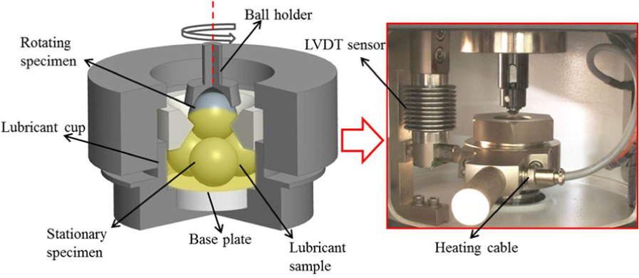
The primary objective of this research work is to develop an innovative novel experimental setup, namely, EHVSL assisted machining technique to improve performance of machining process with an aim to eliminate the usage of environmental effective cutting fluid in machining operation. High transfer rate of coolants with sufficient amount of lubricant thin film at tool–chip and tool–work interface is very important to achieve better process performance in terms of improving product quality and tool life. 30 The goal of this investigation is to design and develop an EHVSL experimental setup (shown in Figure 1). It is a new technique introduced in the manufacturing process to improve process performance in turning operation. The developed experimental setup comprises high-voltage (HV) generator, air compressor, syringe pump and electrostatic spray nozzle. The detailed explanation about EHVSL supply system, nozzle design and electrostatic charge properties is given in the forthcoming section.
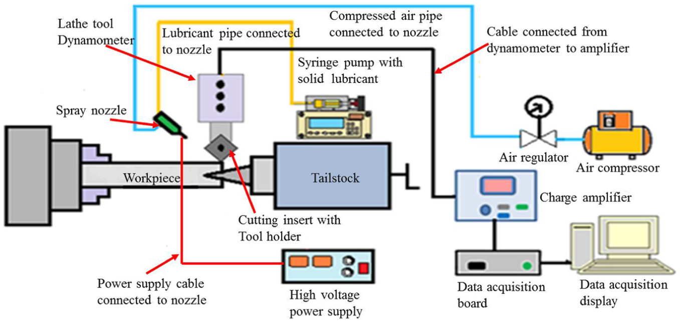
Schematic diagram of developed electrostatic high-velocity solid lubricant–assisted machining experimental setup.
EHVSL setup
The EHVSL system consists of a syringe pump, HV power supply, spray nozzle and air compressor as shown in Figure 1. To create a required electrostatic force within the sprayed solid lubricant particles, an HV (negative) potential of 0–10 kV was employed and connected by the cable to the tip of the nozzle. The system uses contact electrification to charge the lubricant particles in the nozzle and an electric field to aid uniformly charged lubrication at chip–tool and work–tool interface surfaces. The system makes use of electrostatic charging principle to charge the suspension of solid lubricants passing through the specially designed nozzle as shown in Figure 2. The lubricant delivery system is developed to supply minimum quantity of solid lubricant suspension to the tool cutting edge surface, to provide good lubrication during machining. As soon as the liquid in the nozzle reaches a critical point, the charged liquid particles, which are still under pressure, are emitted from the nozzle onto the working surface, and the tool gets lubricated.
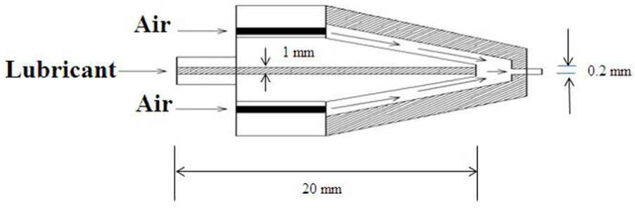
Schematic diagram of nozzle tip.
The function of HV supply (shown in Figure 3) is to create the necessary electrostatic charge within the sprayed lubricating particles to facilitate solid lubricants to stick (adhere lubricants) themselves to the hot machining zone (rake face and flank face). The nozzle was positioned along the tool–chip and tool–work interfaces, to apply solid lubricant suspension effectively to the hot machining zone. The syringe pump is used to maintain steady flow rate of solid lubricants. The electrostatic field created at the nozzle tip obliges to ensure the charging of solid lubricants’ suspension owing to ionized airflow in the stream, and consequently, the in-line air supply through nozzle provides easy transfer of lubricants toward the tool–chip and tool–work interfaces effectively. A photographic view of the developed EHVSL setup is shown in Figure 4. After ensuring the experimental setup for proper performance, the experiments have been performed on Ti–6Al–4V alloy.
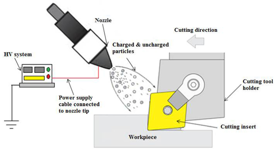
Schematic view of EHVSL with cloud of tiny highly charged solid lubricant particles.
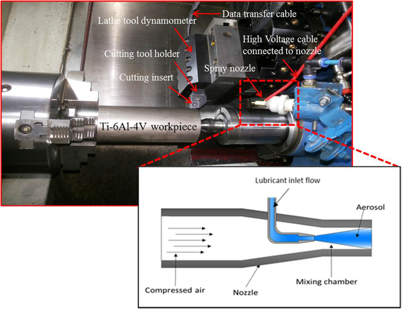
Photographic view of developed electrostatic high-velocity solid lubricant–assisted machining experimental setup.
Nozzle design
The electrostatic spray nozzle is the most significant unit of EHVSL system. Keeping its basic principle in imparting electrostatic charges, the authors of this article built a simple electrostatic spray nozzle based on modularized design with commercially available components and materials and industrial manufacturing standard. The main function of the nozzle is to direct the flow of charged solid lubricant particles as a high-velocity jet at a tremendously minimum flow rate to those localized “hot-zones” (chip–tool and work–tool interfaces) in the cutting area with an MQSL consumption. As shown in Figure 2, the schematic view of EHVSL delivery system was designed and developed for turning operation. For effective lubricant deposition process of charged solid lubricant particles, the nozzle is attached to the cutting tool holder. The nozzle position was adjusted in such a way to supply charged solid lubricant suspension selectively to the tool rake face and flank face of the cutting tool. The tool rake face and flank face are the two important faces of the cutting tool, where most crater wear and flank wear occur, respectively. Improving its efficiency as a coolant, the electrostatic high-velocity thin pulse jet solid lubricant may form a liquid cushion on the tool–chip and tool–work interfaces. Solid lubricants were first charged at the nozzle tip and the charged solid lubricant particles were alienated into droplet particles by the compressed air. The charged solid lubricant particles will quickly penetrate and adhere on the surface of chip–tool and work–tool interface to form thin lubricant film.
Electrostatic charged properties
The function of HV supply is to generate the necessary electrostatic charge within the sprayed lubricant particles and facilitate solid lubricant particles to adhere to the chip–tool and work–tool interface (hot-zones). The strength of the electric field required to transfer the lubricant particles toward the grounded workpiece is evaluated by calculating the mean charge-to-mass ratio (qmax/m) of the lubricant particles. The calculated particle mean charge-to-mass ratio and transfer efficiency of the developed lubricant deposition system are presented in equation (1). The particles pass through a highly charged and ionized electric field at the nozzle tip applying a strong negative charge to each particle.
In electrostatic charging deposition process, the amount of charge acquired by the solid lubricant particles not only determines their trajectories but also their adherence tendency to the metal substrate.31,32 The studies revealed that the particle adherence tendency is a function of the mean surface charge-to-mass ratio (
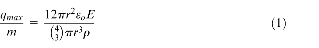
The measurement of this mean surface charge-to-mass ratio is very helpful in electrostatic solid lubricant process as it provides an indication of how well a particular lubricant experimental setup is working, which, in turn, may be used to evaluate the transfer efficiency of the system.
Experimentation procedure
To assess the performance of the developed EHVSL system, turning experiments were carried out with proper selection of concentration and flow rate of solid lubricant suspension in terms of improving machining properties and surface integrity of the machined part and comparing the same with the existing cooling/lubrication methods.
Selection of concentration of solid lubricant suspension
There is general agreement concerning the admirable performance of solid lubricant additives referred to as dry lubricants, but there exist controversies regarding the effectiveness of solid lubricant suspensions’ extant in liquid lubricants. Therefore, efficiency, particle size and precise suspension of the solid lubricant in base oil are of great importance in terms of penetrating lubricants effectively in the machining zone. In this study, 10 µm size MoS2 solid lubricant particles were suspended in base oil. The solid lubricant additives with varying concentrations in the base oil were taken as 0%, 10%, 20%, 30%, 40% and 50% by weight ratio.
In this study, to determine the wear prevention properties of applied solid lubricants, and to compare the characteristics of solid lubricant additives with varying concentrations, wear test (ASTM D4172) experiments were performed on four-ball tester (shown in Figure 5) machine procured from Ducom Instruments (India). MoS2 with an average particle size of 10 µm with varying concentrations were suspended in SAE 40 oil. Test pieces consist of four hard steel balls, 1/2 in (12.7 mm) in diameter, made from AISI 52100 (EN-31). The top ball rotates on a vertical axis, while the three other steel balls are clamped together and covered with a solid lubricant with varying concentrations in base oil. The contact surfaces of the balls are covered with test lubricant (solid lubricants), a constant load of 40 kg f (392 N) is applied and a timed test is performed; the top ball is rotated at 1200 r/min for 60 min. The temperature of the lubricating oil is regulated at 75°C (167°F). To elude the impact of residual lubricant of the previous experiment, the specimen was cleaned with acetone.
A schematic view of four-ball test machine.
Selection of flow rate of solid lubricant in EHVSL condition
It is paramount in the machining process to supply sufficient amount of coolant/lubricant in the hot machining zone (chip–tool and work–tool interfaces). In addition, to reduce the high cutting temperatures and frictional forces, sufficient coolants/lubricants are applied, which leads to increasing the surface quality of the product produced. To evaluate the optimum and required flow rate of solid lubricant in the machining process, turning experiments were carried out on the developed EHVSL setup with varying flow rates (5, 10, 20, 30, 40, 50 mL/h) of solid lubricant with constant machining parameters. To assist solid lubricants effectively in the machining zone, a constant and continuous air pressure of 5 bar is used. A standoff distance of 20 mm was maintained from nozzle tip to work–tool interface zone throughout the experiments.
Selection of design of experiments
In this work, the experiments were designed using Taguchi’s design of experiments, L27 orthogonal array. To study the performance effect of different machining parameters in the presence of an electrostatic high-velocity solid lubricant, MQSL, MQL and flood coolant and dry conditions, different sets of experiments were performed.
Experimental tests
To assess the performance of the developed EHVSL setup, the experiments were performed on HMT PVT 260 high-power rigid computer numerical control (CNC) lathe machine. The machining tests were performed under dry, wet, MQL, MQSL and EHVSL assisted machining conditions. Water-soluble cutting oil was used in the conventional cooling condition. In case of MQL, compressed air with a minimum quantity of water-soluble cutting oil was used and applied at a flow rate 300 mL/h. In case of MQSL assisted machining, 20 wt% MoS2 solid lubricant particles (10 µm) were selected as an additive in SAE 40 oil. The EHVSL deposition process was carried out with a compressed air pressure of 5 bar and a voltage potential of 7 kV. At the end of the nozzle tip, the droplets of charged solid lubricant particles were temporarily adhered to the chip–tool and work–tool surfaces of the substrates as a result of the electrostatic forces.
In this investigation, Ti–6Al–4V grade 5 alloy bar is used for the machining process. The reason for increasing popularity of this grade of titanium alloy lies in the fact that it combines the characteristics of good corrosion and wear resistance. The variable factors evaluated during the experiments in this work were cutting speed, feed and depth of cut. The details of experimentation have been shown in Table 1.
Experimental condition.
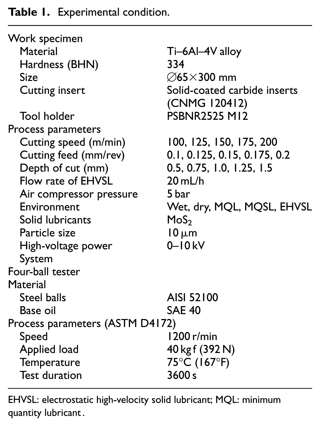
EHVSL: electrostatic high-velocity solid lubricant; MQL: minimum quantity lubricant.
Results and discussion
During turning of titanium alloy, excess heat is generated at the (1) primary heat source from a shearing zone, because plastic deformation takes place; (2) secondary heat source from a shearing zone along tool–chip interface and (3) third source from rubbing zone along tool–workpiece interface. The performance of turning Ti–6Al–4V alloy under the developed EHVSL setup is compared with the existing cooling techniques and has been assessed in terms of surface roughness, cutting force and tool wear.
Selection of MQSL
To investigate solid lubricant concentration, wear prevention tests were performed on four-ball tester. The variation in cutting force with respect to the various flow rates of solid lubricants was studied. This study helps to estimate the optimum concentration suspension of solid lubricants in base oil and flow rate of solid lubricants during the machining process.
Analysis of solid lubricant concentration
The aim of this work is to understand the better role of base lubricant and additives in the boundary regime. Figure 6 shows the variation of friction coefficient and WSD (Wear Scar Diameter) at varying additive concentrations of MoS2 solid lubricant. From Figure 6, it was observed that the coefficient of friction decreases with an increase in MoS2 contaminants. The results revealed that for 0 wt% additive contaminated lubricant exhibited higher friction coefficient than that of other contaminants. The second increase in friction coefficient was found for 10 wt% MoS2 suspended lubricant oil. Among the considered conditions, solid lubricant with 20 wt% provides better performance in terms of reducing friction coefficient and WSD. The change in friction coefficient for other concentrations was found with negligible changes. The results revealed that suspension of higher concentration of MoS2 solid lubricant in base oil is effective in reducing friction coefficient. When pure lube oil was contaminated with 20 wt% MoS2, the friction coefficient decreased. It can be observed in Figure 6 that the increase in additive concentration in base oil yields better friction-reduction behavior. One of the reasons might be the effect of viscosity. 18 This can be attributed to the fact that a certain amount of applied solid lubricants was accumulated on the surface of friction pairs, which is advantageous for the lubricant to form sufficient lubricant film to provide effective lubrication.
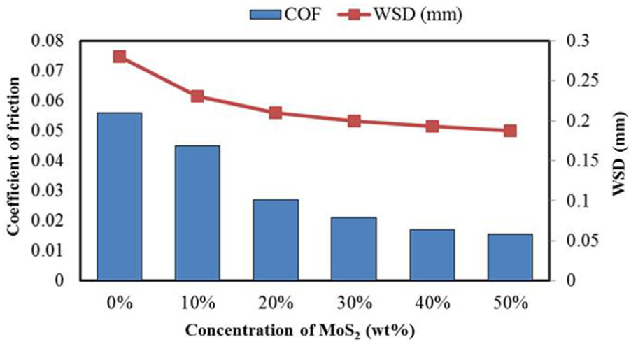
Friction coefficient and WSD for various concentrations of solid lubricant.
The micrographs of the worn surfaces of the stationary ball specimen for varying suspensions of MoS2 concentration are shown in Figure 7. It can be seen from Figure 7 that adhesive wear occurred on the ball surfaces in all considered conditions. The significant improvement in WSD was observed for 20 wt% as compared to other concentrations. This is because the increase in the suspension of additive in base oil leads to greater binding of the lubricants, which in turn provides an excellent resistance to shear force. 28 Although an increase in concentration more than 20 wt% in the base oil has shown negligible changes on WSD.
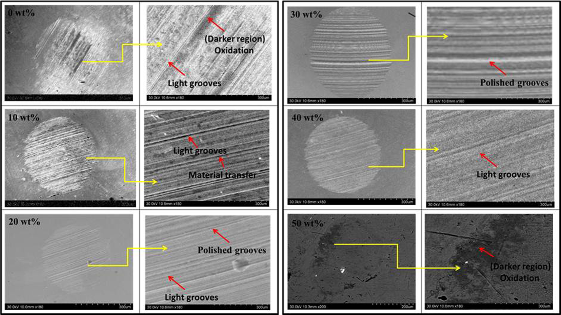
Microscopic images of worn surface of stationary steel balls at various concentrations.
Analysis of flow rate of solid lubricant
To investigate the optimum and required quantity of lubricants in the interface zone, a series of turning tests were performed on Ti–6Al–4V alloy at 100 m/min machining speed, 0.1 mm/rev feed and 0.5 mm depth of cut. To supply solid lubricants with a constant flow rate, syringe pump is used. Figure 8 shows the cutting force with varying flow rates of solid lubricant. MoS2 (10 µm) with 20% concentration of weight ratio in base oil was taken as the lubricant.
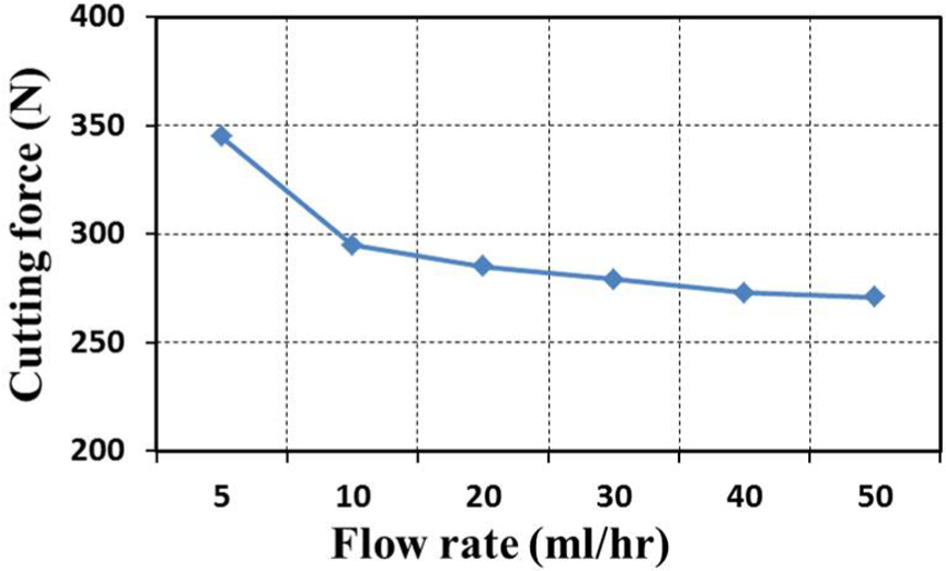
Variation in cutting force with varying solid lubricant flow rates.
From Figure 8, it was observed that as the flow rate of lubricant increases from 5 to 20 mL/h, the cutting force decreases, although not much difference was observed beyond 20 mL/h. The layered solid lubricant particles shear easily under traction to yield low friction. During the application of the lubricant (5 mL/h) in the machining zone, it was observed that the lubricant is not adhered effectively, as the workpiece rotates, the applied lubricants on tool-chip interface slips away. It has been clearly observed that with the increase in the flow rate of lubricants, the size of droplets increases. For an efficient lubrication system, it is always recommended that there should be more number of lubricant droplets with less particle size so that the lubricants can cover maximum surface area. 26 Hence, from the obtained results it was observed that MoS2 solid lubricant with 20 wt% in base oil at 20 mL/h flow rate was able to generate mist with good quality of lubricant. It was also observed that when high flow rate of lubricant was applied in the machining zone, the lubricant applied on the tool–work interface zone splashes (put away lubricant from work–tool interface zone). Hence, from the obtained results it can be concluded that 20 mL/h is the best flow rate for MoS2 assisted machining of Ti–6Al–4V alloy.
Effect of EHVSL on surface roughness
Surface roughness (Ra) is one of the most important factors in the machining process as it significantly impacts the friction coefficient, fatigue strength, wear rate, lubrication and corrosion resistance of the machined surface. 33 The “Ra” parameter was measured in three different positions on Ti–6Al–4V alloy bar of 65-mm-diameter machined surface under different environmental cutting conditions considered in this research work. Surface roughness was analyzed at various machining conditions and further compared with dry, wet, MQL, MQSL and EHVSL conditions as represented in Figure 9. From Figure 9, it was observed that in all the considered environments, at high cutting speed conditions better surface finish was observed on the workpiece owing to lower cutting force generated. It was also observed that at high material removal rate condition (feed and depth of cut), surface finish increases. This is estimated because as the feed and depth of cut increase, more material should be removed from the workpiece, as significantly more energy is required. 19 In addition, at higher cutting speed, the built-up edge (BUE) on cutting tool surface turns out to be less, chip breakage decreases and hence the quality of the machined workpiece surface is achieved. This is expected because higher cutting speeds induce quite easier chip removal from the workpiece resulting in a better surface roughness.
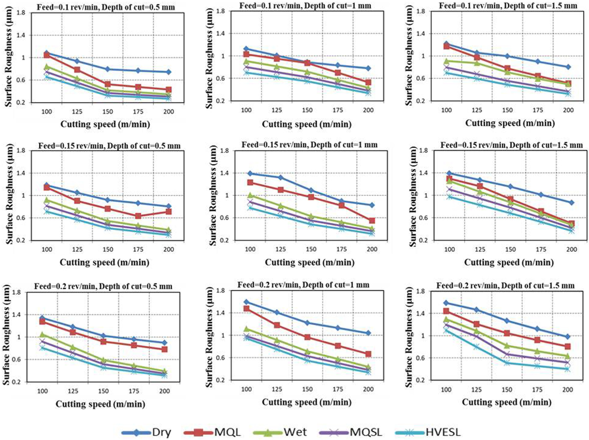
Surface roughness at cutting speed = 100, 150, 200 m/min, feed = 0.1, 0.15, 0.2 mm/rev and depth of cut = 0.5, 1, 1.5 mm under different environmental conditions.
Furthermore, the results show that during EHVSL lubrication condition (shown in Figure 9), surface roughness significantly improved by 11% when compared with MQSL-assisted machining condition. It also leads to an average surface roughness of 25%, 40% and 57% during EHVSL-assisted machining conditions compared to wet, MQL and dry cutting conditions, respectively. During EHVSL machining process, charged spray solid lubricant droplet particles penetrate effectively at chip–tool interface zone and form a thin lubricant film and adhere to the contact area leading to improved friction at the work-tool contact surface. The lower values of the surface roughness obtained during EHVSL machining process can be attributed to the MoS2 inherent lubricating properties and thereby reduce the cutting temperatures generated and further prevent the tool wear and contributes to improve surface quality. However, it is evident that lubricants with high-viscosity, high-velocity thin pulse jet system substantially improve the surface roughness mainly through controlling the deterioration of the auxiliary cutting edge by abrasion, chipping and BUE formation.
The high roughness values were observed during dry machining condition. During MQL process, it was observed that heat removal is predominantly high in the evaporative mode, which is more capable than the convective heat transfer prevalent in conventional wet turning. 5 It was found that during EHVSL process, the solid lubricants supplied effectively to the rake face and flank face and firmly stick to the workpiece causing the promotion of plastic flow on the back side of the chip due to Rebinder effect. 13 Close observation of crystal-lattice conceals that due to the presence of free electrons in MoS2 particles, the adhesion tendency is more to metal surfaces, resulting in low friction forces as compared to MQSL machining process. This was expected since sufficient lubricant with high pressure was employed for proper lubrication in machining zone. In fact, reducing the interface temperature by cooling action and friction by lubrication action eventually results in improving the surface roughness. 34
Suresh Kumar Reddy and Venkateswara Rao 13 reported that minimizing the cutting force and specific energy results in an increase in the surface quality and tool performance. Suresh Kumar Reddy and Venkateswara Rao 35 also studied that during the machining of medium carbon steel, an average surface roughness reduction of 23% was observed with MoS2 solid lubricant when compared with wet cutting fluid and 43% reduction of surface roughness was observed in comparison to dry machining. Reddy and Yang 36 report that surface roughness decreases due to lubricating action of solid lubricant at high temperatures. It was observed that the overall performance of application of solid lubricant was found to be superior to that of dry, wet and MQL in terms of improving high heat generation, which minimizes deterioration of the cutting edge by chipping, BUE formation and abrasion.
Effect of EHVSL on cutting force
The machining force components play a more significant role in evaluation of the performance of machining process. Several factors such as workpiece, cutting insert, tool geometry and the presence of lubricant have a considerable effect on machining force, which governs the power requirement in the machining process. During the machining process, the behavior of average machining force components under considered environmental conditions is shown in Figure 10. It was observed that cutting speed was found to have a significant effect on cutting force. Figure 10 shows that at high-speed cutting conditions, cutting force decreases and that reduces the shear strength of the material at the machining zone. Due to the formation of thin solid lubricant film in the machining zone, good friction and wear reduction performances are observed and machining becomes easier. 28 The solid additive particles of the layered solid lubricants shear easily under traction to yield low coefficient of friction.
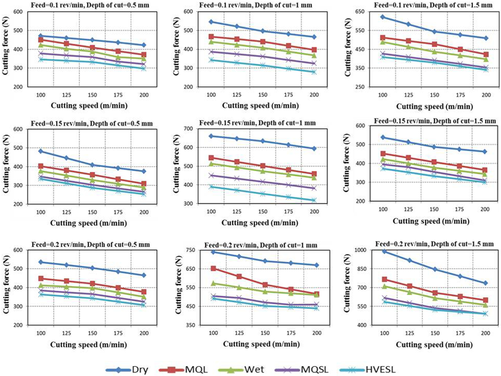
Cutting force at cutting speed = 100, 150, 200 m/min, feed = 0.1, 0.15, 0.2 mm/rev and depth of cut = 0.5, 1, 1.5 mm under different environmental conditions.
Upon further increase in machining speed, the friction coefficients at the tool–chip interface on the rake face of the cutting tool result in a decreased shear plane angle. 6 Therefore, the cutting force decreases at high-speed condition. As a result, the cutting speed is found to be a more significant effect in terms of inducing the machining force. The results also showed that with an increase in feed and depth of cut in the cutting process, machining force increases. This can be attributed to the ability that with an increase in feed and depth of cut, the rate of plastic deformation in the primary shearing zone increases. 23
Considerable reduction in cutting force was observed during EHVSL and MQSL machining condition as compared with dry, wet and MQL machining conditions. From the obtained results, it was observed that dry machining is associated with enhanced friction, which leads to increased cutting temperatures, thus increasing the cutting force. This could be due to the absence of coolant in the hot interface zone. Thus, the negligible amount of solid lubricants that can still reach the tool–chip interference zone seems to have a vital effect on reducing high temperature. Whereas during MQL process it was observed that the lubricant cannot penetrate effectively into the tool–chip interface. The EHVSL lubricants act predominantly and contribute to reduce the friction and the chip-tool–workpiece contact areas, allowing higher cutting speeds, better surface roughness and greater tool lives. Compared to wet, dry, MQL and MQSL machining conditions, the efficiency of the lubricant in reducing the friction at the tool–workpiece–chip contact zone is evident by a reduction of cutting force under EHVSL machining condition. Further, results revealed from the tested experiments that the cutting force reduced by 7%, 17%, 23% and 31% less cutting force were occurred during EHVSL cutting condition as compared with MQSL, wet, MQL and dry cutting conditions.
The machining performance of EHVSL system provides considerable improvement than MQSL system mainly due to better penetration of solid lubricant into the machining surface which provides higher lubricity characteristics between the chip–tool interface zone. Hence, from the obtained results, it can be extracted that EHVSL system improves the surface quality of the machined surface and tool life by reducing the machining force. This further leads to improvement in productivity. The significant reduction in cutting force strengthens the use of EHVSL system in manufacturing industries as the best alternative solution for effective reduction in frictional forces between work–tool interface.
Molybdenum disulfide is used as coolants and is recognized to be good solid lubricant because of significant reduction in heat generated between sliding components, which could have contributed to the reduction in cutting forces.20,28 From the previous studies, it was observed that molybdenum disulfide (lamellar material) generally has good load carrying capacity with a corresponding low friction coefficient under sliding condition.19,32 The considerable reduction in machining forces by applying MoS2 and graphite machining process can be attributed to the formation of thin lubricant film, thus reducing the material’s shear strength in the interface zone and hence making the machining easier. 25 Ricardo et al. 29 observed that due to the lubrication action of solid lubricants in hot cutting zone, the temperature developed between the high-temperature zone decreases, minimizing the shear strength of the material. Hence, reducing the frictional force and eventually improving tool life, resulting in good surface quality of the products. Significant reduction in cutting force by EHVSL technique is attributed to the development of a thin lubricant film, reducing the friction coefficient at chip–tool interface zone, so that machining becomes easier.
Effect of EHVSL on tool wear
Tool flank wear plays an imperative factor in prompting the tool life and productivity of the machined surface. An increase in temperature at the machining zone strongly impairs the physical properties of the cutting tool material and thus reduces the particle penetration withstand ability which further leads to influence the performance of the cutting tool.21,37 Tool wear studies were performed to estimate the performance of EHVSL in machining Ti–6Al–4V alloy at varying machining conditions. Figure 11 shows the flank wear at different environmental conditions. It was observed that the flank wear in all the considered environment conditions was increased steadily with an increase in cutting speed. It was also observed that tool flank wear increases with an increase in feed and depth of cut. This could be due to an increase in cutting temperature in the machining zone, increase in plastic deformation rate and reduction in the strength of the tool. 12
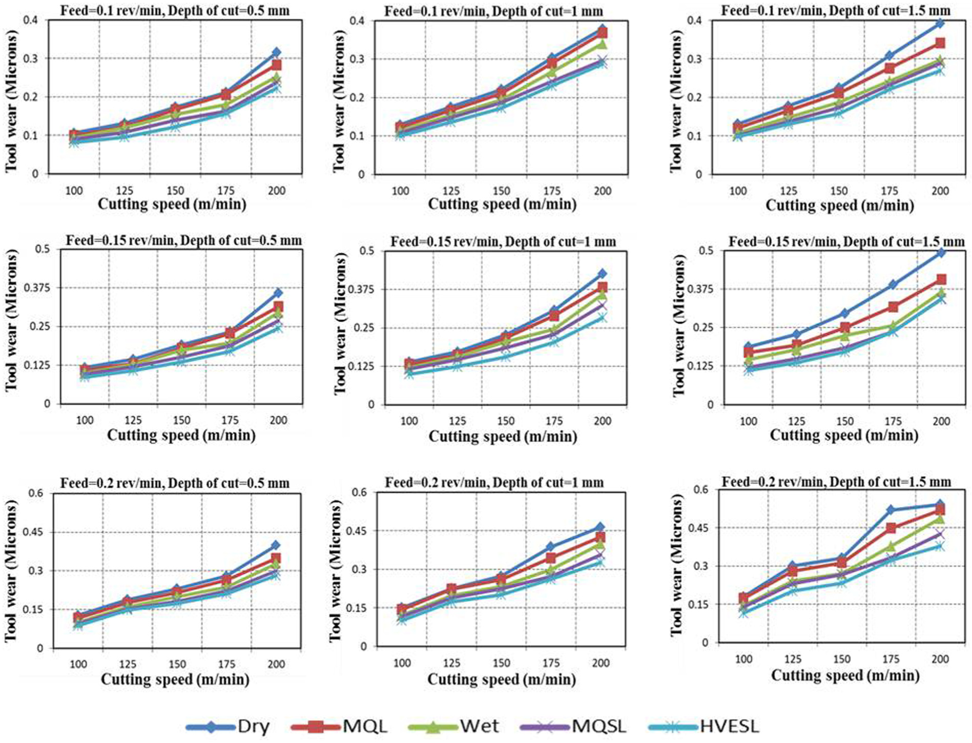
Tool wear at cutting speed = 100, 150, 200 m/min, feed = 0.1, 0.15, 0.2 mm/rev and depth of cut = 0.5, 1, 1.5 mm under different environmental conditions.
Furthermore, during EHVSL condition, flank wear performed abundant ability in maintaining the wear resistance. However, when comparing the conditions of lubrications used, application of MoS2 solid lubricant with EHVSL supply system showed a significant improvement compared to MQSL, MQL and wet and dry cutting conditions. The results revealed that MoS2 with developed EHVSL setup leads to the reduction in tool flank wear by 9%, 12%, 18% and 23% compared to that of MQSL, wet, MQL and dry machining conditions. This could be due to reduced cutting forces and temperatures. This observation implies that MoS2 solid lubricant can work effectively as a coolant on cutting tools. Furthermore, the use of MQSL assisted machining showed a very less significant difference when compared with the EHVSL condition. It has been observed that during EHVSL condition, the solid lubricant (MoS2) melts and smears, forming a thin layer of lubricant between the tool–chip and the tool–work interfaces. This is probably due to good adhesion of solid lubricants near the cutting zone with minimum plastic deformation by offering low friction coefficient and minimum shear resistance.
HPC systems were applied to the tool–chip interface to adequately penetrate and change the thermal, mechanical and frictional conditions in the machining zone. 14 Examinations of the wear surfaces revealed that in all the testing environments, the presence of BUE at the cutting edge tool could be due to the adhesion of machined work material on the cutting tool surface. Adhesion of the workpiece material on the tool flank face of the cutting tool was observed under high cutting parameter conditions. 32 The flank wear of the cutting tool has been analyzed using scanning electron microscope (SEM). Figure 12 shows details of the SEM analysis. In view of observation of great amount of adherent work materials on the tool surface, they were embedded in hydrochloric acid (HCL) for 48 h to remove them and allow clear observation of worn areas.
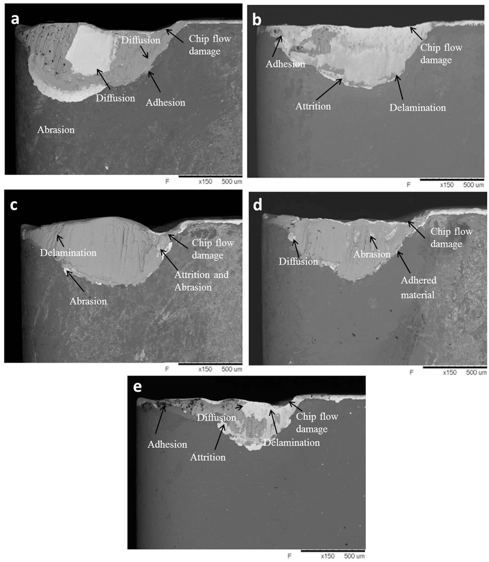
SEM images of cutting tool at cutting speed of 100 m/min: (a) dry, (b) MQL, (c) wet, (d) MQSL and (e) EHVSL.
Figure 12 shows details of the worn areas of the tools used with EHVSL, MQSL, wet, MQL and dry cutting conditions. From the study done by Trent and Wright, 38 the wear mechanisms involved can be linked to the details of the worn areas of the tools. The smooth worn areas seen on the tool surfaces indicate the occurrence of chemical wear at atomic levels (diffusion). Attrition and abrasion depend more on the active lubricant area. 39
Whereas in the rougher portions of the worn area due to attrition mechanism particles of the tool were plucked off. By observing parallel ridges, abrasion as a typical wear mechanism can be characterized on the tool surface. Also, chipping and spalling were observed. Because of the high-temperature dependency of diffusion in comparison to attrition and abrasion, it can be concluded that cooling action is more important during machining of hard-to-machine material. The active lubricant area is the major factor on which attrition and abrasion depend. The superior performance of EHVSL is because of the combination of both the actions. From Figure 12(e), the observed presence of adhered MoS2 on the tool surface shows clearly that the lubricant action is working.
Conclusion
This research work influences the novel methodology in developing EHVSL assisted machining process to apply lubricants effectively to the machining zone with a goal to improve the performance of machining process during turning Ti–6Al–4V alloy. An outstanding outcome of this research work is that the solid lubricants with low particle size with constant flow rate using electrostatic technique provide better performance comparing to the existing machining techniques. The promising results obtained in this work highlight the following important conclusions:
With the developed experimental setup, the concept of minimizing or eliminating the use of cutting fluids in hard turning of Ti–6Al–4V has been successful with the application of MoS2 as solid lubricant.
The force component was drastically reduced in the domain of the tested conditions. This substantial reduction can be attributed to the lattice layer structure of solid lubricants, which act as an effective lubricating film.
To supply lubricants effectively and to considerably improve the machining performance, EHVSL system is an effective and alternative technique compared to MQSL, MQL, flood cooling and dry machining processes.
The EHVSL technique has proved to be a versatile technique in terms of improving eco-friendly machining processes by lowering part cost and quantity of lubricant. Product quality improvement has been achieved due to effective penetration of lubricant into the rake face and flank face of the cutting tool.
The overall machining performance during EHVSL technique is found to be superior to that of MQSL, MQL, wet and dry turning by considering surface roughness, cutting force and tool wear as performance indices.
The results obtained highlighted that it is essential to apply lubricants selectively to the machining zone with considered environmental requirements toward finding out an improved method for specific hard turning of Ti–6Al–4V alloy. The carried research work clearly demonstrates the cost-effectiveness by abandonment of the cutting fluid and also at the same time improving economic, environmental and social performance with solid lubricants in the context of increasing industrialization.
Footnotes
Declaration of conflicting interests
The author(s) declared no potential conflicts of interest with respect to the research, authorship and/or publication of this article.
Funding
The author(s) disclosed receipt of the following financial support for the research, authorship, and/or publication of this article: The complete research work was carried out under the financial support of the Department of Science and Technology (DST), India, through sponsored project—SR/S3/MERC/031/2012.