
Abstract
In contrast to most other manufacturing technologies, in electrochemical machining processes only slight changes in material characteristics in the rim zone of workpieces are stated in the literature. Due to the physical active principle, no thermo-mechanically induced phase changes or the evolution of a so-called white layer were ever observed. Aside of this fact, a not inconsiderable number of smaller modifications in the rim zone were found in the past. The most common effects occurring during electrochemical machining are the generation of a passive layer on the surface by changing the local chemical composition of the material, the selective dissolution of one metallic phase, or the occurrence of flow marks. Consequently, the last two effects also change the surface roughness as the marks and dissolved phases represent ditches in the surface. Therefore, in this article, material modifications occurring during electrochemical machining are presented. Their influence on the surface integrity is exemplarily analyzed for the heat-treatable steel 42CrMo4. In addition, first steps for a correlation of material loadings that promote these changes, the so-called process signature, are made. Based on this, the influence of different machining parameters can be compared to set up rim zone properties purposefully.
Introduction
Components functionality strongly depends on characteristics of the rim zone, which differ from those of the bulk material. Nevertheless, these characteristics can hardly be set up by manufacturing processes reproducible in advance. 1 Electrochemical machining (ECM) has the unique feature that the rim zone is not affected thermally and is almost free of mechanical damage in combination with high dissolution rates and best surface roughness. Besides this, there are several modifications evolving during this machining process. Therefore, it is necessary to analyze the origin and causes of these modifications to set up a comprehensive process signature for manufacturing processes with chemical active working principle. This signature allows the defined set up of rim zone properties in advance and thus ensuring components functionality during its life time. For this reason, the most important modifications and their influence are examined in this article both theoretically and experimentally.
Material modifications
Surfaces and their properties are mostly set up by the last manufacturing step in a process chain and have to ensure the functionality during components life cycle. These machining-induced changes of material properties are called material modifications. Due to the considerable number of rim zone properties, there is an even higher number of modifications in the rim zone being responsible for these properties. However, different manufacturing processes produce these modifications in different ways corresponding to their main active working principle. The energy-based correlation between modifications and loadings is called process signature. 1 ECM produces a variety of smaller modifications that can hardly be achieved by other manufacturing technologies. For this reason, the main modifications developing in ECM processes, namely flow grooves, oxidation layer, pitting corrosion, and selective dissolution, are presented and analyzed as an overview subsequently.
Beside the material loadings, the material modifications in ECM are also influenced by the initial state of the material. 2 Therefore, for comparability, the material used for the examination in this article is always 42CrMo4 steel, with a previous normalizing heat treatment. Therefore, all specimens were heated up to 850 °C with 10 K/min; afterward, the specimens were kept for 120 min at this temperature. Finally, they are cooled down in the heat treatment furnace by 1.7 K/min.
For the comparability, all electrochemical experiments were performed with the same electrolyte boundary conditions. The temperature was set to 36 °C as this is a typical temperature from industrial application. For an equal electrical conductivity, the salt content was 20 wt % for sodium nitrate and 12 wt % for sodium chloride. With this, the electrolyte conductivity was set to 160 mS/cm.
Flow grooves
Generally, flow grooves or flow marks are an undesirable effect occurring during bad or inhomogeneous electrolyte flushing conditions. These grooves, developing in regions of high flow velocities, have the appearance of stream lines. Indeed, in one examination, it was shown that the flow has interacted with chemical material removal changing locally the chemical dissolution behavior. 3 Another examination leads this effect back to small inclusions in the workpiece bulk material. 4 From the practical application, it is known that the depth of this effect and thus the damaged zone varies in the range of a few to tenth of microns. Nevertheless, the material stresses and mechanisms causing these modifications are not closely studied in the literature. For this reason, a first analysis is made here. The influence of fluid velocity on the quantity and manifestation of flow grooves is examined first by different ratios of pressure at the inlet and outlet and thus different flow velocities at constant gap width (Figure 1). Therefore, circular specimens with a diameter of 24 mm were manufactured. Beyond the inlet, there is an expanding area causing a slowdown of the electrolyte flow. The second half of the specimen forms a nozzle causing an acceleration of the electrolyte where the flow grooves occur. For statistical certainty, each experiment is performed three times.
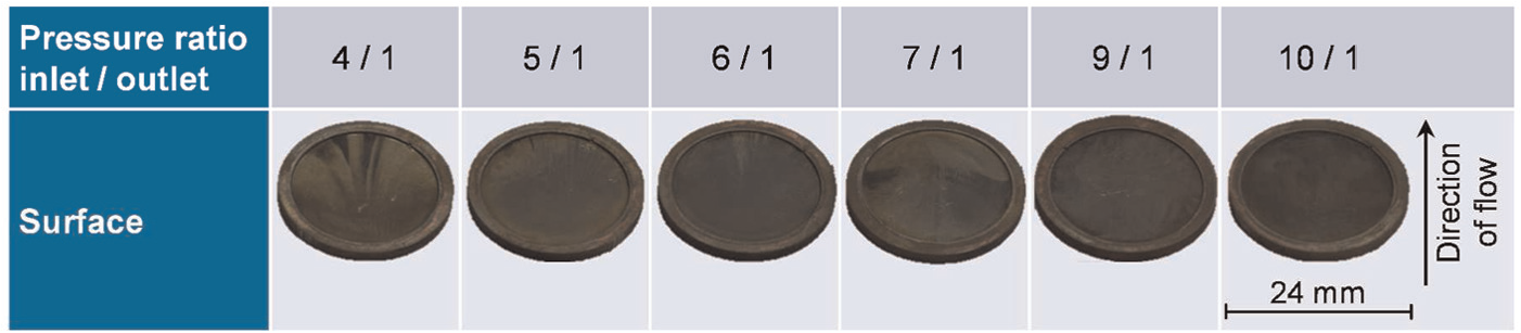
Influence of pressure ratio and induced flow velocity on appearance of flow grooves in 42CrMo4.
The analysis of the specimens shows that there is no general dependency between occurrence of flow marks and the pressure ratio–induced average flow velocity. As the flow velocity cannot be determined directly from experiment, additionally the flow field was analyzed with a numerical model of the ECM process developed at WZL.5,6 The model showed that the average flow velocity and the maximum flow velocity increase with increasing pressure ratio. Maximum flow velocity at the pressure ratio of 10/1 is around 30 m/s, which is in good accordance with former examinations. 3
Nevertheless, for higher ratios of pressure, the surface quality increases. Due to this, there must be an interaction between fluid flow and chemical reaction like it was assumed by McGeough. 3 Thus, the most probable conclusion is the locally abrasive removal of the passive layer through the electrolyte boundary layer, whereby the electrochemical dissolution is increased (Figure 2). At higher flow velocities, this abrasive removal is more homogeneous and the quantity of flow grooves decreases.
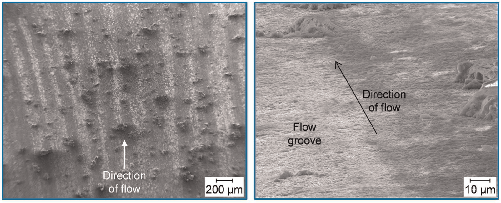
SEM picture of flow grooves in a 42CrMo4 specimen machined in a 20 wt % NaNO3 electrolyte at 36 °C (SE picture, performed on Jeol JSM-7000F at 10 kV left and 15 kV right).
The scanning electron microscopy (SEM) picture shows that the surface within the valleys is very irregular and not smooth (Figure 2, left). However, there are a lot of particles on the surface, but no systematic triggering of flow grooves is recognizable. This is also on account with the fact that these grooves occur localized and not probabilistic distributed over the surface. In addition, the differences in height between surfaces and valleys are very small (right figure), but still also detectable by tactile surface roughness measurements. Nevertheless, it cannot be concluded that this variation of height does not increase depending on the further material removal process.
Considering the interaction between fluid and chemistry, a closer examination of the fluid flow is necessary. The most obvious cause for the abrasive removal of passive layer could be particles in the flow or the wall shear stress due to electrolyte flow changing the surface mechanically. Due to this, the wall surface stress τw of the electrolyte flow is analyzed 7
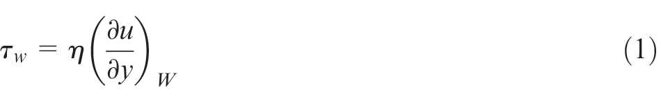
In Newtonian fluids, the surface shear stress is proportional to product of the local change of velocity perpendicular to the surface and the dynamic viscosity η. The velocity of the electrolyte changes within the boundary layer from zero at the workpiece surface to the velocity of the outer electrolyte flow uouter. For this, the wall surface stress can be estimated for the electrolyte with a viscosity ρ at a flat plate with the local Reynolds number Rex to 7
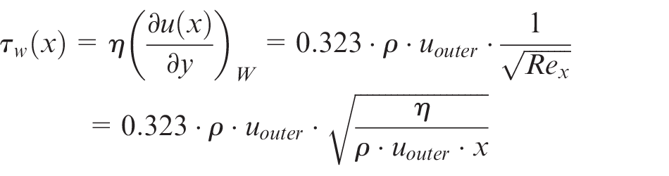
Obviously, for a constant flow velocity uouter in the outer flow, the wall shear stress decreases with increasing flow path x. However, for an increasing viscosity η(x) along the flow path caused by the electrochemical dissolved material and corresponding to the geometric circumstances for changes of the outer flow velocity uouter (x), the wall shear stress can differ strongly. 8 Therefore, the state of fluid flow within the machining gap is additionally examined for different increases of the viscosity ηo/ηi along the flow path with a well-established multiphysical model for sinking ECM processes.5,6 In this case, ηi is the nearly constant viscosity of the pure electrolyte and ηo the varying viscosity at the outlet due to dissolved material (Figure 3).
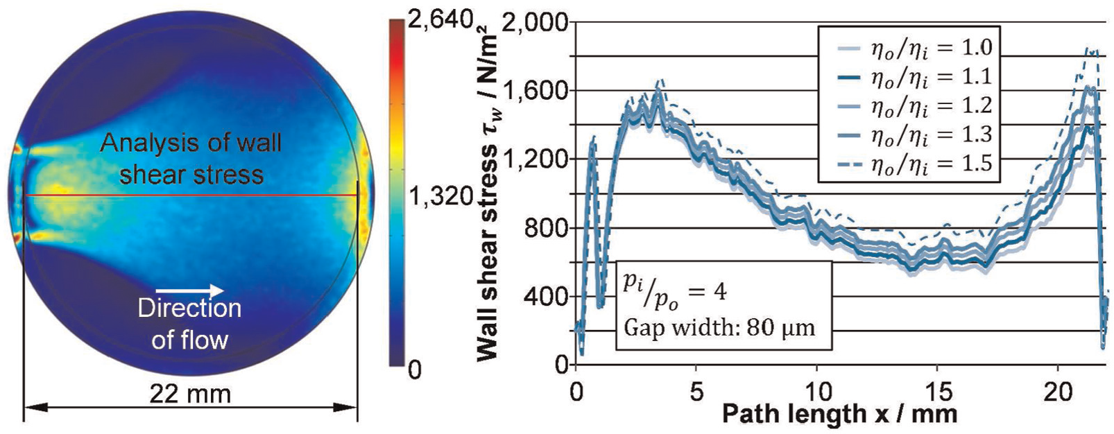
Theoretical wall shear stress development for circular specimen.
According to equation (2), the wall shear stress decreases in the expanding area and increases again in the nozzle area. Due to the dependence of viscosity and flow path, the shear stresses diverge along the flow path (Figure 3, right figure). Still, the overall wall shear stress is far too low for changing the surface contour of the bulk material mechanically. For this reason, there must be more examinations regarding the bonding energy of oxide layer and metal surface including molecular forces as well as the local shear stress of the vicious diffusion layer in the future.
Oxidation layer
The material removal process of ECM is based on the transpassive anodic electrochemical dissolution. One major prerequisite for this is the existence of a passive layer on the anodic workpiece surface. This layer occurs at low electric potentials and thus is fully developed before the transpassive electrochemical dissolution starts. The thickness of the layer varies in a range from a few nanometers to several micrometers depending on the conditions of electrolysis. 9 As the whole electrically exposed surface is covered with this layer of metal oxides, most of the electrical properties of the rim zone are changed. In extreme cases, for example, machining titanium alloys in sodium nitrate electrolyte, the layer is thick and stable in such a manner that the workpiece gets electrically isolated, preventing further ECM. In almost all other cases, the layer shows properties of semiconductors.10,11 For pure iron, there have been several examinations concerning the composition of this layer. In a first approach, the steel 42CrMo4 in a ferrite-perlite state shall be handled like pure ferritic iron, going in account with the high amount of iron (Table 1) and only little amount of minority species.
Chemical composition of 42CrMo4.
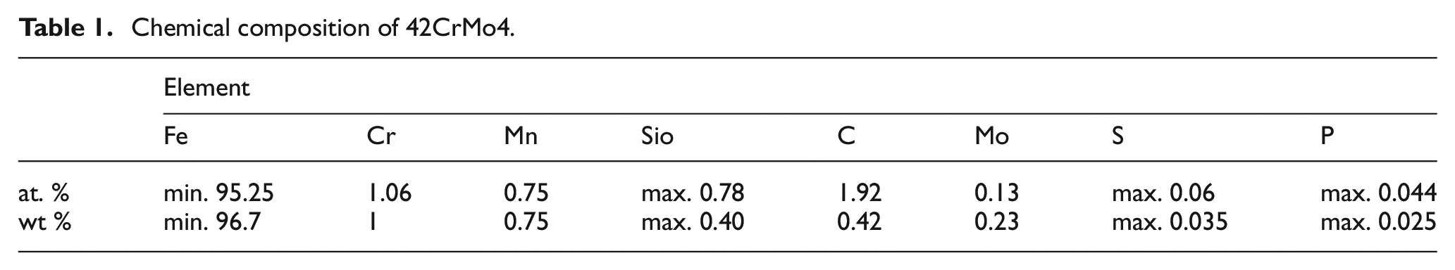
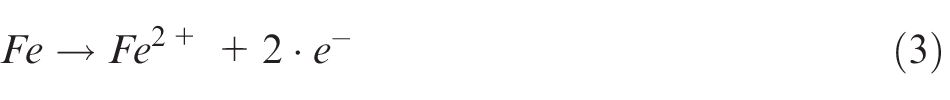
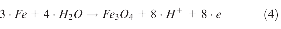
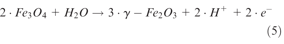
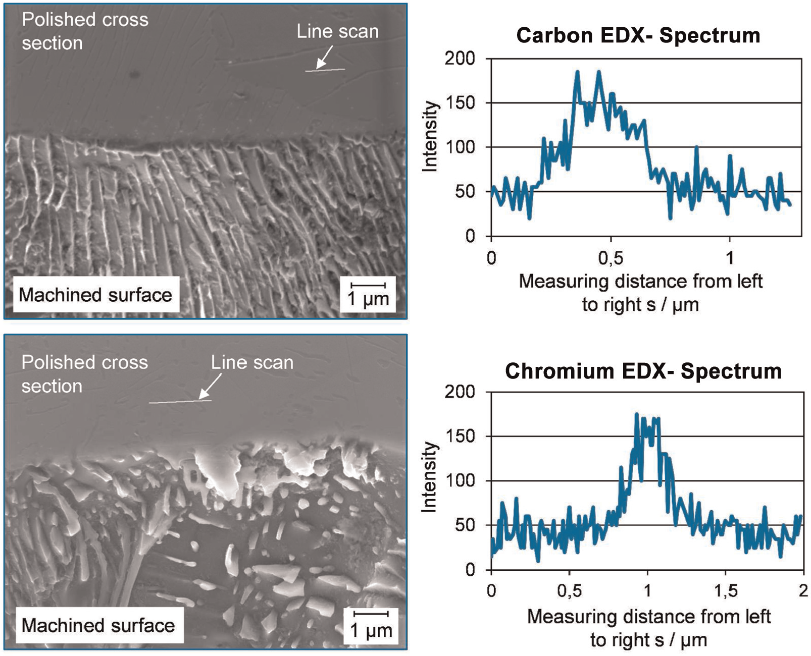
Due to this small part of other alloy components, it is not expectable that there are significant deviations compared to pure iron. 12 In most cases, the oxidation layer is divided into two parts: the inner layer on the metal surface is Fe3O4 and the outer layer exposed to electrolyte is γ-Fe2O313,14 (Figure 4, left). These layers start to develop during the active dissolution of the metal, so that the chemical reaction set up as follows 15
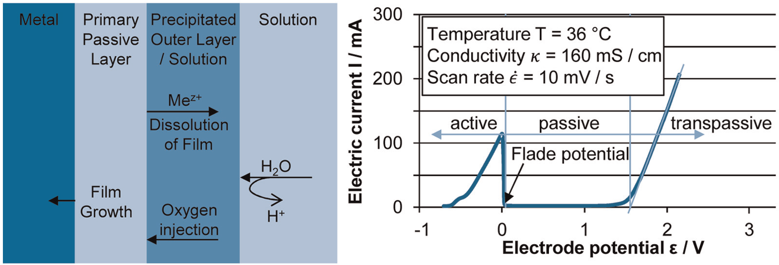
Left: sketch of passive layer according to Macdonald; 16 right: potential current curve of 42CrMo4 in sodium nitrate electrolyte (potential vs saturated calomel electrode).
The completion of coverage by oxides terminates the active anodic dissolution of the metal (3) and it is quantifiable by the Flade potential. 8 Therefore, it can be deducted that the passive layer especially changes the corrosive properties of the material (Figure 4).
To examine these influences on corrosion behavior, two series of specimen out of 42CrMo4 were manufactured with same geometrical dimensions. Both series were sandblasted and the second series was additionally passivated by an ECM step. In the experimental setup, the specimens were exposed to different electrolyte systems. A specimen from each type, passivated and sandblasted, is put either into electrolyte of aqueous sodium nitrate (NaNO3) or sodium chloride (NaCl), both with a concentration of 20 wt % electrolyte salt. Exposing time was constant and difference of material weight was measured. This setup allows a first estimation of the influence of passive layer on corrosion protection. It is expectable that the specimens which were passivated have a lower average weight loss, as oxide layers are used as corrosion protection in industrial application. 17
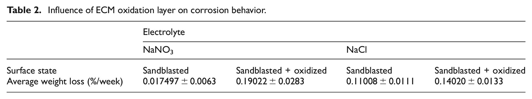
According to Table 2, the average weight loss is higher for passivated specimen independent of the electrolyte system. The overall weight loss is quite higher in sodium nitrate electrolytes. Thus, there seems to be a breakdown of the passive film which can occur under certain circumstances. 18 There are two probable mechanisms causing this behavior, corrosion on one hand and additionally reduction of the oxide layer on the other hand. Due to this, the overall dissolution rate at the passivated system of 42CrMo4 steel can be slightly higher than without oxidation. Thus, the interaction between passive layer and metal surface has to be investigated more in detail similar to the mechanisms of flow grooves.
Influence of ECM oxidation layer on corrosion behavior.
Pitting corrosion
One major criterion during the selection of the electrolyte system for ECM application is the occurrence of pitting corrosion. As pitting corrosion lowers the surface integrity significantly, this has to be avoided for ECM processes. Thus, it is questionable why pitting corrosion only occurs at certain combinations of electrolyte and anodic workpiece material. On titanium alloys, for example, a stable oxide layer is evolved in the case of using a nitrate-based electrolyte, so that any further ECM is impossible. These alloys can only be machined with sodium chloride–based electrolytes or even stronger electrolyte systems. 19 In the case of chloride-based electrolytes, the passive layer still evolves but less stable compared to sodium nitrate–based electrolytes, so that machining is enabled.19,20 There is also no pitting corrosion due to the passive layer and electrochemical nobler character of titanium. 21
In contrast to this, pitting corrosions appear while machining steel with the same electrolyte. 22 This pointwise dissolution of steel is explained by the adsorption affinity and chain formation of the chloride ions. Due to this, the passive layer is weakened and the metal ions migrate along the chloride chains in the electrolyte. 23
However, for low-alloy steels, the pitting corrosion can be very low distinct as there are only less chemical noble parts within the surface (cf. Table 1). 9 For this reason and the possibility of higher material removal rates and more homogeneous dissolution of different types of grains, the machinability of 42CrMo4 is examined for sodium chloride electrolyte (Figure 5).
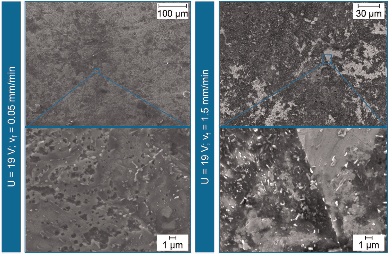
Surface of specimen machined in 12 wt % sodium chloride electrolyte at 36 °C and different feed rates (SE picture, performed on Jeol JSM-7000F at 15 kV).
According to Figure 5, lower feed rates lead to pitting corrosion localized over the surface homogeneously. The diameter of the pittings varies in the range from sub-micrometer to a few micrometers. At higher feed rates, almost no more single pits can be recognized, leading to two possible statements. Either the surface is a superposition of pitting holes or due to the higher dissolution rate there is no time for the development of pitting corrosion. The overall surface roughness is slightly better for NaCl electrolytes compared to NaNO3 electrolytes, going along with the provided statements of a more homogeneous dissolution of different grain types. 9 Therefore, it is shown that either the surface roughness or the surface integrity strongly depends on used electrolyte salt. For a comprehensive process signature, the chemical loading causing the variation of manufactured surface has to be modeled in detail.
Selective dissolution
Most of common alloys, besides single crystal materials, have a variety of grains within the material structure. The amount of different grain species within the microstructure again is determined by the chemical composition of the alloy and the previous heat treatment process. In dependence of their composition, the chemical stability of these different grain types deviates a lot. Thus, they are dissolved at different rates during ECM.
Applying this approach to steel 42CrMo4 with a ferrite-perlite microstructure, the ferrite grains are dissolving much faster according to equations (3)–(5). In a perlite grain instead the cementite can either be chemically dissolved or can be flushed out as a nobler phase 23
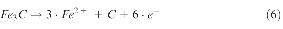
Due to this, the differences in the electrochemical dissolution rate change the local composition of the material on one hand and on the other hand these differences can determine the surface roughness. 24 Thus, depending on the size of the grain lamellae, the surface roughness increases significantly (Figure 6).
Ferrite depletion influencing the surface topography of 42CrMo4 specimen machined in 20 wt % NaNO3 electrolyte at 36 °C (BSE-SEM picture, performed on Jeol JSM-7000F at 15 kV).
From Figure 6, it is evident that the one material phase lamellae rise above the surface. Due to this, the concentration of noble phase increases directly at the surface, while less noble material is depleted. In addition, as there is no phase change during the manufacturing process, the surface topography as well as the roughness is determined by the initial size of the grains. Thus, this effect will be much smaller at quenched and tempered steel. Due to this, the achievable surface roughness in ECM strongly depends on the manufacturing history as this sets up the microstructure of the workpiece. 2
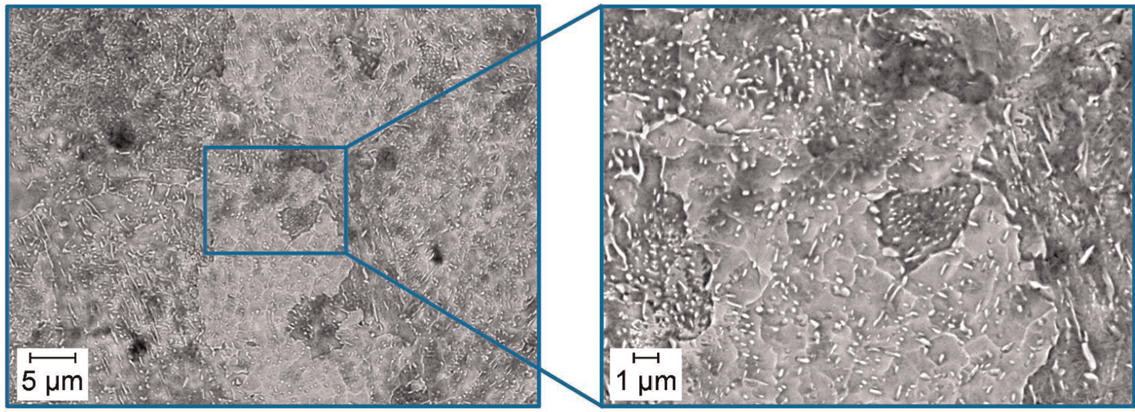
For the identification of the phases, additionally energy-dispersive X-ray (EDX) measurements in the bulk material were performed. Due to the measurement principle, it is not possible to perform these measurements directly at the machined surface. For this reason, cross section of machined specimen was manufactured and afterward the EDX measurements were performed at the polished surface of the cross section (Figure 7).
Ferrite depletion influencing the surface topography of 42CrMo4 specimen machined in 20 wt % NaNO3 electrolyte at 36 °C (EDX measurements).
Figure 7 shows the left side the view on 45° tilted specimen with the surface in the lower part and the polished cross section in the upper part. Due to different excitation energies of the different atom species, it is not useful to determine the carbon and chromium content simultaneously. Therefore, the upper measurement in Figure 7 shows the carbon X-ray intensity along the line scan and the lower measurement shows the chromium X-ray intensity along one line scan. Due to these measurements and the SEM figures, the conclusion can be drawn that the nobler phase is cementite or another carbide-rich material phase. Finally, it can be stated that the differences in electrochemical stability of material phases determine the surface roughness and integrity.
Conclusion and outlook
A major advantage of ECM is that the manufacturing process is free from mechanically damaged or thermal influenced rim zone. Nevertheless, even in ECM, the rim zone and its properties are changed during the process. Therefore, this article presented four major material modifications caused by the manufacturing process, namely, flow grooves, oxidation, pitting corrosion, and selective dissolution. In addition, the origin of these phenomena and the material loadings producing the changes were discussed and analyzed for steel 42CrMo4. Thus, it was shown that the occurrence of flow grooves cannot solely be attributed to the electrolyte flow. Instead, the flow interacts with the chemical dissolution reaction leading to local variation of dissolution rate and due to that this interaction determines the surface topography.
Further influence of rim zone modifications occurring during ECM to surface integrity and components functionality was examined. For instance, it was shown that the inherent passive layer of ECM processes does not improve the corrosion behavior of components in all cases. Finally, the interaction of ECM processes and workpiece microstructure was examined by means of two examples. Nevertheless, the overall influence of ECM to workpiece rim zone is quite small and can additionally be minimized by understanding the main active working principle. A comprehensive process signature will map these effects and give the chance to forecast rim zone properties. Thus, the introduced modifications will be examined more in detail and modeled based on the different material loadings occurring during the process.
Footnotes
Acknowledgements
The authors wish to thank the German Research Foundation (DFG) for funding the Collaborative Research Center SFB/TRR 136 “Function Oriented Manufacturing Based on Characteristic Process Signatures” (Bremen, Aachen, Oklahoma), subprojects F03 and C02.
Declaration of conflicting interests
The author(s) declared no potential conflicts of interest with respect to the research, authorship, and/or publication of this article.
Funding
The author(s) received no financial support for the research, authorship, and/or publication of this article.