
Abstract
Difficult-to-machine 508III steel is widely applied in the water-chamber heads of steam generators for nuclear power stations of AP1000 nuclear islands. The dominant machining process for these components is heavy-duty cutting. Since 508III endures significant mechanical impacts and alternating thermal loads during milling, the cutting temperature is relatively high. High temperatures reduce the surface quality of the workpieces and accelerate insert wear, which shortens the insert service life and reduces cutting efficiency. In this article, the welding set and amplifying circuit of thermocouples were designed. Coated cemented carbide inserts were adopted. The wired half-artificial thermocouple method was utilized to conduct 508III steel milling temperature tests. The influence regularity of cutting parameters on the milling temperature was analyzed, and the regression model of the milling temperature was constructed, which provided boundary conditions for insert simulation analysis. Second, finite element simulations of the milling process and milling inserts were carried out to analyze the temperature variation regularity and insert temperature distribution during milling. The simulation results were compared with the experimental results for validation. Finally, the wear behavior of the 508III milling insert was characterized by analyzing the wear condition of both the rake surface and flank surface of the milling insert, as well as the wear amount of the flank surface. The interactive influence regularity between the insert wear and milling temperature was explored. The milling temperature distribution and insert wear state obtained from the simulation agreed with the experimental results. The availability and reliability of the designed milling temperature test system were validated, which provides theoretical foundations and technical support for developing inserts and improving the cutting efficiency of difficult-to-machine materials.
Introduction
Difficult-to-machine 508III steel has superior weldability, favorable resistance to neutron irradiation embrittlement, good fracture, and impact toughness. Thus, it is widely used in the production of forgings such as the heads, flanges, and end sockets of pressure vessels for nuclear islands. 508III is a low-carbon alloy steel that has good strength, favorable low-temperature impact resistance, and a low non-plastic transition temperature. 1 Cutting large water-chamber heads requires extreme super-heavy-duty cutting, the cutting depth and feed rate of which are usually 10 times greater than those of conventional cutting. However, the forging process of water-chamber heads usually leads to forging defects such as pits, cords, and wrinkles on the billet surface, which often leads to non-uniform cutting depth, large cutting force fluctuation, and high cutting temperatures (as high as 1000 °C) in successive milling processes. 2 Moreover, to improve steel hardenability, the substrate must be intensified and weld sensitivity must be reduced without affecting stability and usability; to this end, iron alloy elements with siderophile affinity such as Mn, Ni, and Mo are typically added. These alloy elements combined with non-metallic elements including B and C and formed hardening phases with high melting points, as well as intermetallic compounds with high toughness. Thus, the cutting resistance during milling increased, resulting in improved cutting temperatures. Massive cutting heat concentrated in the cutting zone affects the layers and residual stresses in the processed surface. Thus, the inserts are prone to wear. 3 Also, iron-group elements including Co in cemented carbide inserts used in 508III milling are easily softened in high temperature and pressure environments due to their strong affinity to congeners. Furthermore, insert-chip adhering and insert back-cutting phenomena can also occur, which leads insert fractures. 4 Jawaidy et al. 5 and De Melo et al. 6 studied that the hierarchical structure of coated tools and bond, wear, diffusion, plastic deformation, and hot crack of workpieces were a major cause for coated tool wear. However, these are mostly resulted from cutting heat. Besides, abrupt flaking that occurred on the tool rake face was mainly caused by the increase in tool temperature, mechanical impact, and thermal impact.7,8 Therefore, the high temperature generated from machining difficult-to-machine material has significant influence on tool wear.
At present, there are some temperature measurement approaches, including the embedded thermocouple, infrared photography, infrared thermometer, ultrasonic-assisted method, and metallographic structure method.9,10 Drilling a hole that is greater than the thermocouple wire, to a certain extent, changed the normal deformation process of cutting material in the embedded thermocouple method. The material deformation, friction, and heat transfer in high temperature are different from the normal cutting state. So, using infrared photography method is not accurate for measuring the milling temperature. In addition, infrared thermometer is hard to determine the coordinate position of test points in the cutting zone. Shi et al. 11 measured the relative temperature and temperature field during aluminum alloy milling by using an infrared radiant energy thermometer. However, the relative temperature did not precisely reflect the actual milling temperature. Liu et al. 12 transmitted signals produced by a rotator via wireless communication and conducted a series of tests to calibrate system accuracy. Afterward, they measured the cutting temperature of a rotating workpiece. After the contrast analysis of the measuring temperature method, temperature field distribution in cutting zone in a semi-artificial thermocouple method conform to the measurement results of the real milling conditions. 13
Investigations concerning cutting temperatures have primarily focused on cutting temperatures under continuous and steady cutting conditions. Most studies focused on ordinary cutting conditions with conventional aluminum alloys and structural carbon steel. Experimental studies and theoretical analyses of the cutting temperature distribution features are currently insufficient, especially in the heavy-duty milling of difficult-to-machine materials such as 508III and 2.25Cr-1Mo-0.25 V.14–17 High temperatures usually occur during the milling of difficult-to-machine materials. High cutting temperatures lead to transformation and the over-heating of surface metallurgical structures, accelerate insert wear, shorten the insert service life, and reduce cutting efficiency. Therefore, investigating the cutting temperature distribution and insert wear mechanism during 508III milling has significant importance in optimizing cutting parameters and improving processing quality and machining efficiency. Moreover, they are meaningful to the processing and manufacturing of difficult-to-machine materials.
Experimental study and simulation analysis of 508III steel milling temperature
Experimental study on 508III steel milling temperature
Experimental material and setup.
The experimental material was 508III steel, which is widely applied in the water-chamber heads of vapor generators of AP1000 nuclear plants. The water-chamber heads are connected to other vapor generator components via welding. To strengthen the matrix, improve hardenability, and reduce weld sensitivity, iron-group elements including Mn, Ni, and Mo are often added into 508III.18,19
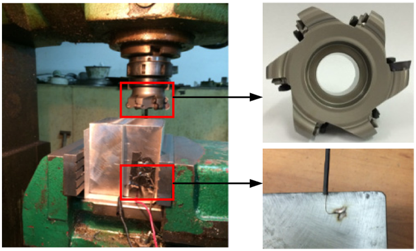
As shown in Figure 1, this experiment used an XW5032 vertical knee-and-column type miller, an FMR04-100-B32-RD16-06 cutter head with 100 mm in diameter and 6 teeth, and WIDIA-cemented carbide circle inserts RDMT1605MOTX-TN6540 coated by TiAlN. 508III workpieces with dimensions of 100 mm × 100 mm × 100 mm were milled. In fact, the workpiece has been cut into two pieces to install thermocouple wire.
The milling experimental facility.
Thermocouple installation and welding device design.
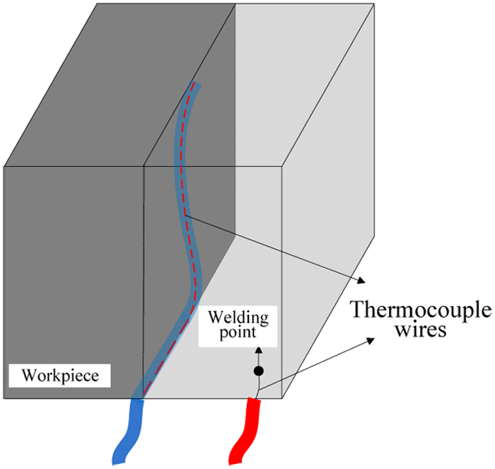
Based on comparative analysis of different cutting temperature measurement approaches, the milling temperature was measured using the wired semi-artificial thermocouple method. The Ni-Cr wire of a standard thermocouple was fixed between workpieces, and insulating treatments were carried out between thermocouple wires and workpieces, as well as workpieces and the miller. The other thermocouple wire was welded on the workpiece end far away from the cutting zone as shown in Figure 2. During milling, when the insert cuts the thermocouple, the insulation layer between the workpiece and the thermocouple wire was destroyed, and hot points formed instantly between the thermocouple wire and workpiece. Thus, a semi-artificial thermocouple was constructed, and thermal electromotive force was generated. So, the temperature measured is similar to that of the position where the insert touched the thermocouple wire.
Thermocouple installation position.
Since welding approaches including electronic spot welding, oxyhydrogen welding, arc welding, and tin soldering result in low welding quality, high costs, complex operations, low safety standards, and strong metal material selectivity, a more practical high-voltage welding apparatus was designed (Figure 3 shows the schematic diagram and real object).
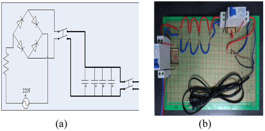
High-voltage welding device: (a) the schematic diagram of the welding equipment and (b) the real diagram of the welding equipment.
Experiment results and analysis.
According to the milling parameters obtained from on-site investigations of water-chamber heads, a Taguchi L9 was used to cut the 508III. Table 1 shows the factor level used in the experiment. During the experiment, dry milling was conducted, and the cutting type was inverse milling.
Level of factors used in experiments.
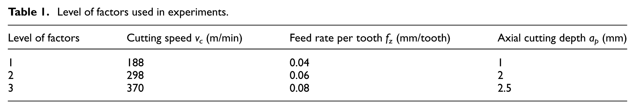
Figure 4 shows the thermocouple signals collected during milling. The process parameters were as follows: cutting speed 298 m/min, axial cutting depth 2.5 mm, radial cutting depth 80 mm, and feed rate per tooth 0.06 mm/tooth.
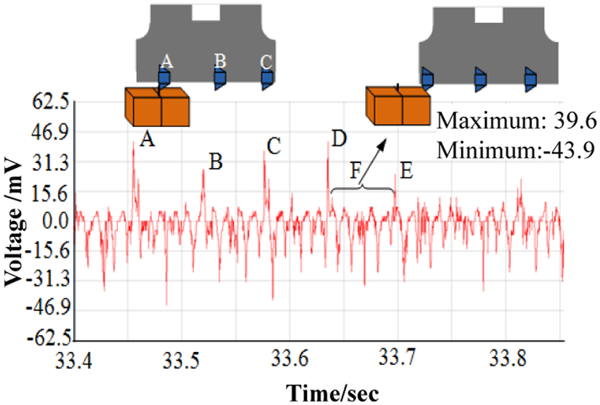
Thermal potential signal diagram obtained during the milling experiments.
The six milling inserts were defined as A, B, C, D, E, and F, respectively. Since the thermocouple wire was soft, it was difficult to break all at once during milling. Thus, thermal electric potential signals corresponding to the moments of A, B, C, D, E, and F inserts cutting into the thermocouple wire can be seen in Figure 4. It was demonstrated that the strength of signal E was obviously lower than those of A, B, and C; this is attributed to the fact that after the former inserts were cut, the short thermocouple wire remained insulated with the workpiece. Curve F was the potential signal between the workpiece and the thermocouple wire. The time interval between A and B was 33.523 s − 33.466 s = 0.063 s. The time interval between B and C was 33.582 s − 33.523 s = 0.061 s. The time interval between C and D was 33.647 − 33.582 s = 0.065 s. Due to the existence of problems in the signal disturbance, apparatus response, and data processing, there were errors in the time interval of the measured signals, but the error amplitudes were still within an acceptable range.
After acquiring thermal potentials by measuring the milling temperature with the wire semi-artificial thermocouple method, the milling temperature was obtained by calibrating the thermocouple signals collected by the non-standard thermocouples based on the comparison method. Table 2 is the 508III milling test table based on the Taguchi L9 method.
Experiment table of milling 508III steel based on Taguchi L9.
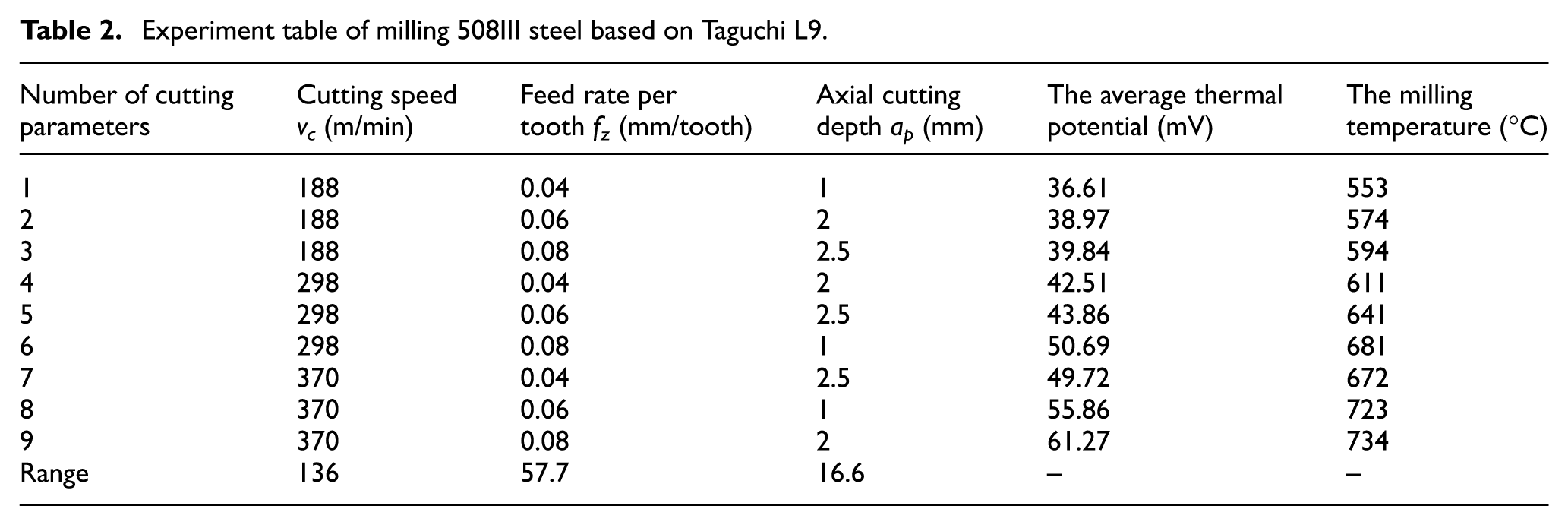
As shown in Table 2, since 508III has strong thermal conductivity, poor thermal diffusivity, and small specimen dimensions, the temperature deviation between the hot-end and cold-end was small after one milling cycle. Hence, the milling temperature measured during the experiment was comparably low. According to the calculated data range, the cutting speed had the most significant influence on milling temperature, followed by the feeding rate, while the axial cutting depth had the least influence.
Practical formula for milling temperature.
At present, studies on the practical formula for 508III milling temperatures are still lacking. Through the following solving method, a practical formula 20 for 508III milling temperature can be obtained
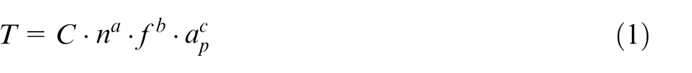
where C is a constant, n is the rotation speed, f is the feed rate per tooth, and ap is the axial cutting depth. The coefficients a, b, and c are the index of rotation speed n, feed rate per tooth f, and axial cutting depth ap, respectively.
By taking the logarithm of equation (1)
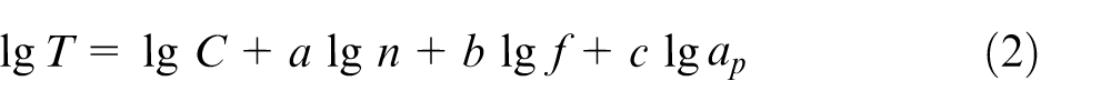
Equation (2) can be considered as a function with a, b, and c as its independent variables, while lgT as the dependent variable
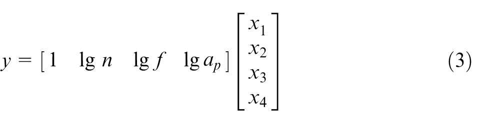
where x1 = lgC, x2 = a, x3 = b, and x4 = c.
Based on Table 2, a regression function can be acquired via MATLAB
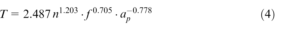
By transforming equation (4) into the form of cutting speed
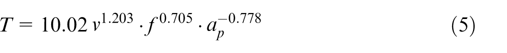
The practical formula of 508III milling temperature obtained above can not only provide foundations for the calculation of milling temperature but also provide boundary conditions for the finite element simulation of insert temperature fields during 508III milling.
Finite element simulation of the 508III milling process
To demonstrate the temperature variation regularity during 508III milling more intuitively, a DEFORM–three-dimensional (3D) finite element simulation system was adopted to simulate the whole process. Milling temperatures and related variation tendencies under various parameter conditions were collected.
During simulation, a WIDIA-cemented carbide circle insert similar to that used in the experiments was utilized. The Lagrange algorithm was applied to calculate the milling process. To ensure the effectiveness of the simulation, the geometrical model of the workpiece was simplified before simulation, as shown in Figure 5.
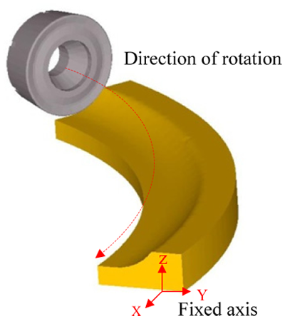
Milling geometrical model.
A number of mesh elements directly decided the model shape, simulation efficiency, and calculation accuracy. According to the dimensions of the workpiece and insert, as well as the properties of simulation computers, a mesh refining was made in the initial contact area between the insert and workpiece. Meanwhile, meshes in the areas with relatively concentrated stresses, that is, a high calculation data gradient variation, such as in the area around the cutting edge and the deformation zone, were also refined. To reduce the model scale, other areas with small gradient variations were coarsened to obtain high-quality meshes. By taking advantage of the DEFROM-3D automatic mesh generation and mesh adaptive technology, the entity models of the insert and workpiece were meshed. Afterward, local refining was conducted, and the cutting edge area was meshed more intensively.
The boundary conditions of the workpiece and insert should be set during milling simulation. Referring to practical milling conditions, the X, Y, and Z directions of the workpiece were fixed. Because the actual diameter of cutter head is 100 mm, this insert is set to rotate around the cutter center as shown in Figure 5. The initial milling temperature of both the workpiece and insert was set to 20 °C. Simulation conditions were need to be set for simulating the milling process.
The Finite element simulation will begin after setting the total number of operational steps as 3000 steps and saving data every 25 steps. With the process of cutting the metal, the work of tool overcoming the plastic deformation of the workpiece material and the heat generated by friction between tool–chip contact surface and tool–workpiece contact surface will partly pass to the tool and the workpiece.
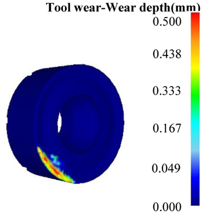
During cutting, some of the heat generated by the work performed by the insert to overcome the workpiece elastic–plastic deformation and the friction between the chip–insert and insert–workpiece interfaces was then transferred to the insert and workpiece. Figure 6 displays the insert cutting temperature distribution and related variation regularity under the cutting parameter of vc = 370 m/min, fz = 0.08 mm/tooth, and ap = 2 mm found by computer-aided calculation. Figure 7 shows the insert wear condition.
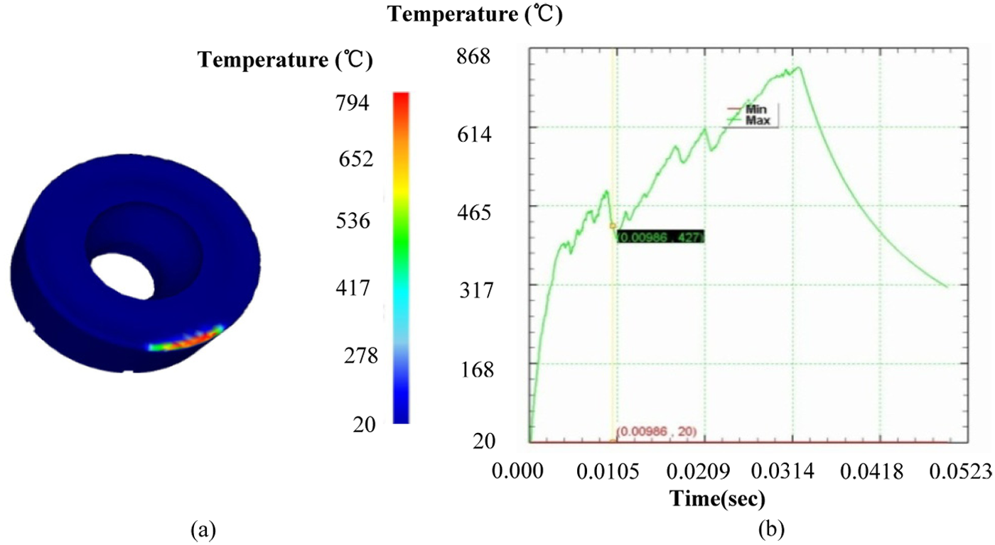
The insert cutting temperature distribution and related variation regularity: (a) cutting temperature distribution of milling insert and (b) temperature trend during cutting process.
Simulation analysis of the insert rake face wear.
As shown in Figures 6(a) and 7, the insert nose near the flank face suffered the most serious wearing during the simulation. This portion had the strongest friction and the highest heat generation. However, since it had a relatively large contact interface, the temperature was not the highest. As for the rake face, which contacts chips off and on, the friction heat continuously accumulated in the insert–chip contact area and had highest local temperature due to the intense friction, small contact area, limited heat radiating area, and inhibited heat emission. According to Figure 7, this area also suffered from serious wear. Moreover, it can also be found that the cutting temperature–affected zone was limited in a very small rake face–chip contact zone, as well as a small area around the cutting edge, while the cutting temperature increased little in areas not involved in cutting. In these areas, which were far away from the major cutting edge, the milling temperature presented a gradient distribution. The simulation results in Figure 6(b) reveal that at the beginning of milling, the cutting force increased and the workpiece temperature sharply increased. The cutting speed slowly improved, the material shear angle increased, the cutting deformation coefficient decreased, and the insert–chip friction factor decreased. Most of the cutting heat was taken away by the chips, and the increasing temperature trend stabilized. The high temperature reduced the cutting force by softening the workpiece material. Thus, the cutting temperature decreased. Afterward, the hardness of the cooled workpiece increased, which again resulted in an increase in cutting force and the related cutting temperature. Thereby, the cutting temperature experienced a seasonal variation.
To validate the relationship between the experiments and simulation for milling cutters, a milling simulation of 508III was carried out with cutting parameters similar to those of the experiment. The temperature simulation results were averaged and compared with the experimental results, as shown in Figure 8. The horizontal coordinate shows nine groups of cutting parameters in Table 2.
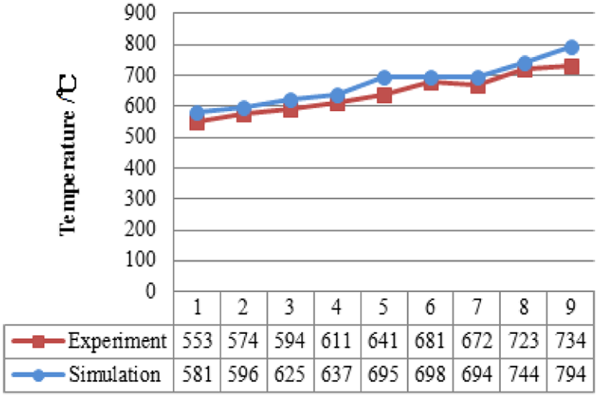
The comparison of temperature experiment and the simulation results of milling cutter in milling 508III steel.
As shown in Figure 8, due to the relatively small dimension and poor heat dissipation performance of the 508III workpiece during milling temperature tests using the wired semi-artificial thermocouple method, the cold-end temperature of the semi-artificial thermocouple was relatively high. Thereby, the collected thermal potential difference was small, and the acquired experiment temperature of milling cutters was lower than the simulation temperature. However, the deviation between the experimental and simulation results was still small and acceptable.
In addition, the milling temperature results of the experiment and simulation demonstrate that the strengthening phases of the alloying elements often decomposed from the solid solutions at high cutting temperatures and distributed in the workpiece matrix in the form of very fine dispersion phases. Hence, the surface strength and hardness of the workpiece were further increased, which accelerated the wear of hard material on the insert surface and led to direct contact between the insert matrix and chips. Thus, adhesion occurred, which led to insert failure. 21 After the cutting edge became dull, the compressive stress that was applied on the insert increased. The increase in friction between the workpiece and flank face further aggravated the milling temperature increase. Thus, it is necessary to investigate the interactive influence regularity between the cutting temperature and insert wear during 508III milling.
A study on the tool wear behavior of milling 508III steel
Rabinowicz et al. 22 pointed out that the friction in a unit cutting distance and unit area is
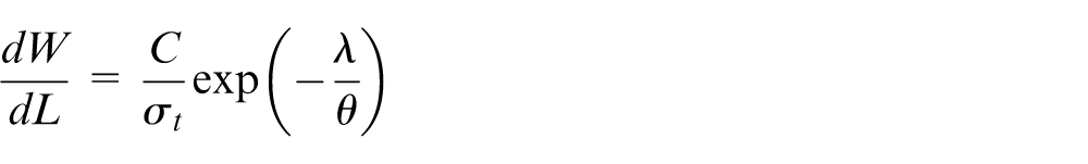
where σt is the normal stress, θ is the temperature, λ and C are the wear characteristic constants related to insert and workpiece materials, respectively.
According to the above equation, the insert wear is directly related to pressure and temperature and usually the combined results of mechanical, thermal, and chemical actions. During milling, large compression and serious friction exceeding the material yield strength existed between the workpiece and flank face, as well as the chip and rake face. High temperatures were introduced in the contact surface, which led to adhesion. Due to the relative motion between friction pairs, the adhered part was taken away by one side. Thus, wear occurred. In addition, at high temperatures, Co in the cemented carbide insert quickly diffused into the chips and workpiece. WC decomposed into W and C, which diffused into the steel. The reduction of the adhesion phase Co further reduced the adhesion strength of the hard phases (WC and TiC) in the cemented carbide. C and W from chips and the workpiece moved into the cemented carbide and formed new complex carbides with low hardness, which also enhanced insert wear. The higher the milling temperature, the greater the diffusion coefficient and the more serious the diffusion wear. To reduce and control insert wear, as well as decrease the milling temperature of 508III, it is necessary to study the cause and essence of insert wear during 508III milling.
The wear morphologies of the inserts during 508III milling can be divided into rake face wear and flank face wear. A super field-depth microscope was adopted to characterize the wear conditions of both the rake face and flank face after various milling durations. The wear value of cutter is the average wear width in even wear belt. Figure 9 displays the results. The process parameters were as follows: cutting speed of v1 = 188 m/min, v2 = 298 m/min, and v3 = 370 m/min; axial cutting depth 2 mm; radical cutting width 80 mm; and feed rate per tooth 0.08 mm/tooth.
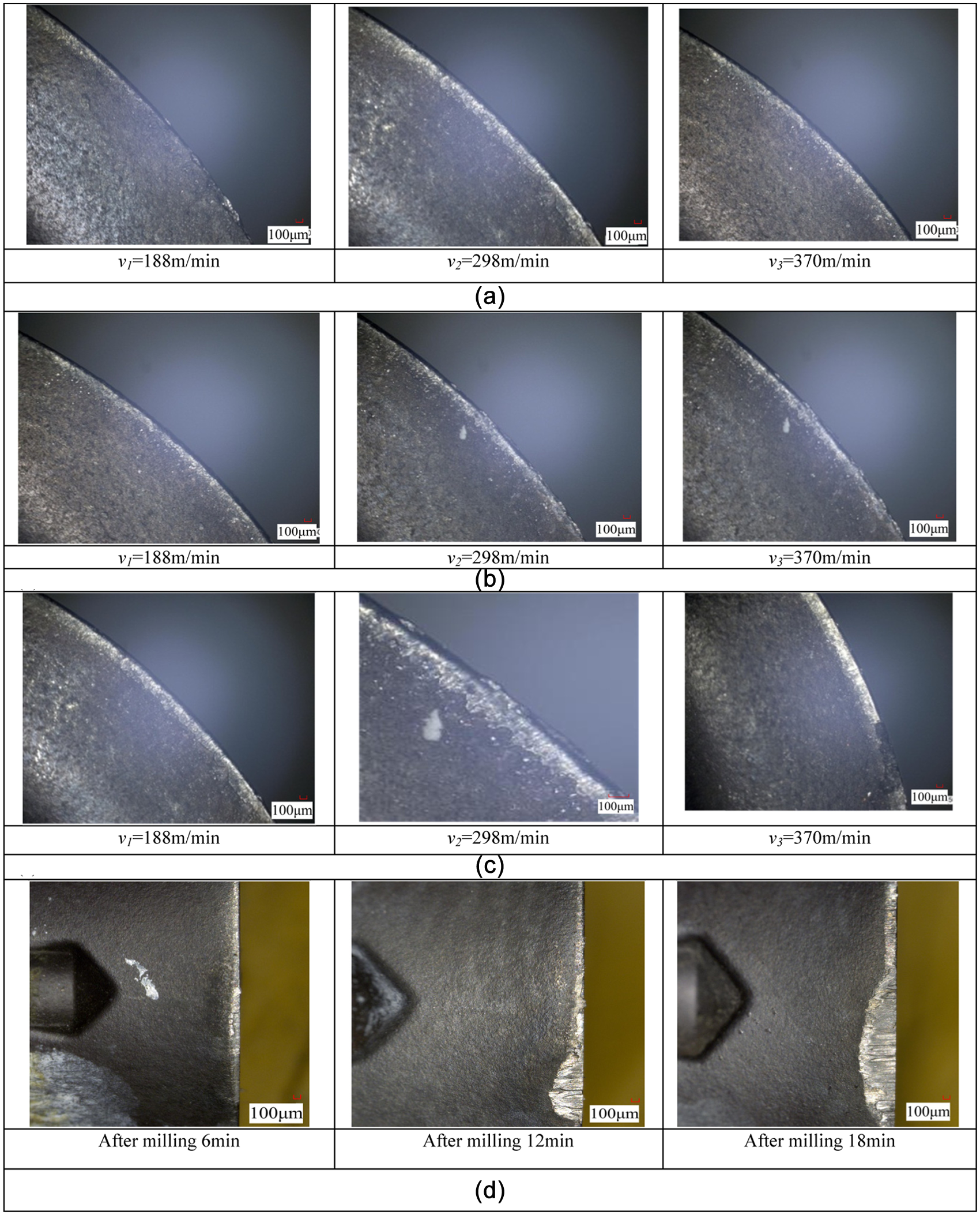
The wear condition of both rake face and the flank face in milling 508III steel: (a) wear condition of the rake face after 6 min, (b) wear condition of the rake face after 12 min, (c) wear condition of the rake face after 18 min, and (d) wear condition of the flank face in speed of v3.
Due to friction between the rake/flank faces, chips, and the workpiece during milling, and the high temperature and pressure in the cutting zone, wear with various degrees occurred on the rake/flank faces of the milling insert. Since the chemical composition of the 508III was comparably active, it was prone to react with chemical elements in the circle milling insert. Besides, since the milling temperature was high, the wear of the rake/flank faces was serious. As shown in Figure 9(a)–(c), the TiAlN-coated insert wore after 6 min of milling, and the wear aggravated after 12 min and became serious after 18 min. Figure 9(c) demonstrated that under the cutting speed of v3 = 370 m/min, the cutting temperature was high, and the resistances to heat and friction were reduced. Crater wear with an average width of 178.09 µm occurred after 18 min. Since fierce friction existed between the processed surface and the flank face, serious non-uniform wear occurred on the flank face (as shown in Figure 9(d)), which agrees with the simulation results. There are many grooves and pits in the worn area, which continuously reduced the keenness of the cutting edge. Hence, under a cutting speed of v3 = 370 m/min and a cutting duration of 18 min, there was serious crater wear on the rake face, while obvious non-uniform wear was found on the flank face. The wear became more serious and the crater width gradually expanded as the milling duration increased. Thus, the cutting edge strength fell sharply, which increased the likelihood of tipping to occur. Hence, when milling 508III steel using coated cemented carbide inserts, the cutting speed should be lower than 370 m/min to ensure the service life of the inserts.
The measurement of insert wear, especially that of the flank face wear, is the dominant standard to evaluate the insert wear and durability. Since the cutting speed has the most significant influence on durability, a super field-depth microscope was utilized to characterize the flank face wear after different milling durations under various milling conditions. The milling parameters were set as milling speed of v1 = 188 m/min, v2 = 298 m/min, and v3 = 370 m/min; feed rate per tooth of fz = 0.08 mm/tooth; axial cutting depth of ap = 2 mm; and radical cutting width of ae = 80 mm. The measurement time intervals at both the initial wear stage and fierce wear stage were relatively shorter than those at the normal wear stage. Figure 10 shows the relationship between the flank face wear degree and milling duration under different cutting speeds.
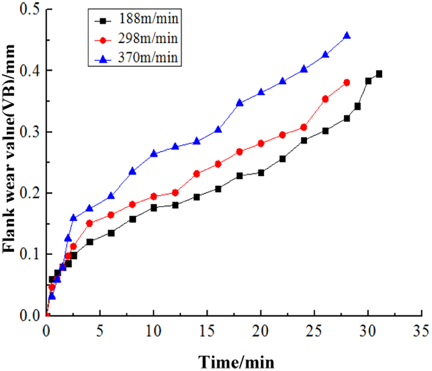
Flank face wear degree curve under different cutting velocities.
As shown in the Figure 10, when the cutting speed changed, the flank face wear curve varied correspondingly. The curves experienced the wear starting stage, wear developing stage, and fast wear stage. If the insert wear limit was 0.3 mm, the corresponding insert durability was T188 > T298 > T370 (T188 stands for the insert durability under the cutting speed of 188 m/min; the others refer to 298 m/min and 370 m/min, respectively). Referring to the correspondence relationship of each curve, it can be found that T188 was about 28 min, T298 was 24 min, and T370 was 15 min. Hence, the insert service life under the cutting speed of v1 = 188 m/min differed little from that of v2 = 298 m/min. By selecting the cutting speed of v2 = 298 m/min, both the insert service life and cutting efficiency can be improved.
Figure 11 shows the relationship between the flank face wear degree and temperature under different cutting velocities. The temperature is the max value in same period of time.
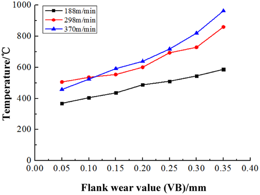
The relationship between the flank face wear and cutting temperature.
As shown in Figure 11, under the same wear degree, the greater the cutting speed, the higher the cutting temperature will be. When the flank face wear is weak, the temperature variation is flat. With the increase in wear degree, the milling temperature variation rises. When the flank face wear reaches 0.15 mm, the temperature increases 3%–4%, which becomes 9%–15% when the flank face wear reaches 0.35 mm. Therefore, it is revealed that after the insert wear increases, the cutting temperature quickly rises, which further affects the insert service life. Moreover, high cutting temperatures also lead to the variation or even burn of processed surface metallurgical structures, which thereby affect workpiece manufacturing accuracy.
Conclusion
This article focused on the difficulty in temperature measurement during milling the difficult-to-machine 508III steel, designed a milling temperature measurement system, and conducted related experiments. Based on the finite element simulation of milling temperatures, the reliability of the experiment design was validated. The interactive influence regularity between the insert milling temperature and insert wear was discussed. Based on these research results, the following conclusions can be drawn.
Through the design of a thermocouple welding device and amplification circuit, the temperature measurement tests of 508III milling were carried out by using the wired semi-artificial thermocouple method, with the thermal potential signals obtained. By analyzing the obtained milling temperature, the milling speed was found to have the most significant influence on milling temperature, followed by the feeding rate; the axial feeding depth had the least influence. A practical prediction formula to determine milling temperatures was established, which provides foundations for milling temperature prediction and provides boundary conditions for the milling insert temperature distribution.
By conducting simulations of the milling process and thermal–mechanical coupling analysis of the insert, a periodic variation regularity of the milling temperature was obtained, presenting a variation tendency of increasing fast, rising slow, reducing, and increasing again. The temperature in the cutting area presented a graded distribution. The chip–insert interface had the highest temperature, and the farther away from the cutting area, the lower the temperature. The temperature in the non-chip–insert contact area changed little. The simulated milling temperature and insert wear morphology agreed with those of the experimental results, which not only intuitively reflected the cutting temperature variation regularity but also provided effective verifications for the reliability of 508III experimental studies.
Based on the measurements of the rake/flank face wear morphologies, and the flank face wear regularity, serious wear with different degrees occurred on both the flank and rake faces during milling. With the increase in milling speed, the wear of the flank/rake faces became more serious. Reducing the cutting speed inhibited the expansion of crater wear on the rake face, thereby increasing the insert durability but reducing cutting efficiency. The cutting speed should be lower than 370 m/min when using coated cemented carbide inserts to cut 508III steel. When the cutting speed was 289 m/min, both the cutting efficiency and insert life were improved.
Studies of the interactive influence regularity between insert wear and milling temperature demonstrated that when the flank face wear was weak, the temperature variation was smooth. As friction increased, the milling temperature changed more significantly. When the flank face wear reached 0.15 mm, the temperature increased 3%–4%, which became 9%–15% when the flank wear was 0.35 mm. After the insert wear was aggravated, the cutting temperature increased more quickly. High cutting temperatures affected the insert service life in return.
Footnotes
Declaration of conflicting interests
The author(s) declared no potential conflicts of interest with respect to the research, authorship, and/or publication of this article.
Funding
The author(s) disclosed receipt of the following financial support for the research, authorship, and/or publication of this article: This work was supported by the National Natural Science Foundation of China (51675145), the Science and Technology Key Projects of Heilongjiang Province Department of Education (12541z006), and the Research and Development Project of Applied Technology of Harbin (2014DB4 AG017).