
Abstract
Thermal errors are one of the most significant factors that influence the machining precision of machine tools. For large-sized gear grinding machine tools, thermal errors of beds, columns and rotary tables are decreased by their huge heat capacity. However, different from machine tools of normal sizes, thermal errors increase with greater power in motorised spindles. Thermal error compensation is generally considered as a relatively effective, convenient and cost-efficient approach in thermal error control and reduction. This article proposes two thermal error prediction models for motorised spindles based on an adaptive neuro-fuzzy inference system and support vector machine, respectively. In the adaptive neuro-fuzzy inference system–based model, the temperature values are divided into different groups using subtractive clustering. A hybrid learning scheme is adopted to adjust membership functions so as to learn from the input data. In the particle swarm optimisation support vector machine–based model, particle swarm optimisation is used to optimise the hyperparameters of the established model. Thermal balance experiments are conducted on a large-sized computer numerical control gear grinding machine tool to establish the prediction models. Comparative results show that the adaptive neuro-fuzzy inference system model has higher prediction accuracy (with residual errors within ±2.5 μm in the radial direction and ±3 μm in the axial direction) than the support vector machine model.
Keywords
Introduction
As the demand for machine tool accuracy increases, a lot of research work has been conducted in the field of error compensation. Generally, errors of machine tools can be divided into the following three categories: 1
Geometric and kinematic errors;
Thermal errors;
Force-induced errors.
Among these errors, thermal errors account for about 40%–70% of the total errors according to Bryan’s 2 research. Thermal errors are generally caused by expansion, contraction and distortion of machine tool components, resulting in asymmetries and deformation of machine tool frames. These asymmetries and deformations are the main principle factors that limit geometrical position accuracy and machining performance of machine tools. Especially for the gear grinding process, a highly geometrical sophisticated process, machine tool position accuracy is more important for keeping the grade of machining precision. The optimisation of thermal design is a method conducive to minimising the influence of deformations on geometrical position accuracy. For example, symmetry in column, base and table structure geometry and location of heat sources will help minimise distortions. Also, machine tool structures should be designed to keep position errors caused by machine structure deformation away from machining sensitive directions. For a specific computer numerical control (CNC) gear grinding machine, motorised spindle is a core component that drives the grinding wheel and performs feed motion to remove materials. In the process of gear grinding operations, motorised spindles would generate a large amount of heat. Therefore, the thermal properties of motorised spindles have a great impact on the processing quality and machinery efficiency of gear grinding operations.
For a certain motorised spindle, the bearings and built-in motor generally produce a large amount of heat, which results in complicated thermal characteristics. For example, the heat generated can cause elastic thermal deformation of motorised spindle components. Additionally, the uneven temperature field may lead to distortion of arbour. The distortion is detrimental to machining accuracy. In order to reduce the influence caused by the thermal error of the motorised spindle on the machine tool accuracy, relevant research is focused on the following categories: 1
Thermal error avoidance;
Thermal error control;
Thermal error compensation.
Thermal error avoidance focuses either on heat generation reduction or thermal deformation by replacing bearing materials with advanced materials, such as aluminium alloys, ceramic materials and carbon fibre–reinforced plastics. This results in a lower coefficient of thermal expansion. Thermal error control focuses on minimising the effects of thermal deformation by incorporating the cooling jackets around the motorised spindle or transferring thermal deformation into the direction that is not so sensitive to machine accuracy. The strategy of thermal error compensation is to compensate the thermal error by adjusting the position of the cutting tool or workpiece. In the process of thermal error compensation, the most important thing is to establish a prediction model for thermal errors. Then, compensation measures should be taken to counteract, homogenise and reduce deformation induced by heat.
In academic research and engineering practice, it is very difficult to obtain accurate analytical results of thermal errors since the structure of motorised spindles is complex and the spindle temperature fields are variable. Therefore, in the last decade, research on thermal error compensation of motorised spindles was generally based on two schools of thought. The first method is a numerical analysis of temperature fields and thermal errors, in which the adopted approaches include the finite element method (FEM), 3 finite difference method (FDM) 4 and finite difference element method (FDEM). 5 Haitao et al. 6 and Uhlmann and Hu 7 proposed thermal models of high-speed motorised spindles based on FEM. They both presented methods to compute the heat generated by bearings and built-in motors, and the convective heat transfer coefficients. However, they did not consider the thermal characteristics of bearings and the influence of the thermal shift of angular contact bearings. The stiffness and damping of bearings keep changing as the temperature rises. Holkup et al. 8 presented a FEM-based thermo-mechanical model for spindles. They studied temperature distribution and thermal growth of motorised spindles. Bearing stiffness and contact load under specific operating conditions were considered in their research. Specially, they estimated the changes in the dynamic behaviour of spindles in terms of bearing properties. To simulate the thermal-induced deformation of high-speed spindles, Ma et al. 9 took thermal contact resistance (TCR) and bearing stiffness into consideration. The model considering TCR and bearing stiffness has improved the simulation precision of thermal deformation. Nonetheless, their research only focused on a certain high-speed spindle system. Above all, for thermal error modelling based on numerical analysis, the biggest challenge is to establish boundary conditions and obtain accurate heat transfer coefficients. However, no widely accepted method has been proposed to calculate these parameters accurately.
The second method is empirical modelling based on correlation analysis and soft computing, such as regression analysis, 10 artificial neural networks (ANNs),11–13 grey system theory, 14 support vector machines (SVMs)15,16 and hybrid models.17–19 Hao et al. 20 developed a thermal error model of a turning centre. Using a genetic algorithm–based back-propagation neural network (GA-BPN), they reduced the diameter error of workpieces from 27 to 10 μm. Yang et al. 16 proposed a thermal error model of high-speed motorised spindles based on least squares support vector machines (LS-SVM). In their studies, the thermal error model and thermal error compensation system were established on a precision CNC jig boring machine. The result showed that the axial maximum error decreased from 39 to 8 μm. Abdulshahed et al. 21 presented a thermal error model of CNC vertical milling machine based on the adaptive neuro-fuzzy inference system (ANFIS). In their research, the model had high prediction accuracy and the residual error (RE) was smaller than 4 μm. Compared with temperature sensors, thermal imaging cameras generally have lower measurement accuracy, which may affect prediction precision of their model. In addition, the model was compared favourably against a model based on ANN.
This article focuses on a motorised spindle used in a large-sized CNC gear grinding machine tool. Thermal balance experiments were conducted using thermal sensors and laser displacement sensors. To compensate thermal errors, prediction models based on ANFIS and SVM are proposed, respectively. This article is organised as follows. First, the theoretical backgrounds of ANFIS, SVM and particle swarm optimisation (PSO) are introduced briefly in section ‘Thermal error modelling’. Second, thermal error models are established in section ‘Thermal error modelling’. For ANFIS modelling, subtractive clustering and gauss curve membership function (MF) are found to be the optimum choices for the training process; for SVM modelling, PSO is adopted to obtain the optimum values of parameters C, ε and σ. Third, section ‘Experiments setup’ presents thermal balance experiments based on the training data and testing data. Finally, prediction results are compared and discussed in section ‘Results and discussions’, and conclusions are drawn from the previous parts in section ‘Conclusion’.
Thermal error modelling
Theory of ANFIS
The ANFIS was first introduced by Jang, 22 which is a hybrid neuro-fuzzy technique that brings ANN to fuzzy inference systems (FISs). The ANFIS combined the well-established learning rules of ANN and the linguistic transparency of fuzzy logic within a single framework. In recent decades, ANFIS has been widely used as an attractive modelling technique for the prediction and controlling system. Abdulshahed et al.21,23 presented thermal error compensation models of CNC vertical milling machines based on ANFIS-Grid and ANFIS-FCM (fuzzy c-means), and the models showed good predicting performance. The typical structure of ANFIS is shown in Figure 1. The function of each layer is shown as follows. 22
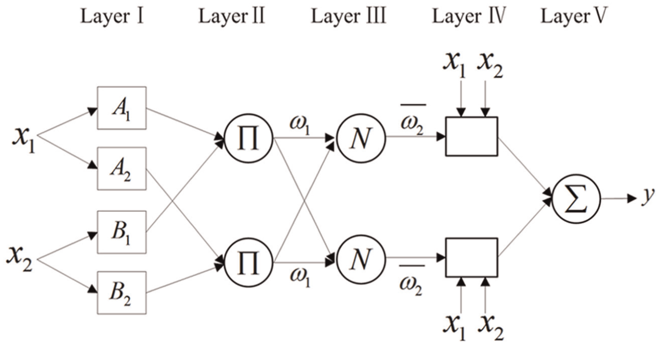
Typical structure of ANFIS.
Layer 1 is fuzzification layer, in which fuzzification operations are executed. The node in this layer is called adaptive node as indicated by the node functions. The node functions are defined by


where
Layer 2 is the fuzzy rule layer. Fuzzy rules are conducted in this layer. The node in this layer is represented by Π, the output of this layer is given by

Layer 3 is the normalisation layer. MFs are normalised in this layer. The node in this layer is represented by N
where
Layer 4 is the defuzzification layer. Consequent parts of fuzzy rules are executed in this layer. Nodes in this layer are adaptive nodes, which are obtained by

where
Layer 5 is the output layer. The overall output is described as
Modelling based on ANFIS
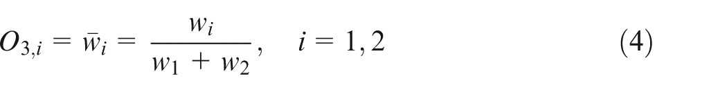
In the ANFIS-based thermal error model (Figure 2), in order to reduce the number of fuzzy rules, subtractive clustering method (SCM) is used to optimise the fuzzification. For the SCM, each point of the data array is assumed as a potential cluster centre. Initially, the objective function-density of other points around the considered one can be calculated. Then, the point with the maximum value of objective function-density is selected as the first cluster centre. After selecting the first cluster centre, another cluster centre ought to be chosen until the possibility of every point is below the threshold set.
Architecture of the ANFIS model.
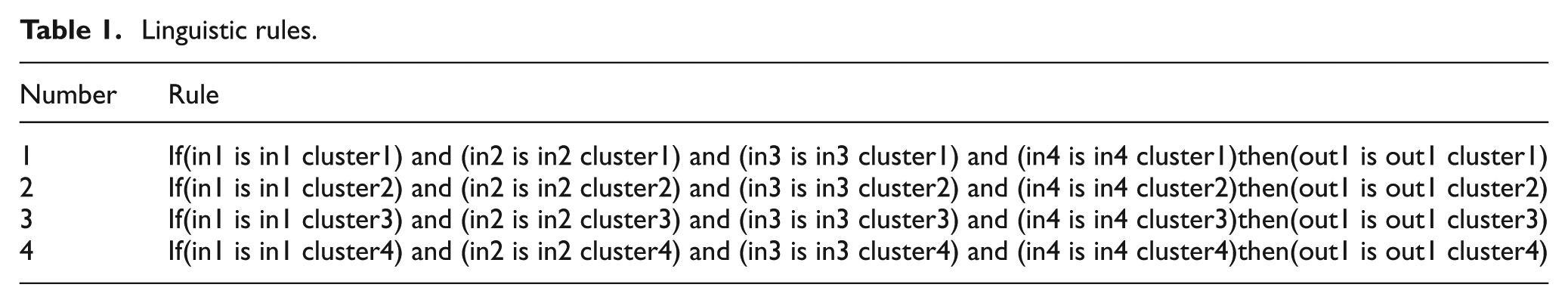
The performance of ANFIS is highly related to the MFs since the adjustments of MFs enable the system to learn from the input data. In this model, Gaussian MF (gaussMF) was selected as the MF after several trails. Parameters associated with Gaussian MFs change with the learning process, and the parameters are adjusted by the hybrid learning scheme. Compared with the back-propagation (BP) learning scheme, the hybrid learning scheme can accelerate the convergence speed of the model, lower training error and improve estimation accuracy. Figure 3 shows the curves of MFs obtained by the optimisation procedure. Besides, the number of training epochs is closely associated with the performance of ANFIS.
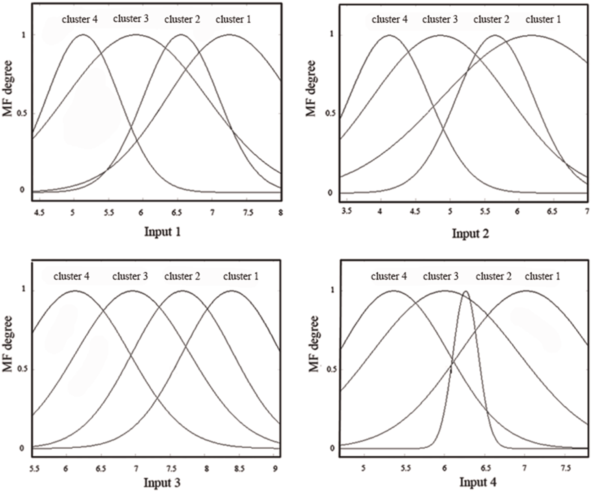
Curves of membership functions.
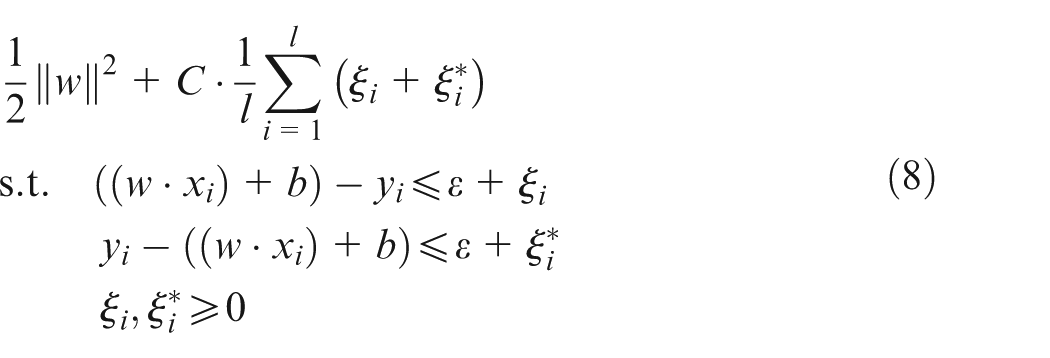
In this model, the number of clusters was found at 4. During the training process, training error converged until the number of training epochs reached 200. After several runs, the model exhibited best with four clusters. Moreover, the FIS with four linguistic rules was considered optimal. The corresponding linguistic rules are shown in Table 1.
Linguistic rules.
Theory of PSO-SVM
SVM is a supervised learning method based on statistical learning theory. Following the principle of structural risk minimisation (SRM), SVM has good generalisation ability. In recent years, due to its competent ability to solve learning problems, SVM has been widely used in many fields, such as prediction, pattern detection and classification. For regression problems, SVM is also called support vector regression (SVR). The theory of SVR is developed as follows: let us consider a set of training data

where
For nonlinear regression problems, the key issue is to introduce a characteristic function to map the input variables into a high-dimensional feature space. Hence, the nonlinear regression problem is converted into a linear one. The characteristic function is also called the kernel function, denoted as
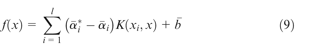
where
PSO is a population-based iteration optimisation algorithm, which is put forward by Kennedy. 24 Inspired by the optimisation procedure in social behaviour of bird groups, PSO does not require that the optimised function possesses be differentiable, derivable and continual. Therefore, it can be applied to a variety of problems, especially discontinuous, non-differentiable and multimodal problems.
In the initial stage of PSO, a set of particles searches for the optimal solution of random positions in the problem space. Similar to the preying behaviour of a flock of birds, each particle has a random velocity at the outset. A fitness function is defined on a particle’s location.
The optimisation target is to find the position that has the best fitness function values. After each iteration, each particle’s velocity is updated according to its fitness. The particle’s new velocity depends on its current velocity, the distance from its own best position and the global best position. Both the velocity and the location of the particles are updated in the iteration process. The velocity and position of each particle are calculated as follows
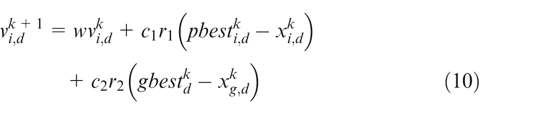
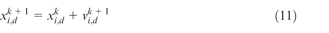
where
Steps of the PSO algorithm are generally defined as follows:
Step 1: Initialise each particle.
Step 2: Calculate the fitness value of each particle.
Step 3: Compare the fitness value obtained in Step 2 with the best fitness value (pbest).
Step 4: Set the better fitness value as the new pbest.
Step 5: Choose the particle with the best fitness value as the gbest.
Step 6: Calculate particle velocity and position according to equations (10) and (11).
Step 7: Return to Step 2 if the number of maximum iterations or minimum error criteria is not attained; otherwise, stop the iteration and save the results.
Compared with the genetic algorithm (GA), PSO does not have crossover or mutation operation. Consequently, it has faster convergence speed, low algorithm complexity and strong robustness.
Modelling based on PSO-SVM
In the SVM model, training data with proper parameters are necessary for obtaining a near-fact representation of the thermal deformation process. In this model, the Gaussian radial basis function (RBF) kernel is chosen as the kernel function for its better performance; the kernel function is formulated as
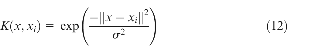
Different sets of parameters C,
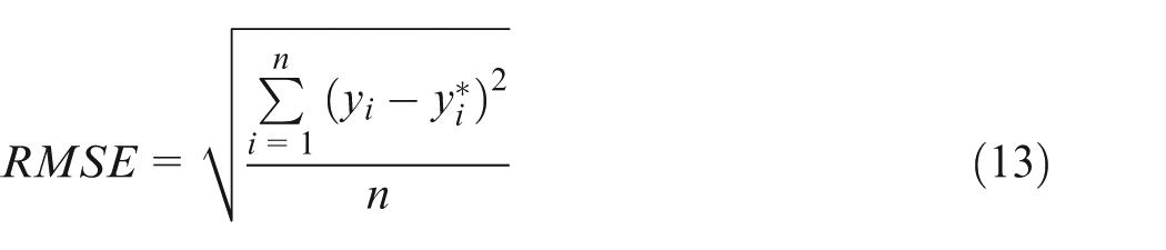
The flow chart of this model is shown in Figure 4. In order to get better prediction performance, a simple scaling operation (normalisation) is applied to training and testing data, as suggested by Cherkassky and Ma. 25 The SVM network is responsible for prediction. However, due to a wide search range, it is time-consuming to search the optimum parameters. Although some researchers 26 introduced techniques based on experimental data to determine the ranges of these parameters, parameter optimisation is still needed in the SVM model. PSO searches for the optimum C, ε and σ by comparing the prediction errors in each iteration. The chance of generalisation error is reduced in SVM learning. The parameters must be tuned in such a mode that can reduce training errors in the learning process. The fitness functions adopted in this article are root-mean-square error (RMSE) and determination coefficient (), which are defined in equations (13) and (14).
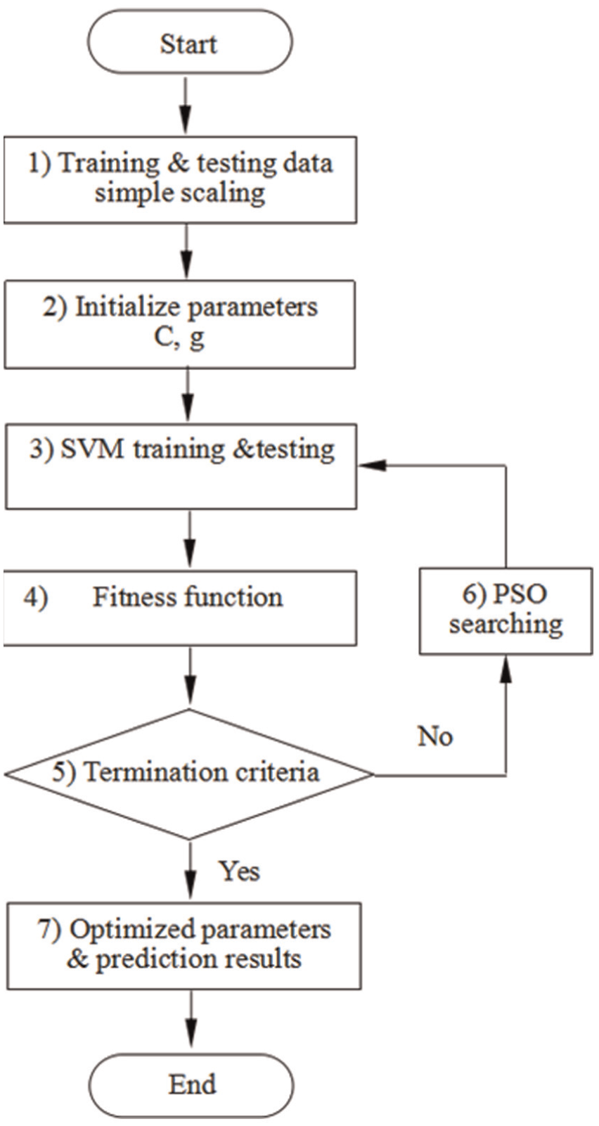
The flow chart of the PSO-SVM model.
The minimisation of RMSE is carried out for the selection of parameters C, ε and σ. A value of 0 for RMSE indicates that the prediction performance has the best performance. A value of 1 indicates that the regression curve fits the data exactly. During the minimisation procedure of RMSE, different sets of C, ε and σ reshape the regression surface. To avoid infinite iterations of parameter searching in PSO, the maximum number of iterations is set as 150 with 20 particles. Optimisation starts with random values for each parameter. The PSO-SVM model will run along with the optimisation of parameters C, ε and σ. The optimal values of C, ε and σ in the PSO-SVM models are shown in Table 2.
Optimised parameters of the PSO-SVM model.
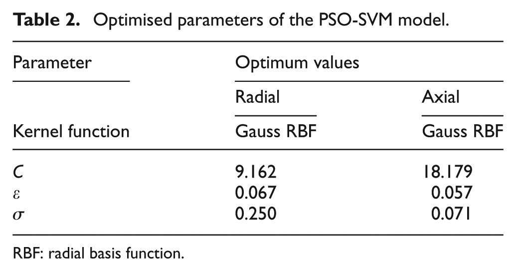
RBF: radial basis function.
The models were performed with SVR-ε in MATLAB 2012a using the LIBSVM library. 25 The computer environment was as follows: Intel® Core™ i5-4460, 3.2 GHz of CPU, 4 GB of RAM, Windows 7 64 bit operating system.
Experiments setup
In order to develop a thermal error compensation system, thermal balance experiments are conducted on the motorised spindle of a large-sized CNC gear grinding machine. Training and testing data are obtained from these experiments under different conditions. In addition, this section compares the spindle thermal errors in radial and axial directions.
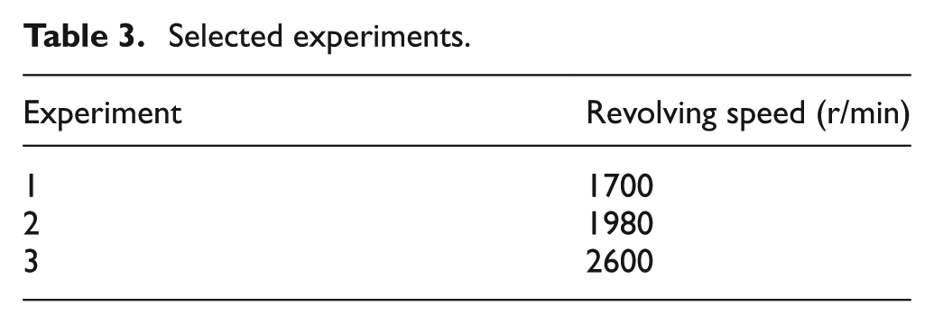
Validation experiments are carried out on the same CNC gear grinding machine to evaluate the proposed models. As shown in Figure 5, six thermal sensors are used to measure the temperature fluctuations of the motorised spindle. The mounting positions of thermal sensors are determined by the structure and the heat sources of motorised spindle. Generally, motor and bearings are considered as the main sources of generated heat in the motorised spindle. In this study, the mounting positions of thermal sensors are based on previous research work. The mounting positions of thermal sensors are as follows: rear bearings (Sensor 1), spindle pedestal (Sensor 2), spindle motor (Sensor 3), front bearings (Sensor 4), machine tool column (Sensor 5) and ambient (Sensor 6). As shown in Figure 6, in order to monitor the spindle thermal drifts, two laser displacement sensors are fixed in the axial and radial directions, respectively, of the spindle. Validation experiments are carried out under air load conditions at different revolving speeds. As listed in Table 3, three experiments are selected to build and test the model. Data obtained in experiment 1 are chosen as the training data; data of experiments 2 and 3 are chosen as the testing data.
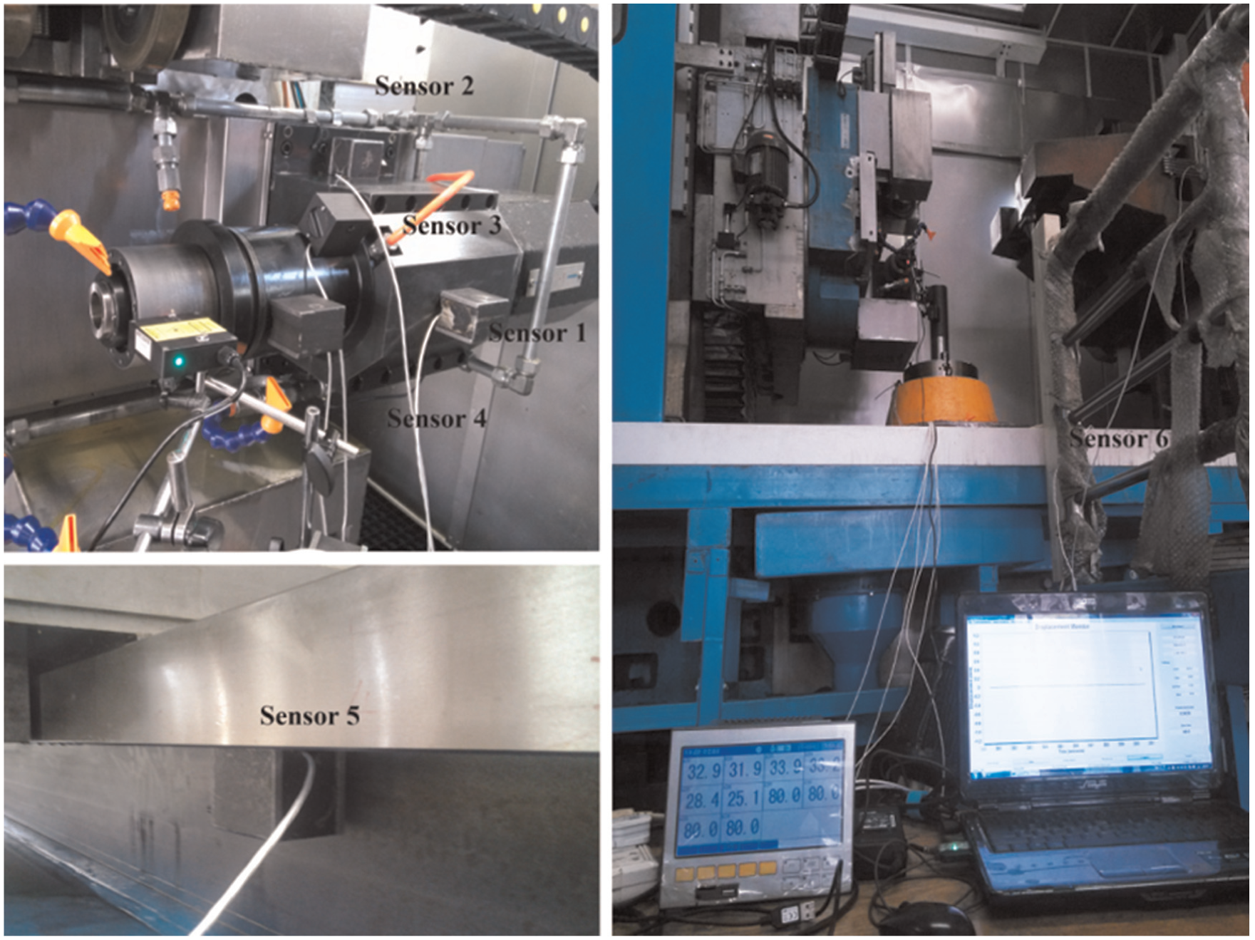
Temperature sensors installation.
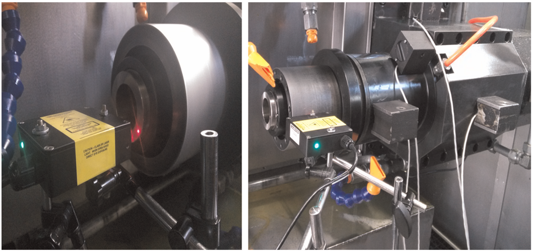
Laser displacement sensors installation.
Selected experiments.
In experiment 1, obtained temperature and temperature changes in selected temperature sensors are shown in Figures 7 and 8. In this study, temperature changes are chosen as the four inputs of the thermal error prediction model. Figure 8 indicates that data 1–4 are equal to the temperature of sensors 1–4 minus that of sensor 5. Thermal errors in radial and axial directions are shown in Figure 9, which shows that the radial errors are much greater than the axial errors in this experiment; the stable values of radial and axial thermal errors are 29 and 11 μm, respectively.
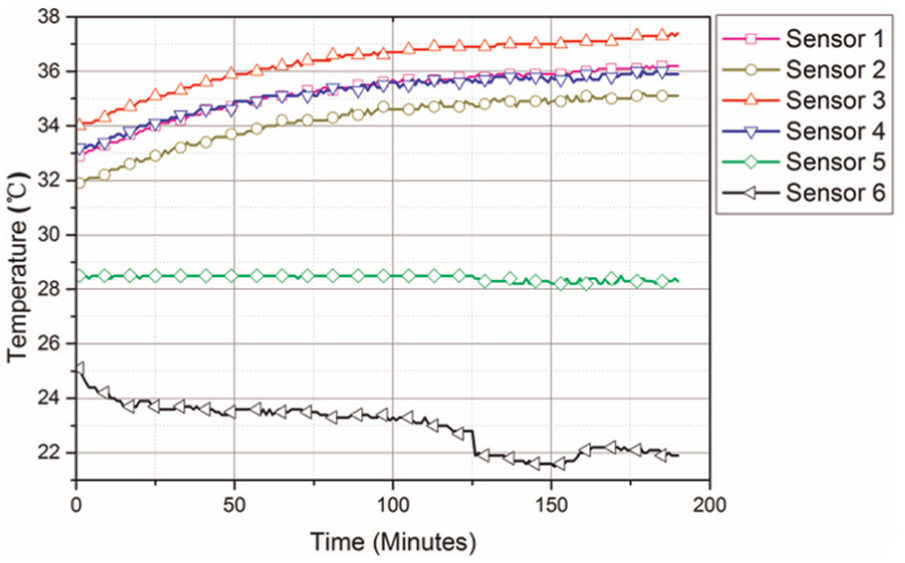
Temperature of selected sensors.
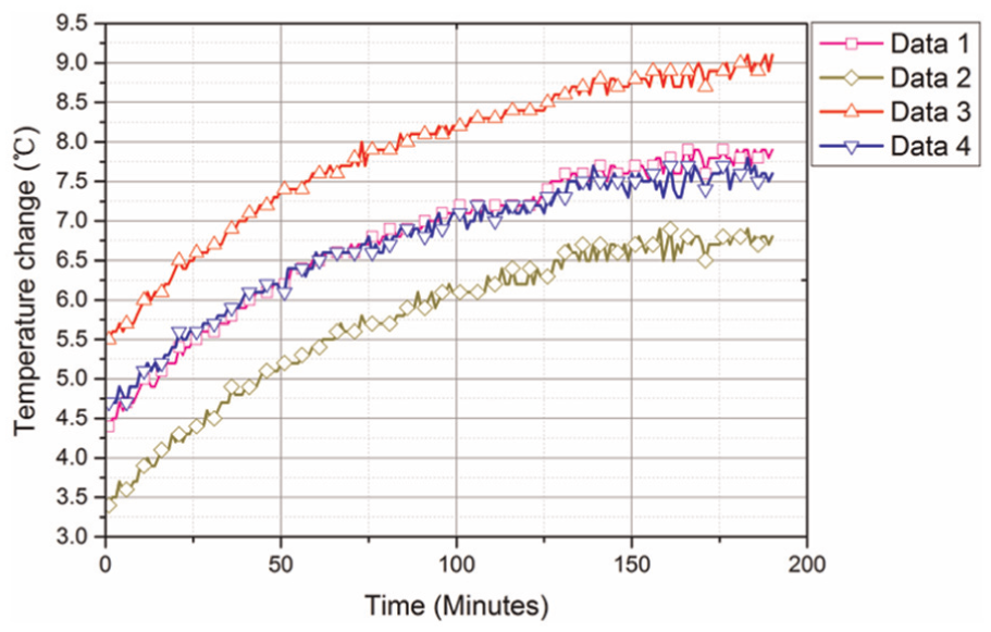
Temperature changes in the spindle.
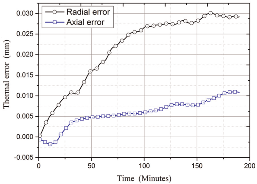
Thermal errors of the spindle in experiment 2.
Results and discussions
This section aims to compare the prediction results of the proposed models with experimental thermal errors, as well as to evaluate the prediction performance of the ANFIS-based model and the PSO-SVM-based model. In this study, we adopt three evaluation criteria to compare the prediction performance of the proposed models: RMSE, determination coefficient
The RMSE is defined as
The
The RE is defined as

where
The comparison of radial thermal error in experiment 1, prediction results of the ANFIS-based model and RE is shown in Figure 10. The stable prediction value reaches 27 μm, and the maximum RE is less than ±3 μm. The radial thermal error, prediction results of the PSO-SVM-based model and the corresponding RE are shown in Figure 11. The results show that prediction thermal error reaches 30 μm, and the RE is within ±4 μm. By comparing the two figures, it indicates that the ANFIS-based model has better prediction performance than the model based on PSO-SVM.
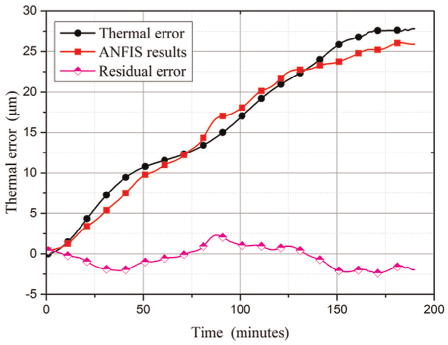
ANFIS prediction results of radial thermal errors.
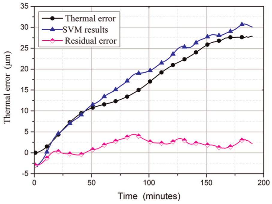
PSO-SVM prediction results of radial thermal errors.
The comparison of axial thermal error in experiment 3, prediction results of the ANFIS-based model and RE is shown in Figure 12. The results show that the stable value of prediction reaches 11 μm, and the RE is within 4 μm. The prediction results of the PSO-SVM-based model and the RE are shown in Figure 11. The prediction error reaches 10 μm, and the maximum RE is ±4 μm. In Figures 9, 12 and 13, it is noteworthy that there is a downward phase before the rising phase along the curve of axial thermal errors and the trend of this curve is different from the curve of radial thermal errors. To the best of our knowledge, this phenomenon is seldom mentioned in other articles. The principle of the aforementioned phenomenon has yet not been fully studied. The phenomenon may be related to the structure and assembly requirements of the motorised spindle. Generally, in order to keep the accuracy of motorised spindle, the requirements of assembly accuracy of front bearings are higher than that of rear bearings; as a result, the thermal drift of motorised spindle in axial direction is not notable in the initial stage of the temperature rise.
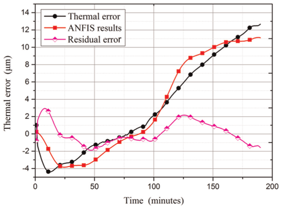
ANFIS prediction results of axial thermal errors.
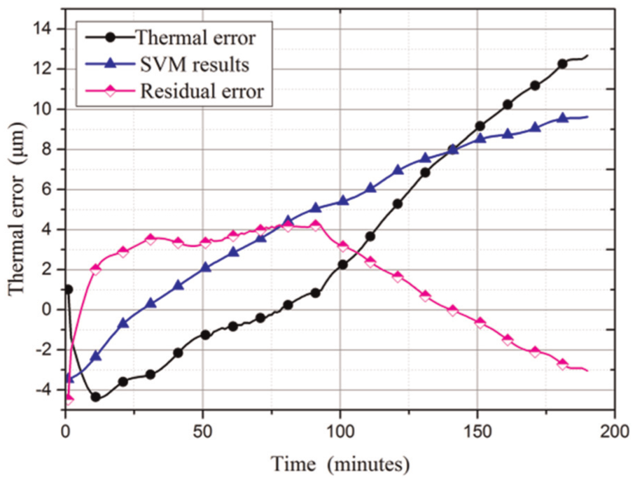
PSO-SVM prediction results of axial thermal errors.
The comparison results show that the ANFIS-based model behaves better than the PSO-SVM model in axial thermal error prediction. The axial thermal errors are more sensitive to the thermal characteristics of the bearing.27,28 Additionally, this complicates the prediction issue. Hence, future research work on thermal characteristics of bearings is needed to obtain more accurate modelling of axial thermal error.
The prediction performance of the two proposed models is shown in Table 4. The results show that these two models are competitive in radial thermal error predictions. In axial thermal error prediction, the ANFIS model is superior to the PSO-SVM model since the prediction results of the ANFIS model are more similar to the process of thermal error changes.
Comparison of evaluation criteria of the models.
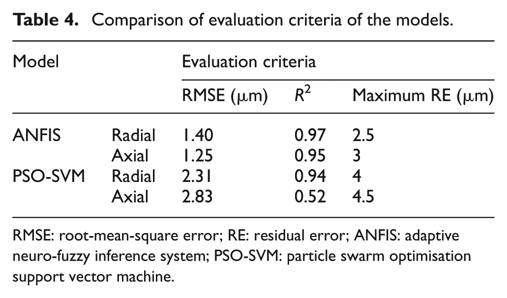
RMSE: root-mean-square error; RE: residual error; ANFIS: adaptive neuro-fuzzy inference system; PSO-SVM: particle swarm optimisation support vector machine.
The main criteria for choosing the ANFIS- or PSO-SVM-based thermal error prediction model can be concluded as follows. An ANFIS exploits the power of verbal descriptions through MFs and inference engines equipped with a rulebase, following the empirical risk minimisation principle. In thermal error modelling, it is seen that ANFIS performs better in terms of providing an accurate fit to the experimental thermal error when having a larger amount of training data. Yet, as a SVM exploits the SRM principle to solve regression problems, it indicates that it is possible to produce relatively reliable prediction results with less training data.
Conclusion
Focusing on motorised spindles in CNC gear grinding machine tools, this article presents two thermal error prediction models based on ANFIS and PSO-SVM, so as to establish the relationship between thermal error and temperature changes. Based on thermal balance experiments, the proposed models can predict radial and axial thermal errors with competitive results.
The two proposed models have been discussed and compared in this article. The ANFIS predicts axial thermal errors and axial thermal errors with the RMSE in 1.40 μm and 1.25 μm, with determination coefficients being 0.97 and 0.95 and 2.31 μm, 2.38 μm, 0.94 and 0.52 for PSO-SVM. It is observed that the ANFIS model demonstrates better performance than the SVM model in the prediction of thermal errors in both radial and axial directions. Besides, both models exhibit better performance in prediction of radial thermal error than that of axial thermal error.
Contributions of this study can be summarised as follows:
As discussed in section ‘Results and discussions’, new problems are found in the thermal error changes of motorised spindles in large-sized CNC gear grinding machine tools.
Using the methods ANFIS and PSO-SVM, two models are established to study the relationship between temperature changes and thermal errors. Compared with the ANFIS-FCM model presented by Abdulshahed, 21 the proposed ANFIS-based model avoids trapping in local optima and reduces the amount of calculation using the SCM method. Simple scaling technique and PSO algorithm are implemented in the modelling of thermal errors based on SVM.
Both of the models proposed can predict thermal errors of the motorised spindle with satisfying results. The prediction results of the two models are also compared according to evaluation criteria. Comparison results show that the ANFIS model performs better in the prediction of thermal errors than the PSO-SVM model.
In conclusion, it can be stated that this article proposes two valid and effective methods to predict thermal errors. By comparison, the ANFIS model is identified to be an economic and prospective alternative for compensating thermal deformation in CNC gear grinding machine tools. Further research can be performed to develop compensation systems of the large-sized CNC gear grinding machine tools.
Footnotes
Acknowledgements
The authors thank Nanjing Gongda CNC Technology Co., Ltd for providing experimental equipment. The authors also express their gratitude to Yang Cao and Lei Ren for their revision of English grammar and spelling of the manuscript.
Declaration of conflicting interests
The author(s) declared no potential conflicts of interest with respect to the research, authorship and/or publication of this article.
Funding
This work was supported by the National Key Technology Research and Development Program of the Ministry of Science and Technology of China (Grant No. 2014BAF08B02), the National Science and Technology Major Project of the Ministry of Science and Technology of China (Grant No. 2015ZX04005003), the Program for Innovative Research Team in University of Ministry of Education of China (Grant No. IRT_15R64) and the Graduate Student Research Innovation Project of Chongqing (Grant No. CYB14009).