
Abstract
Carbon fiber composite materials have been widely applied in national defense fields, including aviation and aerospace, as well as civilian areas, such as automobile, electronic information, and high-speed machinery. During drilling, the cutting force significantly influences the workpiece machining quality and the insert service life. In this article, a simulation study using a polycrystalline diamond insert to drill carbon fiber composite materials was conducted in order to analyze the features of axial drilling force. Drilling experiments were carried out using various cutting parameters, and experimental results were compared to the simulation results. A regression analysis of the experimental data was made, and a cutting force model was constructed. The research results provide a foundation for the parameters optimization of carbon fiber composite material drilling processes.
Introduction
Drilling is one of the major cutting processes for carbon fiber composite materials and accounts for more than half of the total cutting amount. Due to the special mechanical properties of composite materials, the machinability of this kind of material is poor. For example, considerable plastic deformation and manufacturing defects, such as delamination and burr, can easily occur during machining, which then causes serious wear to the inserts as well as affects machining accuracy and efficiency. The drilling force is one of the major parameters during the drilling process, and the magnitude and stability of the drilling force directly determine the quality of the drilled holes. 1
At present, some underlying foundations of the drilling mechanism of carbon fiber composite materials have already been established. For instance, Murphy et al. 2 researched the influence of coatings on the performance of cemented carbide drill during drilling carbon fiber composite material. Arola and Ramulu simplified the cutting process of a unidirectional composite material into an orthogonal cutting model, based on finite element theory. The cutting force values obtained from simulation were compared to experimental values, which indicated that the simulation results were close to the experimental results. 3 By considering the composite material as an isotropic metal material, Zitoune and Collombet established two-dimensional (2D) and three-dimensional (3D) finite element models of composite material cutting as well as analyzed the relationship between the cutting force and fiber direction.4,5 In recent years, more and more drilling models have been developed and applied in finite element analyses. Soldani et al. constructed different drilling models. 6 Santiuste et al. established a 2D finite element model for the cutting of aviation long-fiber composite materials, which mainly contained carbon fiber composites and glass fiber composites. Through finite element calculation, the fiber direction’s influence on axial force and surface quality were characterized.1,7 And some scholars have conducted the research of the cutting force and surface quality during cutting carbon fiber. Wang et al. 8 studied the cutting force in the helical milling of carbon fiber composite material. Brinksmeier et al. 9 studied the cutting force during aviation composite material drilling in addition to its influence on surface integrity. Zhang et al. 10 proposed a mechanical model and studied the prediction of key driving force during composite material drilling. Venu Gopala Rao et al. carried out orthogonal cutting experiments of carbon fiber–reinforced polymer. Based on cutting force analysis, a micromechanical model of composite material processing was constructed. 11 Liu et al. investigated the drilling process of composite materials and proposed measures to increase the drilling efficiency, based on analyzing and calculating the cutting force during carbon fiber composite machining. 12 Tsao and Chen 13 characterized drilled-hole quality and workpiece delamination position. Ma et al. 14 investigated the surface quality characteristics using the ultrasonic assisted turning. Feito et al. 15 studied the cutting force of carbon fiber composite materials and numerically predicted the delamination of workpiece materials. Guo et al. 16 pointed out that cutting force was the main factor affecting the drilling quality of the material and established cutting force model. Chun et al. 17 conducted the drilling experiments of carbon fiber and the research of tool wear and drilling-hole quality.
In this article, the cutting force during carbon fiber composite drilling was investigated based on finite element simulation and experiments, and a regression model of cutting force was established.
Simulation of drilling process
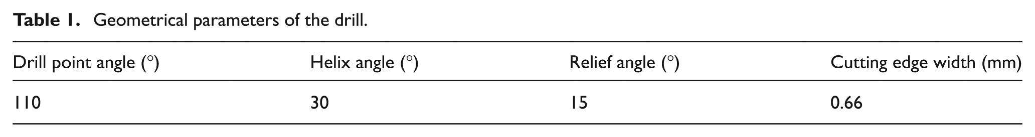
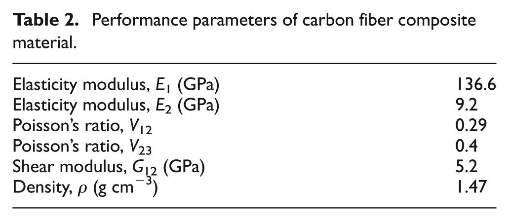
First, related geometrical parameters were defined before simulating the carbon fiber composite drilling process, as shown in Table 1. The diameter of a drilled hole was 7.963 mm. The insert material was diamond, and the insert diameter was 8 mm. The workpiece material was an anisotropic carbon fiber composite sheet, and the material performance parameter is shown in Table 2.
Geometrical parameters of the drill.
Performance parameters of carbon fiber composite material.
The range of spindle speed of computer numerical control (CNC) milling machine was 0–8000 r/min. In the process of drilling experiment of carbon fiber, the selected spindle speed was 2000, 3000, 4000, 5000, and 6000 r/min. According to the commonly used cutting parameters in the actual drilling process of carbon fiber, the feed speed was selected as 150, 180, and 210 mm/min. The carbon fiber drilling simulation was carried out under the same cutting parameters. First, the basic control parameters of the cutting process were determined. The machining type was set as drilling, and the unit was set as SI. The performance parameters of the working environment and machined surface were defined, and the environmental temperature was set as 20 °C, the shear friction factor as 0.6, and the heat conductivity as 15 W/(m K).18,19 The simulation modeling consists of two parts: the modeling of the insert and the modeling of the workpiece surface. In the DEFORM-3D software, geometric primitives were created, with the workpiece diameter set as 15 mm and the thickness set as 5 mm. The drilling 3D models of the drill and workpiece are shown in Figure 1.
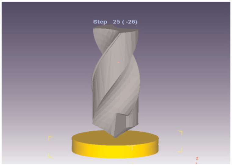
Drilling simulation model.
As for the mesh generation of the carbon fiber composite sheet, the mesh type was set as the absolute mesh density. The minimum element size was set as 0.05 mm according to the feeding speed. For the workpiece without requirement mesh refinement, its dimensional factor was set as the maximum element size. Because an oversized dimensional proportion can potentially result in a sharp increase in the mesh generation time during the simulation, the dimensional proportion was set as 10 in this study. The insert mesh generation was less important than that of the workpiece mesh generation. As a rigid body, the insert shape always kept the contact deformation calculation, and the insert mesh was mainly used for temperature calculation. The mesh type of the workpiece was set with an element number of 20,000.20,21
The axial force (the force parallel to feed direction) was studied with the goal of studying the influence of the axial cutting force on the surface quality of the drilled hole, exit burr, and delamination. According to the simulation results, Figure 2 displays the variation regularity of the axial cutting force when the spindle speed was 3000 r/min and the feeding speed was 210 mm/min. The hole drilling curve can be divided into the following three stages. (1) In the initial stage, the insert came into contact with the workpiece. Since the feeding amount was relatively large and the insert just contacted the workpiece, the insert did not cut the material. The strong influence of the insert on the workpiece resulted in a great magnitude and a rapid increase in the cutting force in the initial stage. The increasing tendency of the axial cutting force in the initial stage was linear. (2) In the second stage, the insert began to cut the workpiece, and the cutting force decreased. After a transient slow changing region, the curve presented an increasing tendency. The variation rate of the axial cutting force after entering the stable cutting stage was relatively smooth. Cutting chips were formed due to the damage and fracture of the carbon fiber composite material, and the axial cutting force varied within a relatively small range. Furthermore, due to the structural particularity of the carbon fiber composite material, the fiber content was large, while the workpiece volume was small. The material nonlinearity resulted in a discontinuity of contact between the insert and the material during drilling as well as a fluctuation in the cutting force. (3) In the last stage, the curve fluctuation became gentle but persistent as the stable-stage drilling proceeded. As the insert penetrated the material, the strain rate greatly changed. When the insert was about to fully cut through the workpiece, the cutting force reached its maximum value, and the curve fluctuation was great. Due to the small insert diameter, large feeding amount, and strong vibration, the adaptive mesh generation (AMG) technology also caused curve fluctuation. The average value (Ave.sim) of the simulated cutting force was 162.7 N.
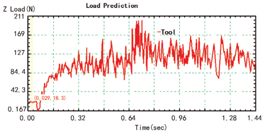
The curves of axial drilling force simulation values.
As displayed in Figure 3(a), the axial cutting force decreased as the cutting speed increased. When the cutting speed is small, the axial cutting force sharply decreased when the spindle speed was increased. The reduction rate of the axial force decreased with a further increase in the spindle speed. When the spindle speed was 6000 r/min, the axial force was about 156 N, which represents a 10% reduction in axial force as compared to when the speed was 2000 r/min. As the feeding speed was increased, the axial force exhibited an increasing tendency, as displayed in Figure 3(b).
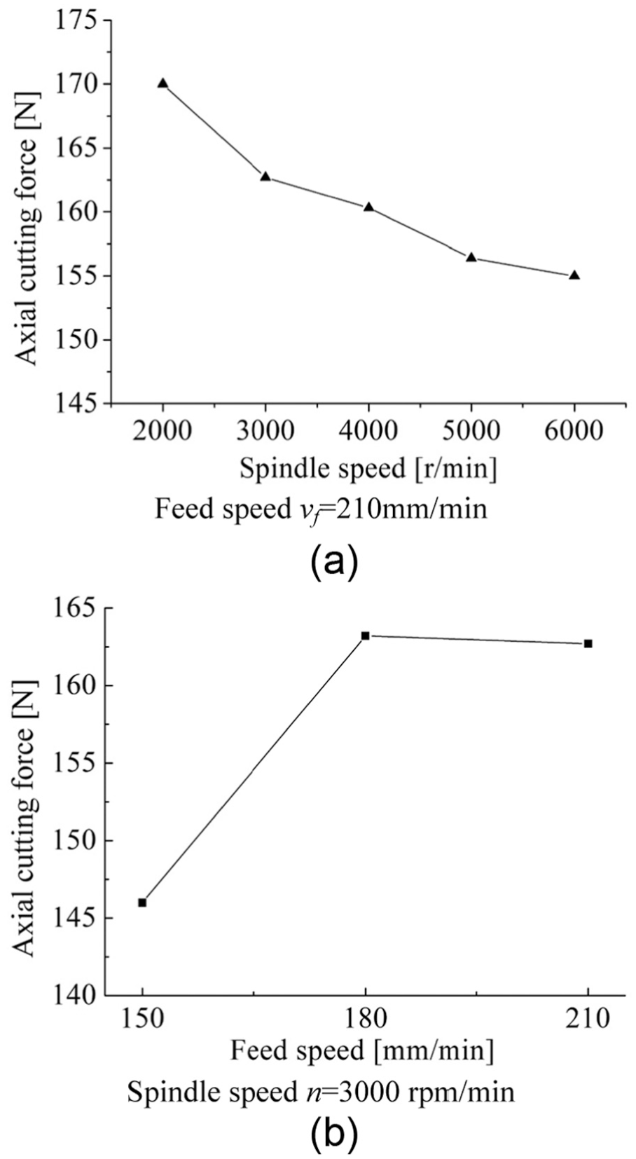
Simulation under different cutting parameters: (a) spindle speeds and (b) feeding speeds.
Drilling experiments
Experimental design
Figure 4 illustrates the self-developed high-speed drilling test system, which consists of two parts: a machine tool and an axial force measurement system. Drilling tests of carbon fiber composite material were conducted by utilizing this system. The machine tool was a three-axis linkage numerical control milling machine VDL-1000E. The axial force measurement system primarily consisted of four parts: a dynameter, a PC, an A/D signal collection card, and a charge amplifier. The dynameter was a Swedish 9275B. The size of carbon fiber sheet was 130 × 100 × 4.5 mm3. As displayed in Figure 4(b), the pressing plate and cushion block were fixed on the dynameter via bolts, and the carbon fiber sheet was clamped between them. Drilling tests were conducted in the center part of the carbon fiber composite sheet. The spindle speed of experiment parameters was 2000, 3000, 4000, 5000, and 6000 r/min. The feed speed was 150, 180, and 210 mm/min.
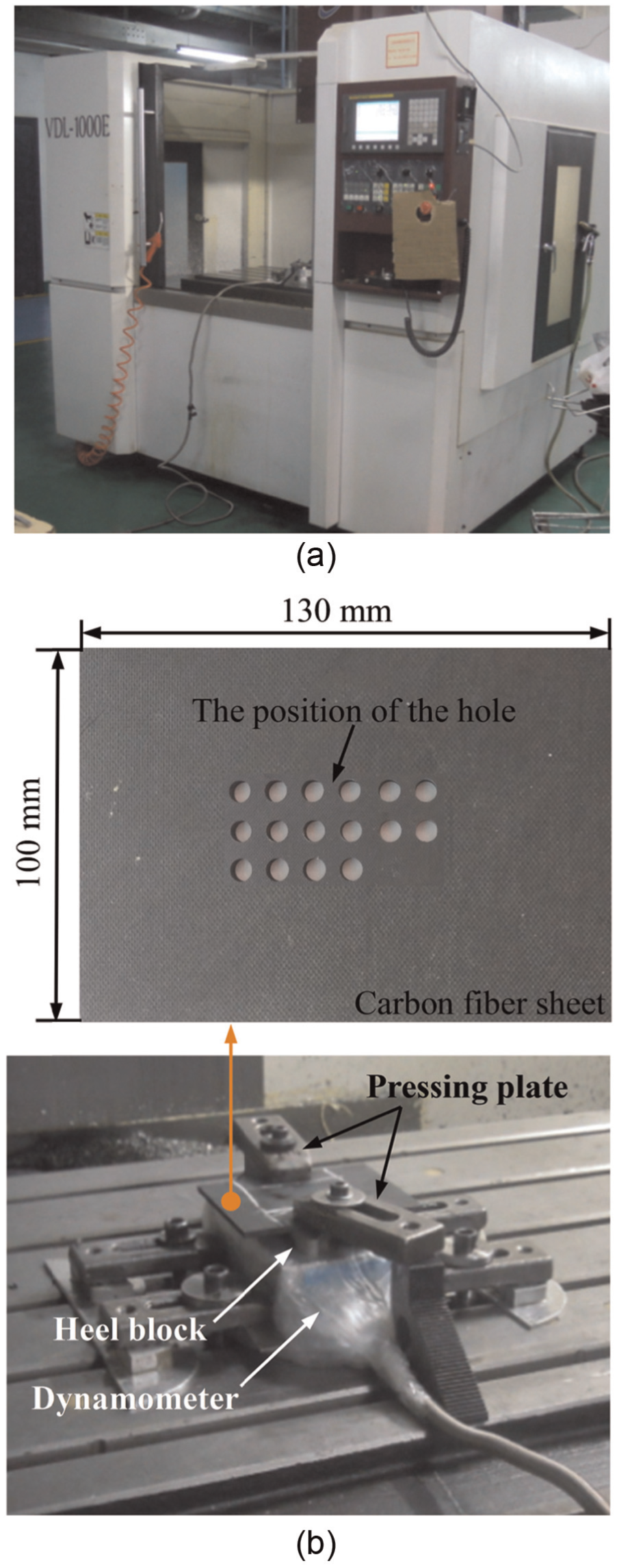
Drilling experiment system: (a) CNC milling machine VDL-1000E and (b) the clamping workpiece and test device.
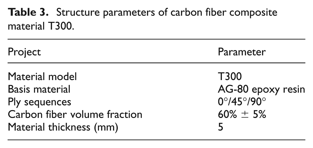
An 8-mm polycrystalline diamond (PCD) drill was used in the experiments, and its geometric parameters are shown in Table 1. The workpiece is aircraft material T300. Structural parameters of the workpiece material are shown in Table 3.
Structure parameters of carbon fiber composite material T300.
Experimental result
As displayed in Figure 5, when the spindle speed was 3000 r/min and the feed speed was 210 mm/min, the average axial force measured in the experiment (Ave.exp) was 151.4 N, which represents a 7.4% deviation as compared to the simulation result. Moreover, under different cutting parameters, the variation regularity of the simulated results was almost the same as that of the experimental results with similar values.
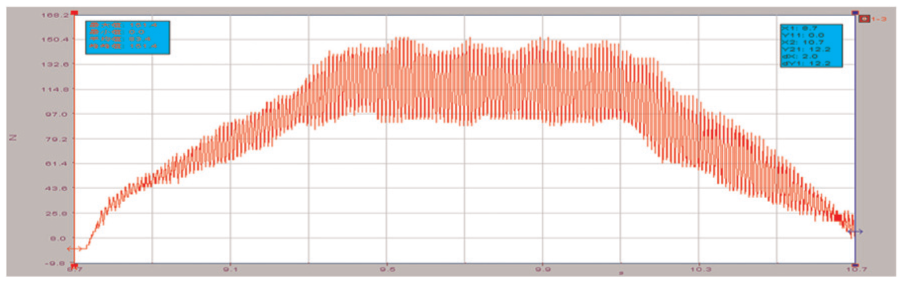
The curves of axial force.
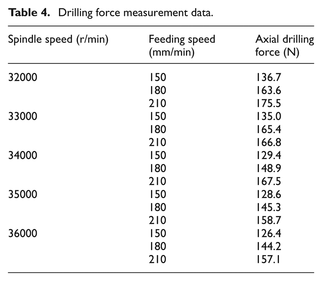
Under different cutting parameters of drilling experiments using PCD drill, the cutting force is shown in Table 4.
Drilling force measurement data.
The establishment of the cutting force regression model
Table 4 displays the axial force values measured during the drilling of a carbon fiber composite material using a PCD insert under different cutting parameters. A multi-element nonlinear data analysis model was adopted by setting the feeding speed vf and spindle speed n as independent variables of the dualistic-quadric regression equation (equation (1))
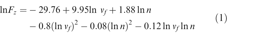
The mean square error is 0.03. Equation (1) can be transformed into an empirical equation of the axial force during the drilling of a carbon fiber composite material using a PCD insert (equation (2))
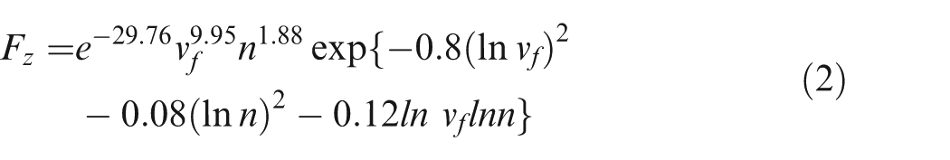
The holding conditions of equations (1) and (2) were as follows: the spindle speed was 1000 r/min ⩽n⩽ 7000 r/min (i.e. 6.91 ⩽ ln n⩽ 8.85), and the feeding speed was 140 mm/min ⩽vf⩽ 220 mm/min (i.e. 4.94 ⩽ lnvf⩽ 5.39).
The surface diagram displayed in Figure 6 was plotted based on equation (1), which was the logarithmic relationship between the spindle speed, feeding speed, and axial force.
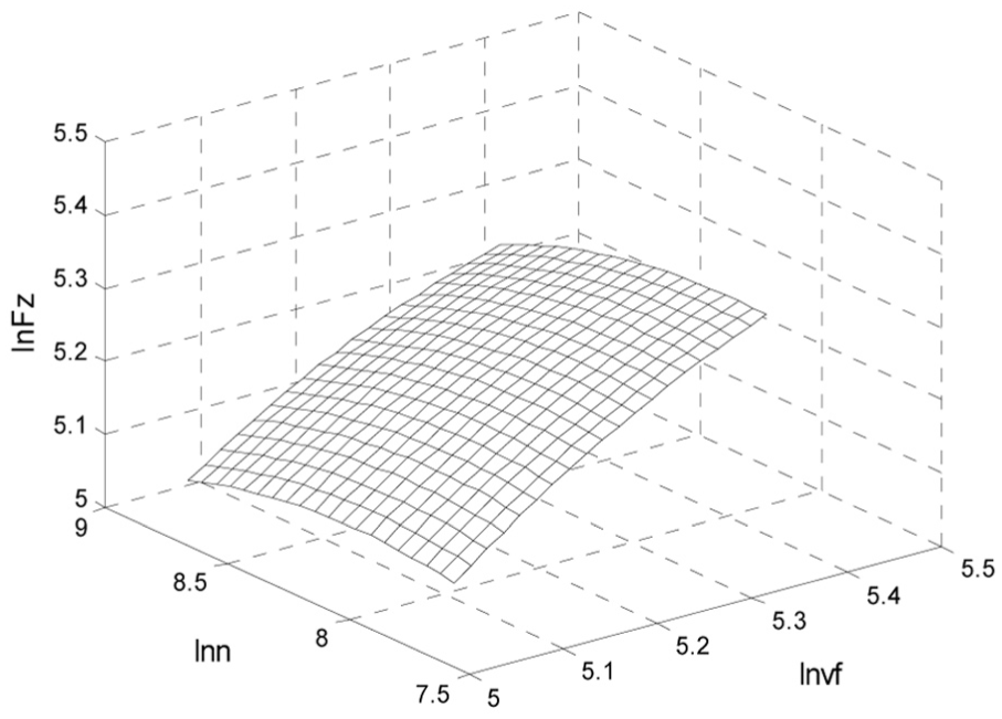
The relationship surface curve of lnn, lnvf, and lnFz.
To further characterize the influence of vf on Fz, the univariate function between lnFZ and lnvf was calculated based on equation (1) as well as the specific values of the spindle speed:
When the spindle speed is 2000 r/min

When the spindle speed is 3000 r/min

When the spindle speed is 4000 r/min

When the spindle speed is 5000 r/min

When the spindle speed is 6000 r/min

Figure 7 shows the curves corresponding to equations (3)–(7). When the process parameters were within the range of 6.91 ⩽ ln n⩽ 8.85 and 4.94 ⩽lnvf⩽ 5.39 and the spindle speed was fixed, lnFz increased as lnvf increased. That is, the axial force increased as the feeding speed was improved with a nearly linear tendency. Moreover, the slopes of all curves were close to each other.
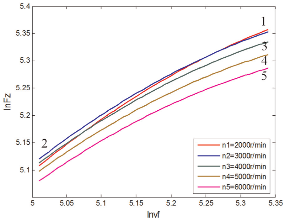
The relationship curve of lnFz and lnvf under different n values.
Similarly, to further reveal the influence of n on Fz, the relationship between lnFz and lnn was expressed by selecting specific feeding speed and equation (1) is as follows:
When vf = 150 mm/min

When vf = 180 mm/min

When vf = 210 mm/min

Figure 8 shows the curves corresponding to equations (8)–(10), which are logarithmic relationships between the axial force and the spindle speed under different feeding speeds:
Under the same feeding speed vf condition, when lnn increased, the value of lnFz first increased to the maximum value and then reduced. That is, the axial force Fz presented a tendency of first-increase-then-decrease as the spindle speed n increased.
When lnFz reached its peak value, lnn was defined as lnn-man, which can be expressed as a function of the feeding speed vf, that is, lnn-man = lnn-max(vf). Thus, it is implied that when Fz reached its maximum value, the spindle speed n decreased as vf increased.
The maximum value of lnFz was set as lnFz-max, which was also a function of the feeding speed vf and can be expressed as lnFz-max = lnFz-max(vf). Additionally, lnFz-max increased as vf improved. Similarly, the maximum axial force Fz increased as the feeding speed vf improved.
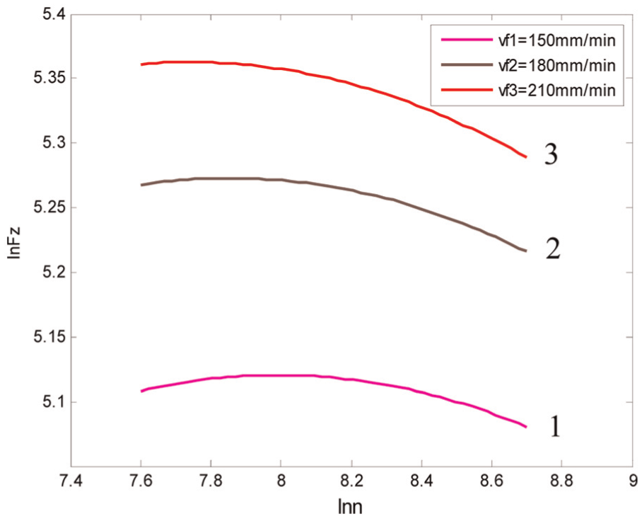
The relationship curve of lnFz and lnn under different vf values.
Conclusion
The drilling simulations and experiments of carbon fiber composite material were conducted; then, the change rules of the axial cutting force were analyzed; and the regression model of axial cutting force was established. According to the simulation and experimental results, the simulation results were fit to the actual. Therefore, simulation could be used instead of a part of the experiments so as to reduce the workload and cost of the experiments.
When the spindle speed was increased from 2000 to 6000 r/min, the axial cutting force represented a 10% reduction. The increase in the feed rate caused obvious increase in axial force. The axial force of according cutting parameters could be forecasted using the regression model. These could be used as the basis for the optimization of cutting parameters.
Based on the influence rule of cutting parameters on the axial cutting force, drilled-hole quality, hole exit burr, and the internal delamination of carbon fiber composite materials during drilling can be further studied. Therefore, the research results can provide a foundation for the investigation of the improvement of the machining precision and quality during drilling carbon fiber composite materials.
Footnotes
Declaration of conflicting interests
The author(s) declared no potential conflicts of interest with respect to the research, authorship, and/or publication of this article.
Funding
The author(s) disclosed receipt of the following financial support for the research, authorship, and/or publication of this article: This research is supported by the Aerospace with carbon fiber composite materials research and development of high-efficient cutting technology and cutter cooperation (2014DFA70400).