
Abstract
With the ever-increasing demands on miniaturization, the requirement on good forming quality and high-dimensional accuracy of micro-parts is dramatically motivated. As a decisive factor affecting the accuracy of micro-bent parts, the springback is significantly influenced by size effects. In order to explore size-effect-associated springback behaviour and evaluate the forming quality of micro-bent parts, an experimentally based investigation on the influence of foil thickness, grain size and their interactive effect on the springback behaviour of CuZn37 brass foils with different thicknesses and grain sizes was carried out. The experimental results obtained via micro-tensile tests revealed that the yield strength, Young’s modulus and elongation had a close correlation with the thickness-to-average-grain-size ratio. A micro W-bending process was used to perform the bending tests. Both springback and negative springback phenomena were observed. It was found that how size effects may influence the amount of springback would depend on the springback behaviours, for example, positive springback or negative springback. In addition, scatter phenomenon of the springback behaviour was analysed quantitatively. An increased scatter was observed for the 50-µm-thick specimens when the thickness to average grain size decreased, whereas an inverse tendency of the decreased scatter of the negative springback was found for the 75- and 100-µm-thick specimens with the increase in the grain size. Finally, forming quality of the W-shaped micro-bent parts was assessed.
Introduction
Micro-forming, acknowledged as the most promising manufacturing technology, offers attractive characteristics to fabricate low-cost and high-quality micro-parts efficiently. 1 With the increasing trend of miniaturization, the growing demand on the dimensional accuracy of micro-parts renders great challenges and thus stimulates investigation on the precision evaluation of micro-formed parts. In terms of the micro-bending process, the springback, caused by elastic recovery during unloading, is an important factor significantly affecting the dimensional accuracy of micro-bent parts. Especially when the geometrical dimension of micro-bent parts is downscaled to micro-scale, the advent of size effect hinders the direct application of macro-scaled bending theory to the micro-scale. 2 In addition, the existing tolerance standards and precision evaluation methods seem not suitable for micro-formed parts because some material-related parameters, such as grain size and grain orientation, which have not been taken into consideration in the macro-scale bending process, start to pose a significant impact on the mechanical properties of the material and further affect the dimensional accuracy of micro-bent parts. Therefore, in order to establish a quantitative model to evaluate the dimensional accuracy of micro-bent parts, the comprehensive understanding of relevant size effects and their influences on the micro-bending process has become the primary task.
Geiger et al. 3 extensively reviewed the state of the art of various micro-forming technologies, and their latest development was updated by Fu and Chan. 4 Vollertsen and colleagues5,6 presented a systematic review on the definitions and categories of size effects and shed light on their potential use in the manufacturing of metallic components. Diehl et al. 7 comprehensively investigated the influence of the material microstructure on the mechanical properties of SE-Cu 58 and Al metal foils by tensile tests, hydraulic bulge tests and bending tests. Raulea et al. 8 carried out tensile and bending tests of aluminium sheets and revealed that the yield strength decreases with the decrease in specimen thickness at a constant grain size. However, the investigation conducted by Suzuki et al. 9 demonstrated the opposite tendency of the influence of the yield strength in tensile tests, presenting a clear increase in the yield strength with the reduction in the thickness when the average grain size remained constant. Guo et al. 10 discovered both the foregoing tendencies of the influence of foil thickness on the yield strength in tensile tests. Gau et al. 11 studied how size effects affected the flow stress and formability and pointed out that it can be expressed as functions of the t/d (thickness-to-average-grain-size) ratio. Liu et al. 12 investigated the effect of thickness and grain size via tensile tests and three-point bending tests. Wang et al. 13 developed a constitutive model considering the influence of grain size, thickness, t/d ratio and surface property when there is one or several grains in the thickness direction of the thin sheet metal. Fang et al. 14 demonstrated the different influence of the t/d ratio on the mechanical properties and fracture mechanism when the t/d ratio was larger than, less than and equal to unity.
In order to investigate the influence of size effects on the springback behaviour, various bending processes have been employed. Three-point bending was utilized by Gau et al. 15 to study the springback behaviour. They found that the well-established concept of springback is not applicable when the material thickness is less than 350 µm. Similar bending processes were also adopted by Liu et al. 12 and Wang et al. 16 Diehl et al. 17 conducted free-bending tests and observed that the springback angle increases with the decrease in the foil thickness and decreases with increasing average grain size. Li et al. 18 further proposed a constitutive model based on both plastic-strain and plastic-strain-gradient hardening to analyse the springback angle via a similar free-bending process adopted by Diehl et al. 17 Wang et al. 19 carried out micro U-bending to assess the influence of size effects on the mechanical properties and springback behaviour. Lajarin and Marcondes 20 adopted the U-bending test to study the influences of process and tool parameters on the springback. Choudhury and Ghomi 21 investigated the influences of 11 factors on springback in V-bending dies. Fang et al. 22 proposed a new finite element (FE) model based on the consideration of Voronoi tessellation and grain heterogeneity to simulate the micro V-bending process. In addition, Chen and Jiang 23 also conducted similar micro V-bending tests to study the influence of grain size effect on the springback behaviour and the punch radius effect was examined as well. 24 A roll-bend forming device and a pressure-sizing process were developed by Ma et al. 25 to investigate the influence of grain size on the springback behaviour. The experimental results revealed that the springback behaviour is closely associated with the t/d ratio and crystallographic texture.
From the available literature, it is indicated that foil thickness, grain size and the t/d ratio do have considerable influences on the springback behaviour. However, most of the researches investigated so far have dealt only with conventional bending processes, such as three-point bending, free-bending, U-bending and V-bending, and the micro-bending addressed in this study which produces multi-curvatures renders different characteristics in terms of bending and springback. In the micro W-bending experiment reported in this article, occurrence of both, springback and negative springback behaviours, were observed. Although the negative springback phenomenon in the bending process has been theoretically interpreted by the finite element method (FEM) 26 and also been explored by the combination of experiments and the FEM simulation,27–29 most of the studies were conducted on the macro-scaled V-bending processes 30 with the bending specimens thicker than 100 µm. Furthermore, as an essential aspect of the springback behaviour, the scatter of the springback amount was merely qualitatively described. A study conducted by Liu et al. 12 showed that both grain orientation and sheet thickness have significant influences on the scatter of the springback amount. A greater scatter of the springback angle was also observed by Diehl et al. 7 when the grain size increased. To date, no quantitative analysis of the springback scatter has been reported.
Therefore, regarding the abovementioned considerations, the main objective of this research was to carry out an experimentally based investigation on the influence of size effects on the springback behaviour in micro W-bending, including quantitative description of the scatter of springback. The results from this investigation are expected to be used as a reference for further studying springback in complex micro-bending as well as considering factor of scatter in dimensional control in micro-forming of sheet metals.
Materials and methods
Material and specimen preparation
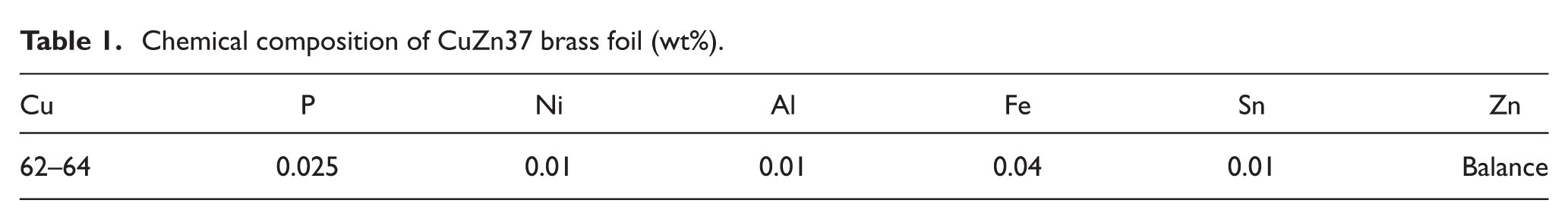
Brass was chosen as the experimental material due to its good mechanical properties, excellent forming performance and electrical conductivity, meeting the increasing requirement of the miniaturization of electronic components. In this research, CuZn37 brass foils from cold rolling with thickness of 25, 50, 75 and 100 µm were used. The chemical composition is shown in Table 1.
Chemical composition of CuZn37 brass foil (wt%).
The length and width of the specimens are 16 and 12 mm, respectively, prepared via MAXIEM 1515 waterjet machining. The bending axis is parallel to the rolling direction of the specimens. In order to eliminate the effects of rolling texture and obtain various grain sizes, the specimens were annealed at temperatures ranging from 450 °C to 650 °C with different holding time in the 90% N2+ 10% H2 protection condition before furnace cooling to room temperature. The microstructures of the brass foils were observed by optical microscope after having been etched with a solution of 5 g FeCl3, 10 mL HCl and 100 mL H2O for 15–20 s. Figures 1 and 2 present the microstructures of specimens along the foil plane and in the thickness direction, respectively, which were annealed under the condition of 650 °C with 1-h holding time.
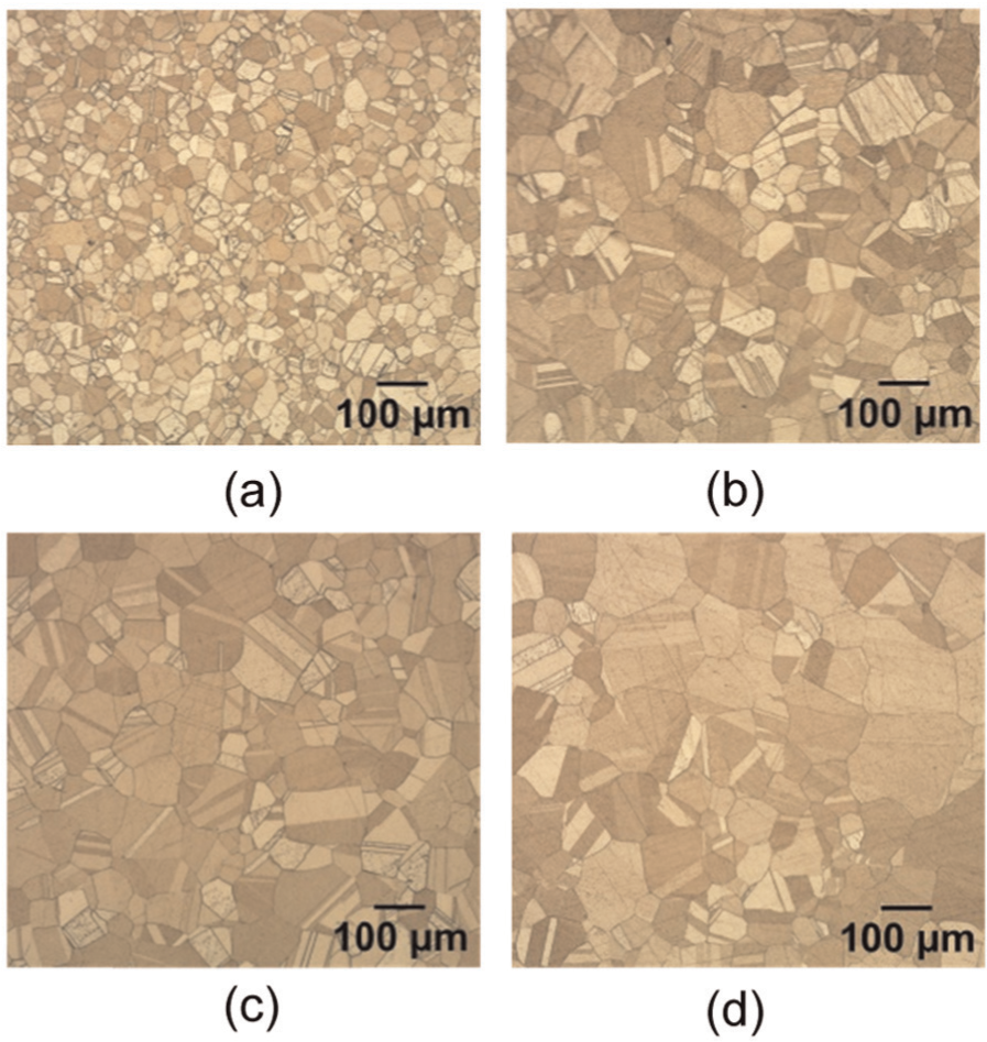
Microstructures of specimens along the foil plane, which were annealed at 650 °C with 1-h holding time: (a) t = 25 µm, d = 37.3 µm; (b) t = 50 µm, d = 69.5 µm; (c) t = 75 µm; d = 82.8 µm; and (d) t = 100 µm, d = 98.2 µm.
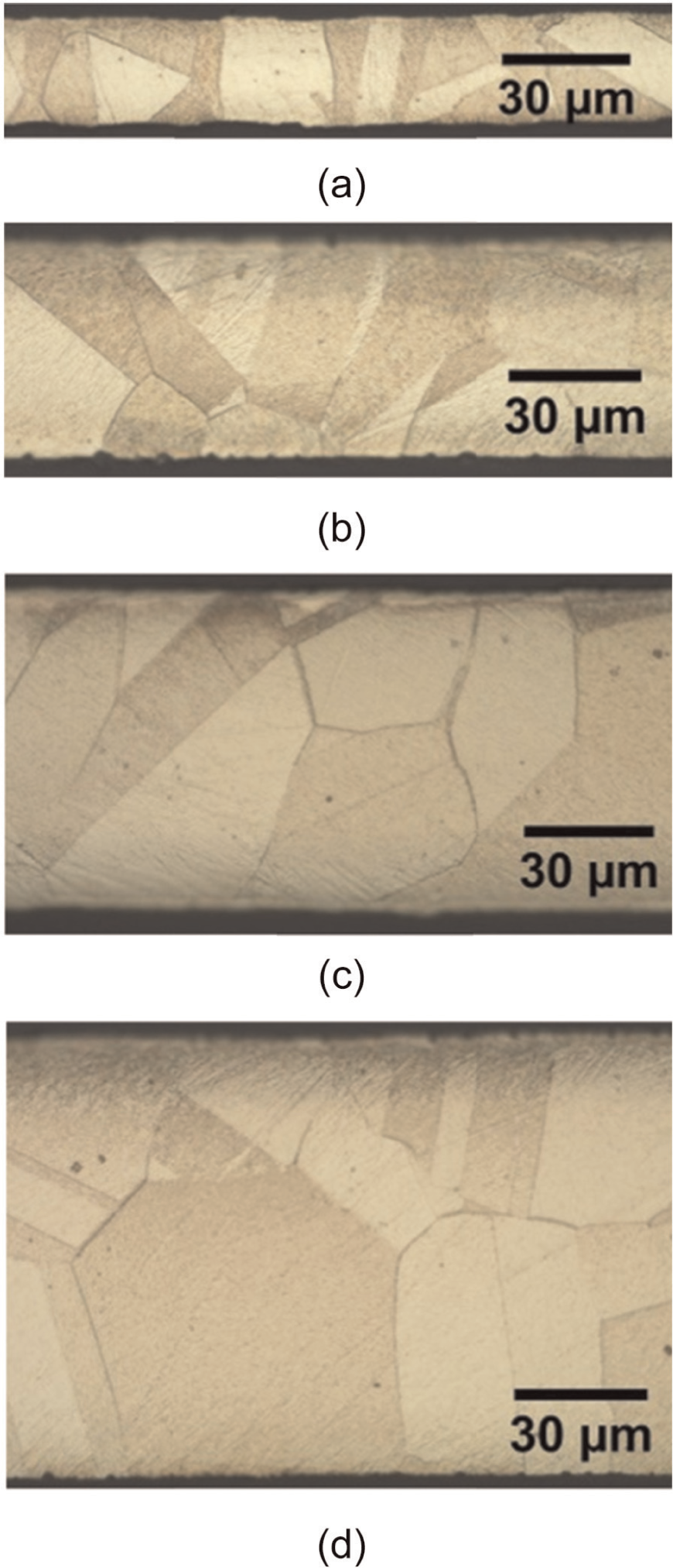
Microstructures of specimens in the thickness direction, which were annealed at 650 °C with 1-h holding time: (a) t = 25 µm, d = 37.3 µm; (b) t = 50 µm, d = 69.5 µm; (c) t = 75 µm, d = 82.8 µm; and (d) t = 100 µm, d = 98.2 µm.
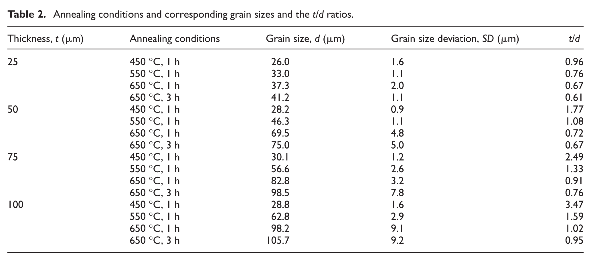
The linear intercept approach based on ASTM E112 standard was adopted to measure the average grain size. With a view to obtaining the precise grain size, images of six widely separated sections in each metallographic image were captured to calculate the average grain size. The average grain sizes and the t/d ratios under corresponding annealing conditions are listed in Table 2.
Annealing conditions and corresponding grain sizes and the t/d ratios.
Micro-tensile test
An Instron 5969 universal testing instrument was utilized to carry out micro-tensile tests at room temperature. The tensile specimen depicted in Figure 3 was sectioned according to ASTM E8 standard before the annealing treatment. Therefore, machining stress during the cutting could be avoided in such thin foils. A low strain rate of 0.01 mm/min was used for all the specimens to prevent the strain rate effect on the deformation behaviour of the CuZn37 brass foils. In order to evaluate the scatter of the mechanical properties, five tensile tests were conducted for every combination of foil thickness and grain size.
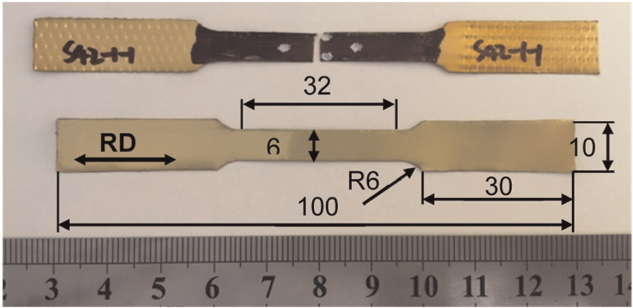
The tensile test specimen.
Micro W-bending
W-shaped micro-clips are used to mount the fibre Bragg grating on the tendon of the object to measure the change in strain or temperature, which have been widely employed in the optical communication or sensing systems. Furthermore, they also have potential applications in electronics, vehicles, aircraft and medical devices. In order to fabricate this kind of clips, a W-shaped forming tool was designed, as shown in Figure 4(a). The bending angle is 80° for both punch and die. The depth and width of the W-groove die are 4.5 and 9 mm, respectively. Considering the forming feasibility, the tip radii on the W-shaped punch and die are marginally different. The W-groove on the die (Rd) has two different radii: 0.35 mm for the middle radius and 0.15 mm for the radii on both sides, whereas the tip radii on the punch (Rp) are 0.4 and 0.1 mm, respectively.
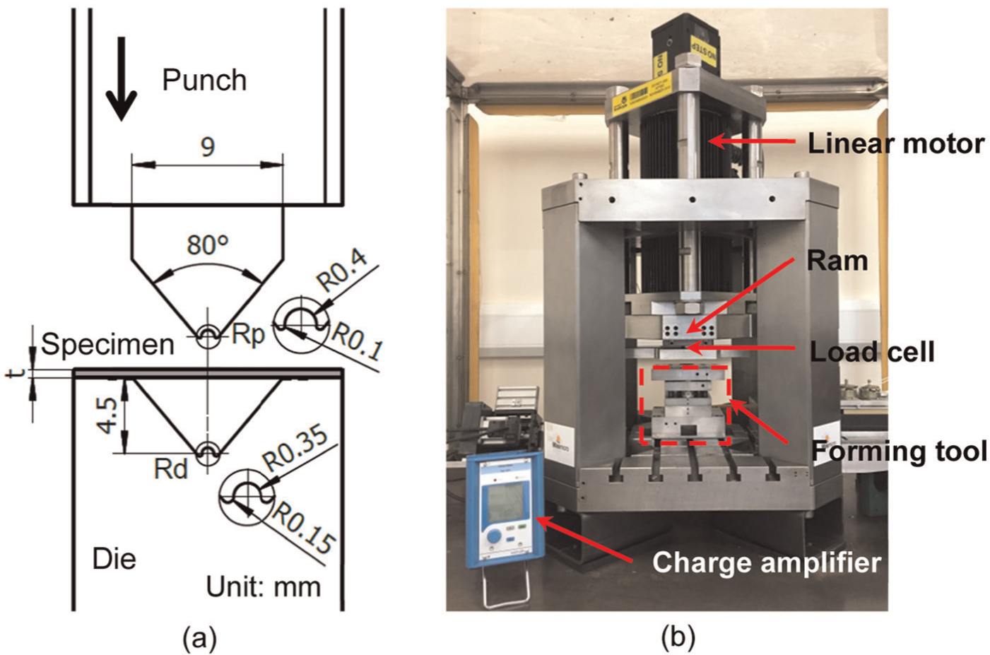
Schematic illustrations of (a) W-shaped punch and die and (b) micro-sheet-forming machine.
Micro W-bending process was carried out on a bench-top micro-sheet-forming machine, equipped with the abovementioned W-shaped forming tool. As shown in Figure 4(b), the machine ram is driven by a linear motor. The maximum force of the machine is 5.3 kN. Additionally, a load cell with a measurement resolution of 0.1 N and a positional encoder providing the 0.1-µm vertical-position resolution are integrated into the machine. 31 During the bending process, a KISTLER charge amplifier (Type 5015A) was used to monitor the punch force indicating problems in the process. Due to the innovative modular design of the machine, it has a flexible setup, enabling the integration of versatile forming tools to fabricate different micro-sheet-metal parts with the thickness ranging from 20 to 100 µm.
Micro W-bending process is accomplished by two stages: loading and unloading. In the loading stage, the machine ram moves down to press the upper plate of the forming tool, making the punch initiate a downward movement to force the specimen into the die gradually until the punch stroke reaches to a set value. In the unloading stage, the load is released after the punch moves up, and hence the material undergoes a process of elastic recovery causing the final bent angle to open slightly, which is called springback. However, in some circumstances, it may be smaller than the desired bent angle, which is considered as negative springback. 32
In order to investigate the influence of grain sizes and foil thicknesses on the springback behaviour in the micro W-bending process, experiments were conducted at room temperature with constant punch frequency (0.25 Hz) for all the bending specimens. The clearance between the W-shaped punch and die was adjusted according to the four different thicknesses. No lubricant was used between the surfaces of the specimen, W-shaped punch and die. For each kind of the specimen, six bending tests were performed to evaluate the scatter of the experimental error. Subsequently, the bent angles were measured using Mitutoyo Quick Scope, a vision-measuring microscope offering high-speed non-contact precision measurement, which is highly suited for the present measurement. In order to increase the measurement accuracy, each bent specimen was measured three times and the results were then averaged.
Results and discussions
Size effects on material properties
The relationship between the true stress and true strain with different grain sizes for the specimens of 25 µm thickness is shown in Figure 5(a). It is found that larger grain size induces larger elongation but sharply decreased yield strength when the foil thickness remains constant. Moreover, a slightly lesser Young’s modulus was observed in the enlarged region shown in Figure 5(a) when the grain size grew larger. The decrease in yield strength can be explained by the Hall–Petch relation, which represents the larger the grain size, the lower the material strength. 10 Another reason contributing to this effect is that the surface grains have lesser constraints compared to the inner ones, thus they present relatively lower flow stress. For a given foil thickness, the proportion of surface grains increases when the average grain size grows larger, leading to the decrease in the flow stress.
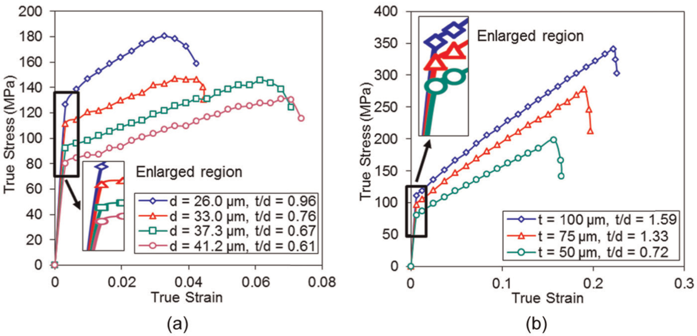
Size effects on material properties: (a) 25 µm specimens with different grain sizes and (b) different thicknesses with a similar grain size d = 56.6–69.5 µm.
Figure 5(b) illustrates the effect of foil thickness on the stress–strain curves for the specimens with the similar grain size. It is observed that the yield strength and elongation gradually decrease with decreasing foil thickness while Young’s modulus experiences a minor decline, as presented in the enlarged region in Figure 5(b). When there are several grains in the thickness direction, the yield strength is strongly influenced by the surface grain weakening effect, illustrating how the material strength decreases with the decrease in foil thickness.
As for the interactive specimen geometrical effect and grain size effect on the mechanical properties of the brass foils, the yield strength is observed to decrease with decreasing t/d ratio in Figure 5(a) and (b). Consequently, the brass foils used in the research have demonstrated both the grain size effect and the specimen geometrical size effect, indicating the feasibility of employing this material to study the size effects on the springback behaviour in the micro W-bending process.
Effect of grain size on springback behaviour
Figure 6 presents the effect of grain size on the springback behaviour. The springback amount decreases gradually with increasing grain size for all the specimens of 25 µm thickness. This is in agreement with the experimental results obtained by Wang et al. 16 and Diehl et al. 17 For 50-µm specimens, a similar tendency is found when the specimens were annealed from 450 °C to 550 °C, whereas the final bent angle turns out to be slightly smaller than the desired one when the grain size grows larger. The 75-µm specimen with the grain size of 30.1 µm shows a practically ideal bent angle (80.001°). Afterwards, the springback angle is found to be less than 0°, indicating that the final bent angle is smaller than the desired 80°, which is called negative springback. The exhibited negative springback increases moderately with the increase in grain size. Regarding the 100-µm specimens, all the heat-treated specimens exhibit the trend of the increased amount of negative springback under larger grains. Similarly, this reversed springback phenomenon was also reported in the research conducted by Chen and Jiang. 23
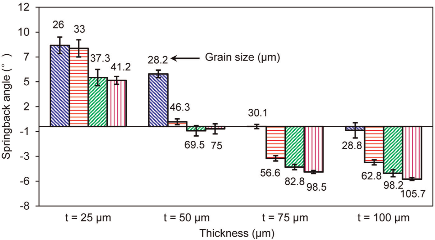
Influence of grain size on springback angle.
Effect of foil thickness on springback behaviour
The influence of different foil thicknesses with the similar grain size on the springback angle is demonstrated in Figure 7. The data presented in Figure 7 were a mean value of the six bent parts repeatedly formed under the same conditions. It is apparent that the specimens with the grain size varying from 26 to 30.1 µm experience an increased springback (from 0.001° to 8.173°) when the foil thickness is reduced from 75 to 25 µm, which is in accordance with the traditional bending theory in the macro-scale. When the grain grows twice larger than that in the foregoing experiment, a similar tendency occurs, comparing to the lines illustrated in Figure 7. However, the specimens with the grain size of 56.6–69.5 µm present an obvious decrease in negative springback amount (from 3.609° to 0.419°) with the decrease in the thickness. It shows that foil thickness has different effects on the springback and negative springback. In such a circumstance, the conclusion on springback drawn from a conventional bending process may not be applicable.
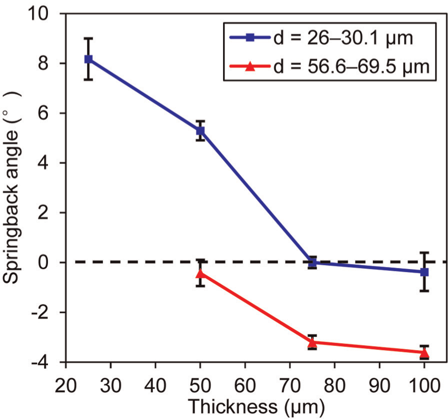
Influence of foil thickness on springback angle.
Compared to the micro W-bending process addressed in this study, a V-bending process may generate one radius, while the W-shaped bending generates three. Mutual influences among the individual radius on springback determine final geometry of the formed part. This represents a typical case for studying mutual influences in a complex micro-forming process where bending, reverse bending, rebending and so on, are combined in a neighbouring area/section. As a consequence, the analyses of size effects and springback are much more complex than that for a simple bending process.
Effect of t/d ratio on springback behaviour
Figure 8 describes the influence of t/d on the springback behaviour under the premise of the same thickness. To be more specific, the springback amount dramatically decreases within a limited range of t/d for the specimens of 25 and 50 µm. Nevertheless, for 75- and 100-µm specimens, with the decrease in t/d, the negative springback occurs and its amount increases gradually.
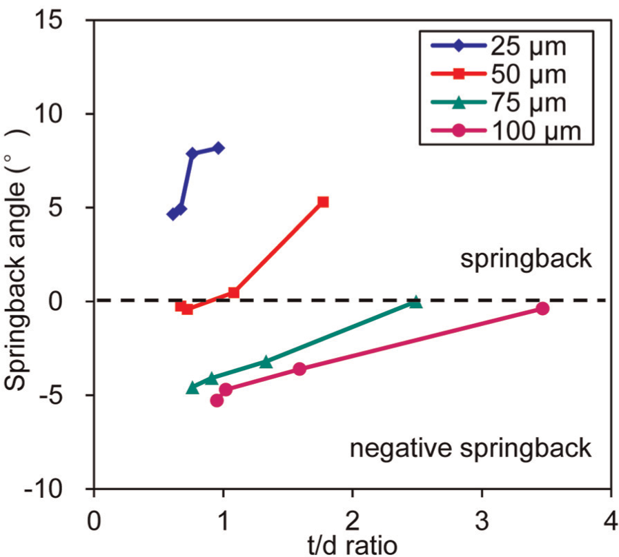
Influence of t/d on springback angle.
As the experimental results demonstrated, the t/d ratio for the occurrence of negative springback is 0.72, 1.33 and 3.47 for 50, 75 and 100 µm, respectively, whereas no negative springback is found for the thickness of 25 µm. It is revealed that no identical t/d ratio is applicable for different foil thicknesses to distinguish the springback and negative springback behaviours in the micro W-bending process. In addition, the t/d ratio classifying these two springback behaviours are different compared to the results obtained by Chen and Jiang, 23 which states that the negative springback occurs when the t/d ratio is 1.2. Therefore, it is indicated that the occurrences of different springback behaviours depend on the process and material properties such as thickness and grain size, which need further investigation to elaborate on this issue.
Scatter of springback behaviour
In order to comprehensively investigate the springback and negative springback behaviours in the micro W-bending process, the scatter, signifying the distribution of the amount of springback or negative springback, was also explored. The experimental results are listed in Table 3.
Scatter of the springback and negative springback amount (in degrees).
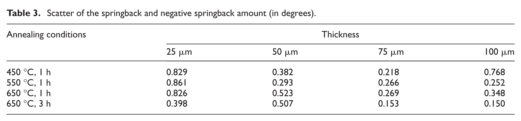
A slightly increased scatter is observed for the 50-µm specimens, when the grain size grows from 28.2 to 75 µm and t/d decreases from 1.77 to 0.67, respectively. Additionally, the specimens with the similar grain size of 56.6–69.5 µm, as shown in Figure 7, undergo a monotonically increased scatter of the negative springback amount (from 0.252 to 0.523) when the foil thickness decreases from 100 to 50 µm, and the t/d ratio decreases from 1.59 to 0.72, respectively. The reason for the increased scatter of the springback and negative springback amount is that for the specimens with increasing grain size when the foil thickness remains constant or decreasing specimen thickness when the grain sizes are similar, there will be only a few grains or even less than one grain in the thickness direction of the foils. This weakens or eliminates the even distribution of different grains with different shapes, sizes and orientations, contributing to the significant anisotropic properties of each grain in the deformation behaviour. Therefore, the grains presenting inhomogeneous properties will result in the scatter of the material properties, which further affects the dimensional accuracy of micro-bent parts.
However, a different variation trend is observed in the 75- and 100-µm specimens with different grain sizes depicted in Figure 6. With the t/d ratio of 75-µm specimens decreasing from 2.49 to 0.76, the scatter of the negative springback amount decreases slightly from 0.218 to 0.153, while a significant decline of the negative springback scatter (from 0.768 to 0.150) is presented in 100-µm specimens when the t/d decreases from 3.47 to 0.95. A possible explanation could be some other factors besides the t/d, such as the mechanism of the springback and negative springback need to be taken into account to investigate the scatter phenomenon, thus indicating the necessity of an in-depth study on the negative springback behaviour of the W-shaped micro-bent parts. Another reason is most likely to be the small number of bending specimens, which is not sufficient to investigate the scatter phenomenon of the negative springback behaviour.
Quality of the W-bent parts
With the increasing requirements of practical application, how to control the dimensional accuracy and the forming quality of the W-shaped micro-bent parts has become an indispensable issue during the feasibility study of the micro W-bending process. Figure 9 shows the measurement results of bent parts which were previously annealed below 650 °C with 3-h holding time.
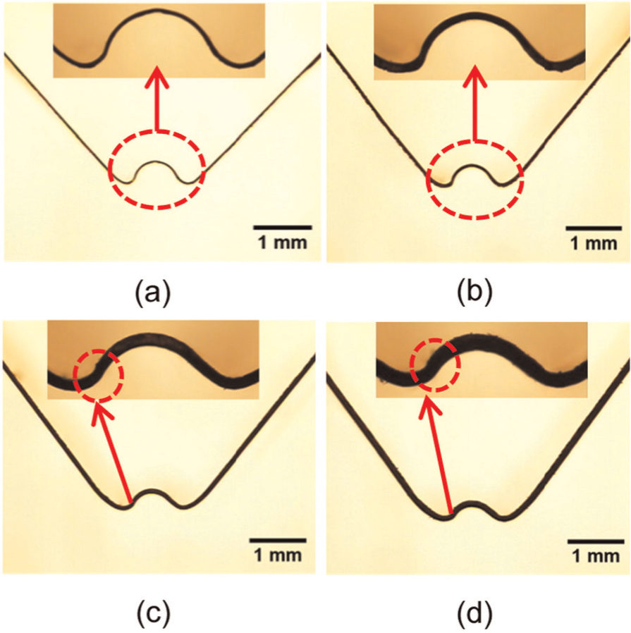
W-shaped micro-bent parts annealed below 650 °C with 3-h holding time: (a) t = 25 µm, bending angle = 84.253°; (b) t = 50 µm, bending angle = 80.343°; (c) t = 75 µm, bending angle = 75.339°; and (d) t = 100 µm, bending angle = 75.056°.
From Figure 9, it can be observed that the bent angle decreases from 84.253° to 80.343° when the thickness increases from 25 to 50 µm. Afterwards, with increasing thickness, the springback turns to negative springback (75.339° for 75-µm thickness) and the negative springback increases from 4.661° to 4.994° when the foil thickness increases from 75 to 100 µm.
With respect to the bending quality, the occurrence of a minor thinning is noted around the bending area for 75- and 100-µm parts, as shown in Figure 9. This is possibly attributable to that this area is the first contact location when the punch presses the part and thus it experiences a small amount of stretching of the material during the bending process, which will be verified in the further study of the process simulation. In view that thinning precedes local necking and then results in cracking, to this end, the process parameters, such as punch stroke, punch frequency and punch force, should be controlled and optimized to avoid the thinning and ensure the dimensional accuracy and the forming quality of the W-shaped micro-bent parts in the further work.
Conclusion
W-bending was used to investigate the influences of grain size, foil thickness and t/d ratio on the springback and negative springback behaviours in a complex bending process. CuZn37 brass foils were used as the material for study. The following conclusions may be drawn from the research conducted so far:
The foil thickness, grain size and t/d ratio significantly influence the yield strength and elongation of the brass foils, while Young’s modulus is slightly influenced by these size effects. It is revealed that yield strength decreases with decreasing t/d ratio.
Both springback and negative springback are observed in the micro W-bending. As far as the influence of the foil thickness is concerned when the grain size is small, the springback increases with the decrease in the foil thickness when the grain sizes range from 26 to 30.1 µm, whereas the negative springback amount decreases with the decrease in the thickness when the grain sizes range from 56.6 to 69.5 µm.
It is found that the springback decreases with decreased t/d ratio for the specimens of 25 and 50 µm in thickness. Whereas, for 75- and 100-µm-thick specimens, the negative springback amount increases when the t/d ratio decreases. In addition, no identical t/d ratio is found to be able to indicate the occurrence of the negative springback for different foil thicknesses.
A monotonically increased scatter of the negative springback is observed as the t/d ratio decreases when the grain size is similar, while an inverse trend of the negative springback scatter occurs for 75- and 100-µm-thick specimens, with increase in the grain size.
W-shaped bending is an ideal model for studying mutual influences when several bends occur in a neighbouring area/section, which helps to develop understanding of forming of complex-shaped micro-sheet-metal components.
Although the influences of size effects on the quality of micro-formed parts have drawn attention of the research broadly, still, more investigations need to be carried out in order to establish quantitative descriptions of these influences, especially for more complex forming-processes and by considering scattering factors existing in materials and processes.
Footnotes
Acknowledgements
The authors also would like to express their gratefulness to the Emeritus Professor Frank Travis, The University of Strathclyde, for the proofreading of the manuscript.
Declaration of conflicting interests
The author(s) declared no potential conflicts of interest with respect to the research, authorship and/or publication of this article.
Funding
The author(s) disclosed receipt of the following financial support for the research, authorship, and/or publication of this article: This work was supported by the Specialized Research Fund for the Doctoral Program of Higher Education of China (no. 20110181110084) and the sponsorship provided by the University of Strathclyde for conducting joint research in micro-forming with Sichuan University.