
Abstract
Blasting erosion arc machining (BEAM) is adopted to improve the machining efficiency of high fraction (50 vol.%) SiC/Al matrix composites. Results of the fractional factorial experiments and full factorial experiments indicate that the electrical parameters (peak current, pulse duration and pulse interval) are the main impact factors of the machining efficiency, and when the peak current is 500 A, the pulse duration is 8 ms and the pulse interval is 2 ms, the material removal rate reaches to 6000
Introduction
SiC/Al matrix composites are widely used in aerospace, energy and biology industries because of their improved strength, modulus, wear and fatigue resistance. 1 The difference of reinforced SiC particle fractions in the matrix material (alumium) make the composites present different characteristics. For example, the Young’s modulus increases with increasing SiC volume fraction, 2 and the coefficient of thermal expansion decreases linearly with the particle volume fraction. 3 Machining performances of different fraction SiC/Al matrix composites are also not the same. Generally, the processing performance reduces with an increasing fraction of SiC particles. At present, industrial usage of SiC/Al matrix composites is mainly focused on the low fraction (e.g. 20 vol.% ) composites. Applications of the high fraction (e.g. 50 vol.% ) SiC/Al matrix composites are limited because of their limited machining efficiency and high processing costs.
When adopting a traditional cutting system for the processing of SiC/Al matrix composites, the main problem is the contradiction between the machining efficiency and tool life. For instance, Bhushan et al. studied the turning of a 15 wt.% SiC (about 12–15 vol.%) workpiece,
4
and found that the maximum material removal rate (MRR) was about 17,300
Non-traditional machining, such as electric discharge machining (EDM), wire electrical discharge machining (WEDM) and electrochemical machining (ECM) can also be used for the machining of SiC/Al composites. However, the machining efficiency of non-traditional machining is also very limited. For instance, Mohan et al. employed a tubular electrode to machine 20 vol.% SiC/Al matrix composites with EDM,
7
the maximum MRR was only about 60
Compared with conventional EDM, the electrical arcing process has a higher energy density which can result in a higher material removal rate. Wang et al. proposed a compound machining of electrical arc machining and electrical discharge milling for the processing of titanium alloys, AISI H13 and GH 4169.9–11 Yuan et al. and Trimmer et al. reported a high-speed electro-erosion milling (HSEM),12,13 which can be used for the machining of nickel-based alloys. Ye et al. developed a high-efficiency electrical discharge milling which was utilized to machine Inconel 718. 14 Guo proposed high efficiency milling EDM which could also be used to machine titanium alloys. 15
Blasting erosion arc machining (BEAM) is also a kind of arc machining which was proposed in recent years. It has been demonstrated that BEAM can be used for the machining of several difficult to cut materials with high efficiency. 16 Xu et al. studied the influence of flushing holes on the machining performance of BEAM and machined nickel-based alloy with positive polarity BEAM utilizing a bundled electrode.17,18 Chen et al. researched the processing of titanium alloy with BEAM and machined a blade sample successfully. 19
In this paper, BEAM is adopted to machine 50 vol.% SiC/Al matrix composites with a rotatable cylinder electrode. A five-factor, two-level fractional factorial experiment was conducted to find out the main impact factors of machining efficiency firstly, and the follow-up full factorial experiment was employed to study the relationships between the machining performance and the main factors. Comparison experiments between 50% SiC/Al and pure aluminum was performed and a single discharge heat transfer was simulated. Besides, the influence of machining polarity was also investigated. Finally, a sample was machined to demonstrate the flexibility of BEAM for the machining of 50 vol.% SiC/Al matrix composites.
Experimental setup and procedures
Experimental setup
As shown in Figure 1, the BEAM system is reformed based on a five-axis machine. The system consists of the discharge power, spindle, motion control system and rotary flushing device, etc. The power subsystem supplies pulsed energy. During machining, the tool electrode is mounted on a rotary flushing device and the flushing device is connected with two pipes to provide high pressure flushing. In the system, the dielectric is cycled between the machining area and a tank, with the help of a pump. The external diameter of the multi-hole cylinder electrode is 20 mm and the diameter of the 12 flushing holes is 2 mm. The working fluid is water based dielectric and the material of the electrode is graphite.
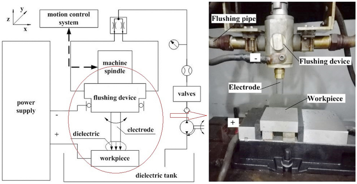
Experimental setup.
Experimental procedures
In order to study the performance of the arc milling of 50 vol.% SiC/Al matrix composites with a blasting erosion arc machining system, cavities with the same dimensions are machined and the electrode feeds in a layer milling mode. The machining cavities are 50 mm long, 20 mm wide and 3 mm deep. The main concerned machining performance is the MRR and the tool wear ratio (TWR). MRR is approximately calculated by the product of the layer milling feed rate, the width and the depth of the machined cavities. The TWR is defined as the ratio of the electrode corrosion volume to the removed workpiece volume. The experiments consist of four sets.
A fractional factorial experiment.
A full factorial experiment.
A comparison experiment between 50% SiC/Al and pure aluminum.
A comparison experiment between positive electrode machining (positive BEAM) and negative electrode machining (negative BEAM).
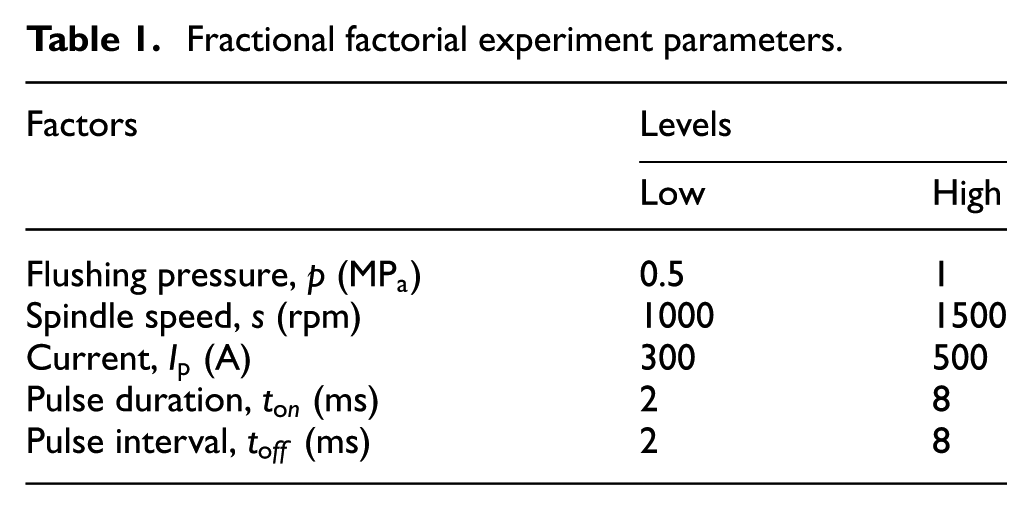
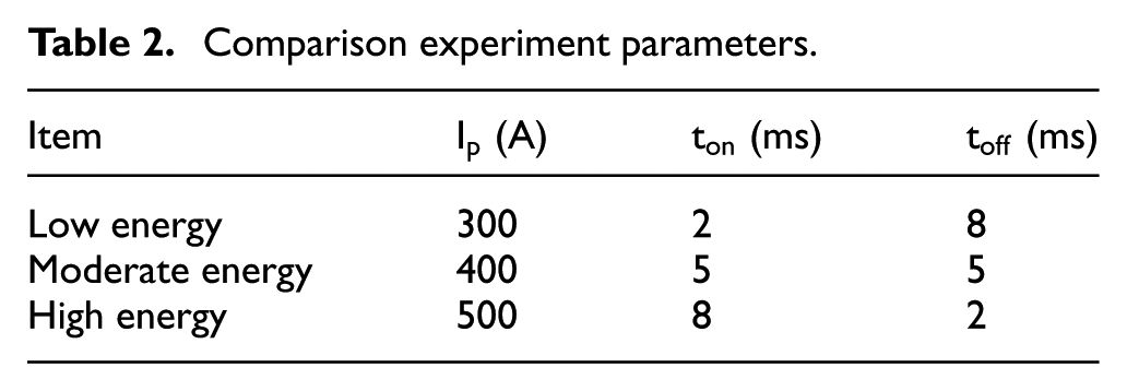
Experiment set 1 was a fractional factorial experiment, which was designed as a five-factor, two-level fractional factorial experiment by Minitab software, as listed in Table 1. The aim of the fractional factorial experiment was to study the main impact factors for MRR, including non-electrical factors (flushing pressure and spindle speed) and electrical factors (perk current, pulse duration and pulse interval). The parameters were selected in the range of the machine operation parameters and power supply. After the main impact factors were found, the follow-up full factorial experiment (set 2) was conducted to investigate the detailed relationship between the main impact factors and the machining performance. In order to study the influence of the SiC particles on the machining performance, experiment set 3 (comparison experiment between 50% SiC/Al and pure aluminum) was employed. The experiment includes low energy, moderate energy and high energy conditions as listed in Table 2. Finally, machining behaviors under different polarities were compared in experiment set 4, the parameters of experiment set 4 were chosen from experiment set 2.
Fractional factorial experiment parameters.
Comparison experiment parameters.
Experiments set 1 to set 3 were designed as negative electrode machining experiments (negative BEAM), which means the electrode was connected to the cathode, and the workpiece was connected to the anode. In experiment set 4, the polarity comparison experiment, the electrode was connected to the anode and the workpiece was connected to the cathode.
After the experiments, the machined workpiece was observed by a scanning electron microscope (SEM, type: COXIEM-30) and the cross-section was observed by a ZEISS metallographic microscope( Axio Imager A1m). Besides the compositions of the machined surfaces were analyzed by EDS (energy dispersive spectrometer, type: XFlash Detector 630M).
Results of experiments
Results of experiment set 1
The purpose of experiment set 1 is to find out the main impact factors of the MRR. The factors include non-electrical factors (flushing pressure and spindle speed) and electrical factors (perk current, pulse duration and pulse interval). The results are listed in Table 3.
Results of the fractional factorial experiment.
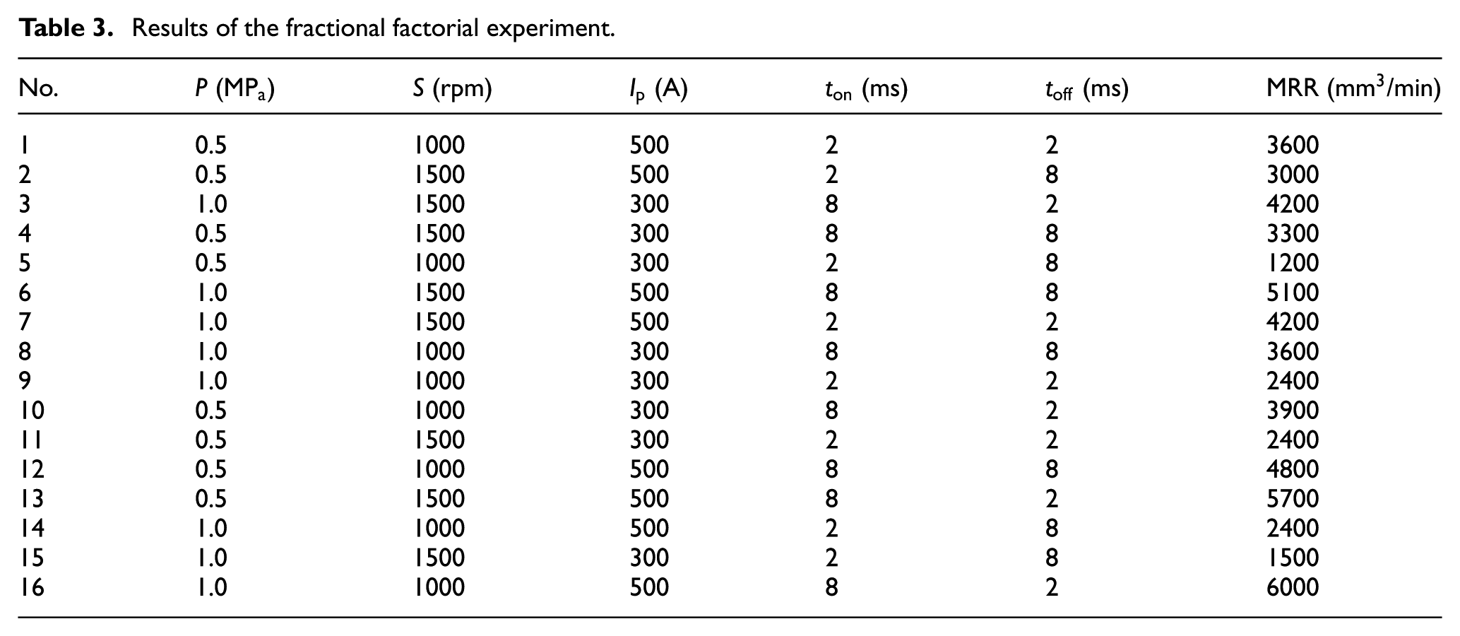
According to Table 3, the main effects of the MRR are shown in Figure 2. It can be concluded that the influence of the spindle speed (low level: 1000 rpm and high level: 1500 rpm), the dielectric flushing pressure (low level: 0.5 MPa and high level: 1.0 MPa) are not the main impact factors. With an increasing flushing pressure and spindle speed, the MRR also increases, but the trend is weakened compared to that of the electrical parameters (current, pulse duration and pulse interval). Consequently, in the following full factorial experiment, the spindle speed and the dielectric flushing pressure are constantly set to 1000 rpm and 1 MPa, respectively.
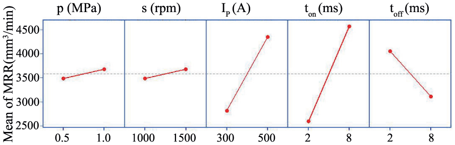
Main effects for the MRR.
Results of experiment set 2
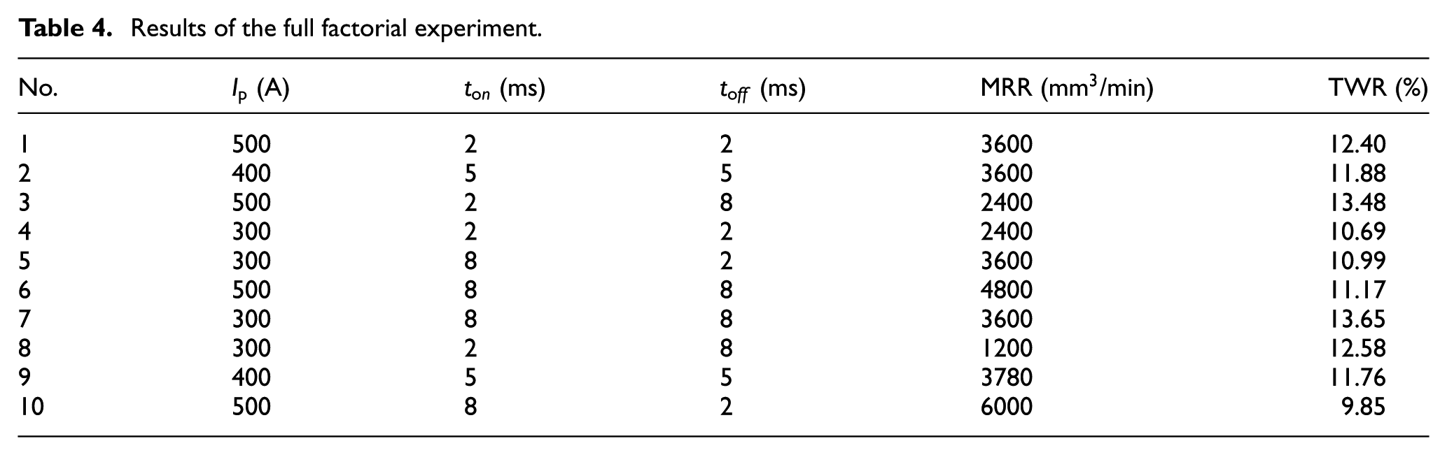
Experiment set 2 was designed as a three-factor, two-level experiment with two central points based on the results of experiment set 1. The factors were the current (low level: 300 A and high level: 500 A), the pulse duration (low level: 2 ms and high level: 8 ms) and the pulse interval (low level: 2 ms and high level: 8 ms). The results are listed in Table 4.
Results of the full factorial experiment.
Material removal rate
Figure 3 shows surface plot of MRR versus current, pulse duration and pulse interval.
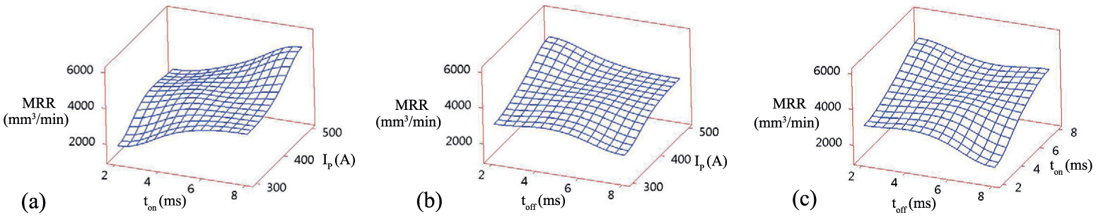
Surface plot of the MRR vs. (a) current and pulse duration,(b) current and pulse interval and (c) pulse duration and pulse interval.
From the surface plots, it can be concluded that the MRR increases with the current and the pulse duration, but declines with the pulse interval. Since the discharge energy is determined mainly by the discharge voltage, current and pulse duration, in the discharge process, the gap voltage is usually stable and the arc energy is determined by the product of the current and pulse duration. When the current is 300 A, the pulse duration is 8 ms and the pulse interval is 2 ms, the MRR is about 3600
Tool wear ratio
Figure 4 shows the surface plot of the TWR vs. current, pulse duration and pulse interval.
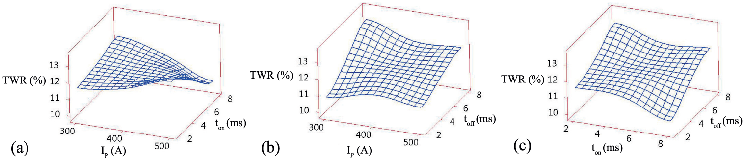
Surface plot of the TWR vs. (a) current and pulse duration,(b) current and pulse interval and (c) pulse duration and pulse interval.
The TWR has the opposite tendency to the MRR, that is, with an increasing of the current and pulse duration, the TWR declines, and with an increase of the pulse interval, the TWR increases. As mentioned above, when the current is higher, the pulse duration is longer and the pulse interval is shorter, the discharge energy will be larger and this results in a higher machining efficiency, which means more workpiece material can be removed per unit time. This is also a possible reason why the TWR declines with the increase of energy.
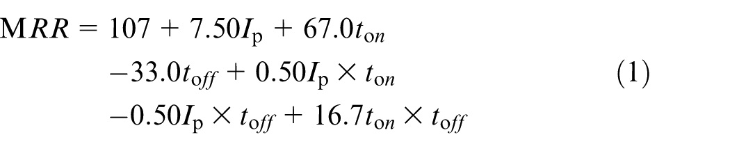
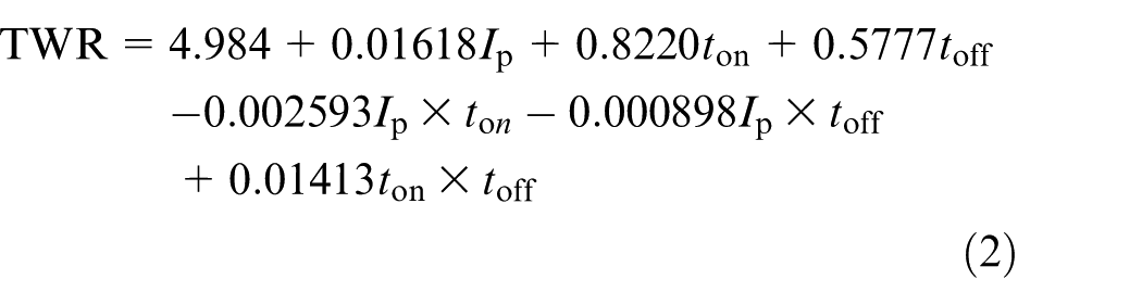
It is noted that, although the TWR varies under different machining conditions, it appears to be stable (around 10%). For instance, the minimum TWR is 9.86% when the current is 500 A, the pulse duration is 8 ms and the pulse interval is 2 ms, and the maximum TWR is 13.66% when the current, pulse duration and pulse interval are 300 A, 8 ms and 8 ms. A fitting formula of the TWR is given by regression analysis as following
Optimization of the MRR and the TWR
There are many methods (e.g. the integrated ant colony algorithm, response surface methodology and multi-objective optimization) can be used for the optimization of manufacturing processes.20–23 In order to magnify the MRR and reduce the TWR with a simple method, an optimization is conducted with the MATLAB optimization toolbox according to the MRR fitting equation (1) and the TWR fitting equation (2). The function used for the optimization is fmincon. The machining parameters are set in the range of power supply. The optimization model is given as

which is subject to
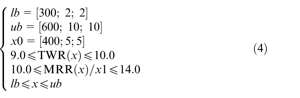
where
Optimized values and experimental verification.
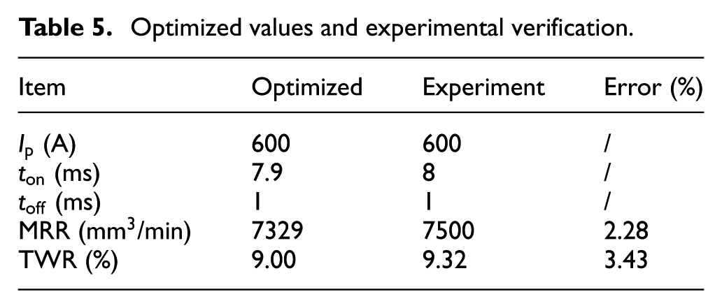
According to experimental results, when the current is 600 A, the pulse duration is 8 ms and the pulse interval is 1 ms, the MRR reaches about 7500
Results of experiment set 3 and the simulations
Experiment set 3 is a comparison experiment between 50 vol.% SiC/Al and pure aluminum. The purpose of this set is to study the influence of the SiC particles on the machining performance of BEAM.
Results of the comparison experiment
The performance comparison between 50% SiC/Al and pure aluminum is shown in Figure 5.
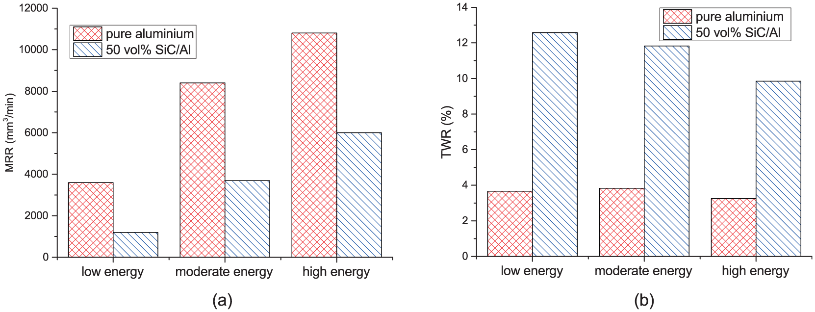
Performance comparison between 50% SiC/Al and pure aluminum (a) MRR and (b) TWR.
Regardless of the discharge energy levels, it is obvious that the MRR of 50 vol.% SiC/Al is much lower than that of the pure aluminum, and the TWR of the 50 vol.% SiC/Al is much higher. It indicates that SiC particles have negative influence on the machining performance. Because the material removal mechanism of the BEAM is directly related to the heat effect, and the heat characteristics of the SiC particles are distinct from the matrix material (aluminum) fractions.
Simulations of heat transfer
In order to illustrate the different machining performance of pure aluminum and 50 vol.% SiC/Al, single discharge heat transfer simulations are employed based on COMSOL Multi-physics software. The Gaussian distribution heat flux q(r) is used as a heat source,24,25 which is expressed as
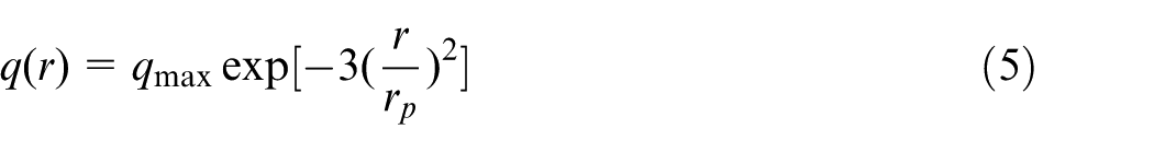
where
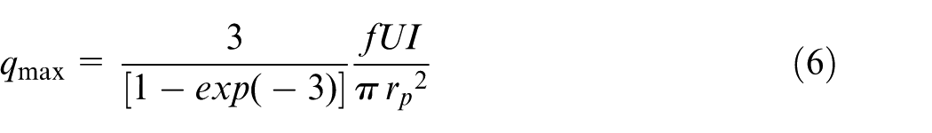
where
Besides the heat flux, the materials heat characteristics are also necessary in the simulation. Thermal resistance and material heterogeneity is not considered to simplify calculation. The heat capacity of SiC is the function of the temperature
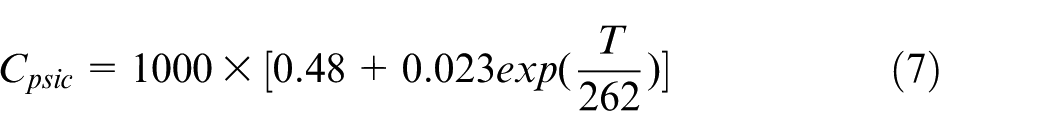
For 50 vol.% SiC/Al matrix composites, an approximate calculation is given by

where
Although the heat conductivity of SiC is also regarded as a function of the temperature
Parameters for the simulations.
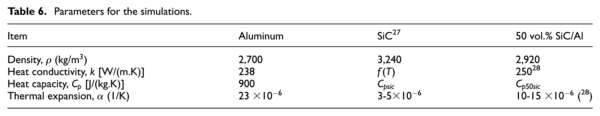
Figure 6 shows the heat transfer simulation. When the same heat sources are applied to the pure aluminum and 50 vol.% SiC/Al geometric models respectively, the temperature of the pure aluminum rises much faster than that of the 50 vol.% SiC/Al. As depicted in equation (7), the SiC heat capacity grows with the increasing temperature, that is, when the temperature rises, more heat is needed which brings negative influence on the further increasing of workpiece temperature. Consequently, compared with pure aluminum, when machining 50 vol.% SiC/Al under the same conditions, the performance is compromised.
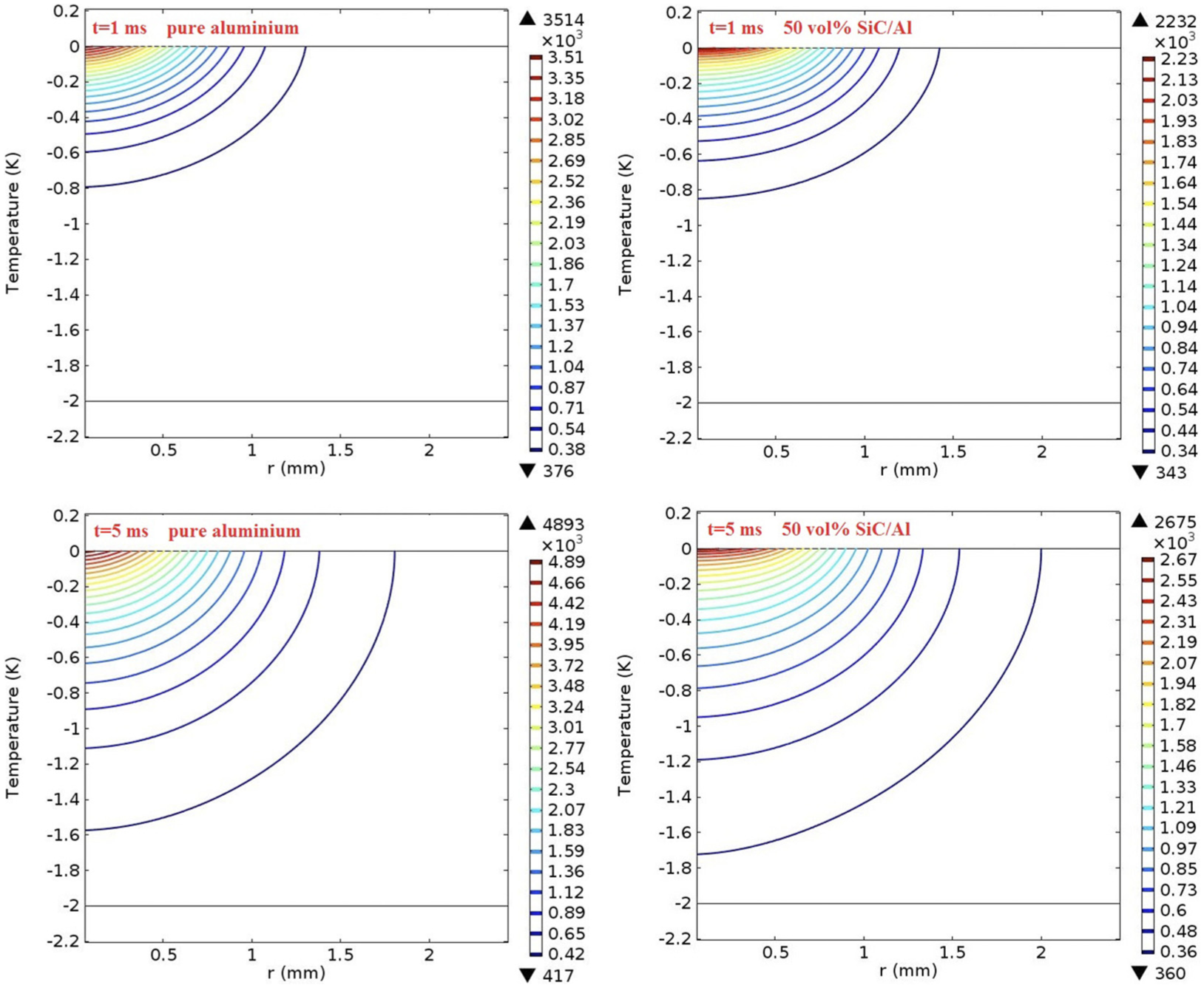
The heat transfer simulation.
Results of experiment set 4
Experiment set 4 is a polarity comparison experiment. The aim was to investigate the machining performance under different machining polarities.
Comparison of the machining performance
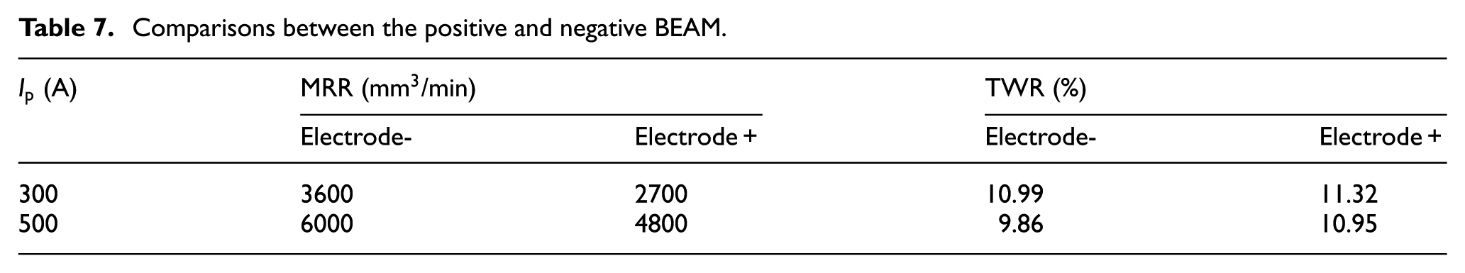
Table 7 shows a group of comparisons between the positive and negative BEAM when the current is 300 A and 500 A (
Comparisons between the positive and negative BEAM
Comparison of the surface integrity
Machined surface comparisons are shown in Figure 7. It is disclosed that the discharge craters become larger with higher energy both under the negative BEAM and the positive BEAM. And the surfaces machined by the positive BEAM are usually smoother and brighter than that of the negative BEAM machined surfaces. SEM observation of the machined surfaces are shown in Figure 8. SiC particles can be found on the positive BEAM machined surfaces, while they are not obviously found on the negative BEAM machined surfaces. A possible reason is the different physical characteristics of the aluminum and SiC: the melting points of aluminum and SiC are about 930 K and 3000 K (decomposes), respectively. In the negative BEAM, workpiece is connected to anode and anode is distributed more energy, SiC particles tend to absorb more heat then decompose, and can not be observed.
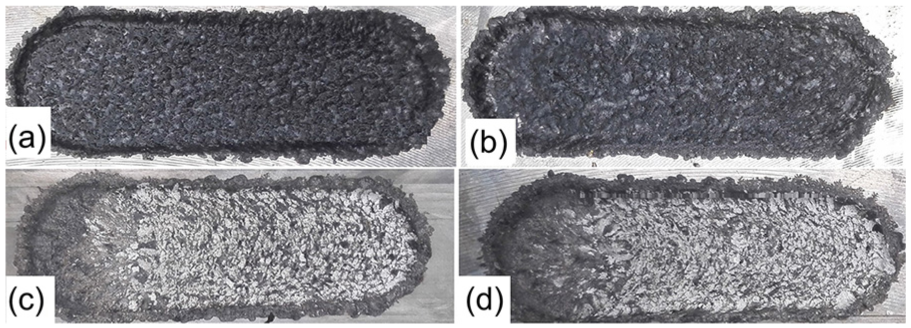
Machined surface comparisons for (
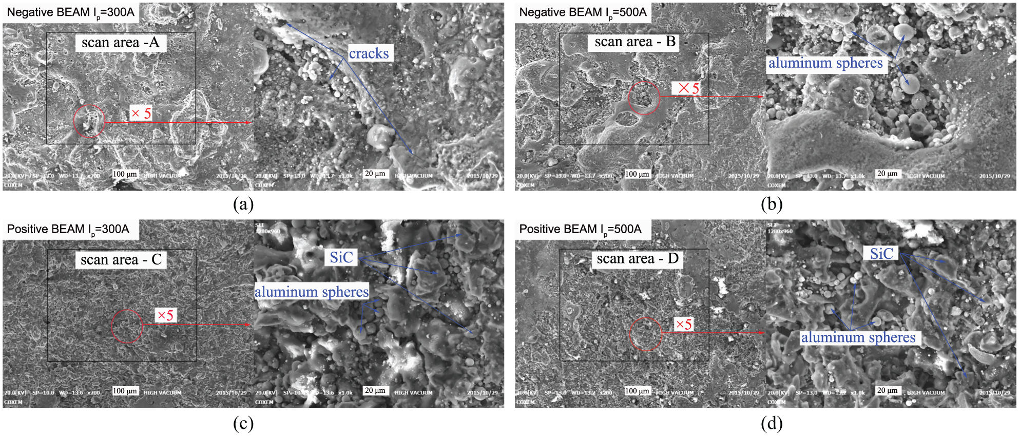
SEM observation of the machined surfaces for (
Figure 9 shows the EDS results. More Al element can be found in the positive BEAM machined surfaces, which means that less matrix material is oxidized in positive BEAM .
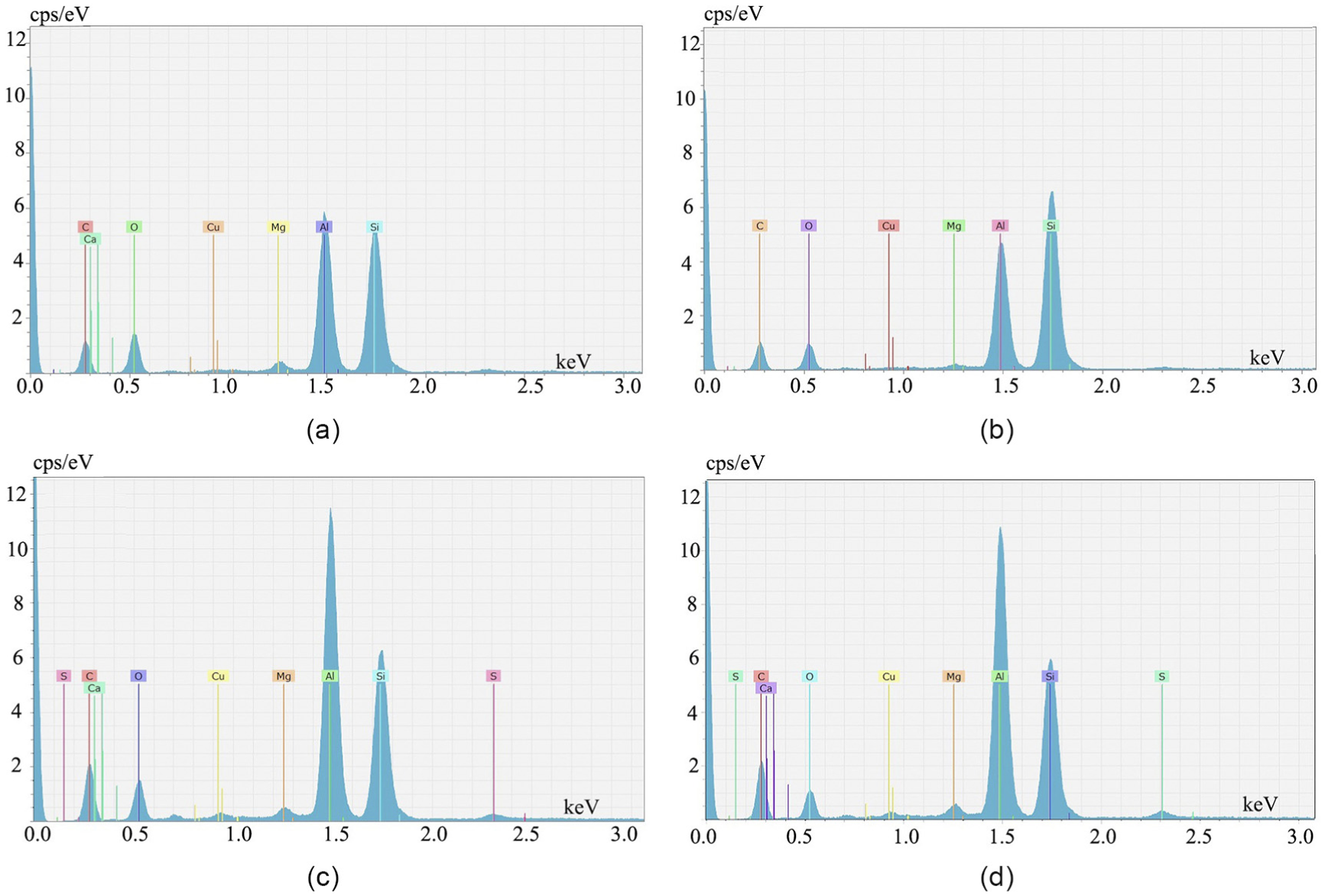
EDS results for (
It is noted that cracks can be found under both the negative BEAM and the positive BEAM conditions. Because the discharge plasma heats the workpiece in a very short time and the temperature of the flushing dielectric is as low as the environment, the heated workpiece is easy to shrink and causes cracks. Further, observation of the cross-sections of the machined workpiece disclosed that the higher current usually results in a thicker heat effect zone. And, in the negative BEAM, the heat effect zone is thicker than that of the positive BEAM. For instance, in high energy machining (current 500 A) with a negative electrode, the average heat effect zone is thicker than 300
Sample machining
Figure 10 shows a 3D model and the workpiece machined with BEAM, the dimension of the workpiece is 65 mm
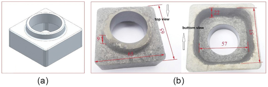
Sample machining for (a) the 3D model and (b) the workpiece machined with BEAM.
Conclusions
In order to improve the machining efficiency of high fraction (50 vol.%) SiC/Al matrix composites, BEAM has been adopted and factorial experiments have been conducted. Based on the experimental results and analysis, the following conclusions have been drawn.
BEAM can be used for the machining of 50 vol.% SiC/Al matrix composites with high efficiency, the MRR can be as high as 7500
The SiC particles have a negative influence on the machining efficiency and the TWR due to their temperature dependent heat characteristics.
The MRR of the negative machining is higher than that of the positive electrode machining, and the TWR of the negative machining is a little lower.
The machined surface of the negative electrode machining is coarser compared to that machined by the positive BEAM, and the heat effect zone of the negative electrode machining is much thicker than that of the positive electrode machining.
Footnotes
Declaration of conflicting interests
The author(s) declared no potential conflicts of interest with respect to the research, authorship, and/or publication of this article.
Funding
The author(s) disclosed receipt of the following financial support for the research, authorship, and/or publication of this article: This work was supported by the Natural Science Foundation of China (51235007, 51575351), the innovative group grant of NSFC (51421092), the State Key Laboratory of mechanical and vibration Focus Fund, Shanghai Jiao Tong University (MSV201305) and the grant of USCAST (2015-19).