
Abstract
Study on mechanics of milling of thin-wall components using a helical end mill is important in view of its complex nature and prominent applications in aerospace, automobile and electronics areas. This article presents a realistic three-dimensional, thermo-structural, finite-element-based mathematical model for thin-wall milling of aerospace grade aluminum alloy. Lagrangian formulation with explicit solution scheme was employed to simulate the interaction between helical milling cutter and the workpiece. Behavior of the material at high strain, strain rate and temperature was defined by Johnson–Cook material constitutive model. Johnson–Cook damage law and friction law were used to account for chip separation and contact interaction. Experimental work was carried out to validate the results predicted by the mathematical model. The developed model predicted the forces in radial, feed and axial directions with errors of 14%, 26% and 33%, respectively. The prediction errors for deflections at top, middle and bottom portions of thin wall were within 11%–39%. The simulated chip dimensions were in good agreement with experimental results while the computed cutting temperature varied by 17% with respect to the experimental value. Overall, it was found that the developed model predicts the process responses with fair and acceptable prediction accuracy. Using the developed model, a study on the effect of process parameters on the performance parameters, namely cutting and thrust forces, stress distribution, cutting temperature, part deflection and chip morphology was carried out, which is not possible using a two-dimensional orthogonal or oblique cutting model. It was found that the developed three-dimensional mathematical model provided very useful insights into the complex physical interaction of helical cutting tool and workpiece during thin-wall milling of aerospace alloys.
Keywords
Introduction
Thin-wall components are widely used in aerospace, automobile and electronics industries. 1 These components have low rigidity as they have large surface area as compared to their thickness. Nowadays, high-speed thin-wall machining is gaining popularity due to its merits such as low cutting forces, low cutting temperature, reduced machining time and generation of better quality of surface.2,3 However, it requires high capital investment which may not affordable by the small-scale industries. Therefore, it is essential to explore the employment of conventional low to medium duty computer numeric control (CNC) machining centers for manufacturing of quality thin-wall structures.
During the machining operation, thin walls deflect under the action of milling forces which in turn affects the quality and accuracy of the work-part. To reduce the form error generated due to the deformation, in general, a trial and error method is adopted. In this method, the cutting parameters are tuned by carrying out a number of experiments. However, conducting experiments is time-consuming, tedious and error prone. In view of this, if the deflection is predicted beforehand, effective counter measures can be undertaken to obtain the desired process performance, that is, manufacturing of a dimensionally accurate finished component with good surface quality. A need was thus identified to develop a realistic three-dimensional (3D) numerical model to predict the process responses which will help for better control of the process parameters during the actual cutting operation.
The literature reports various attempts to model and analyze the thin-wall milling operation using analytical and numerical techniques. Budak and Altintas 4 modeled the peripheral milling operation by considering the workpiece and cutting tool as a plate and an elastic beam member, respectively. They investigated the workpiece dimensional errors during the process. A cutting force model was developed to predict the deflection of thin-wall part by taking into consideration the immersion angle and chip thickness without due consideration to the material properties.5,6 The model was further modified by incorporating the effects of material removal and workpiece deflection.7,8 Rai and Xirouchakis 9 conducted comprehensive numerical studies to analyze the cutting force components, workpiece temperature distribution, part deflection and stresses in the machining of thin-wall components. Aijun and Zhanqiang 10 proposed analytical correlations to predict the deformation of low rigidity part considering the thin-wall part as a plate. Subsequently, part deformation was simulated using linear loads as input without due consideration to the material properties. Tănase et al. 11 carried out experimental and numerical analysis to study the stresses generated in the machining of parts having thin walls.
Few attempts have also been reported on two-dimensional (2D) finite element (FE) simulation of milling process. Özel and Altan 12 presented a process simulation model for high-speed flat end milling of P-20 mold steel to predict the cutting forces, tool stresses and temperatures. Later, a study on influence of friction models in FE simulations of machining process was carried out using a Lagrangian FE formulation. The model was able to simulate the continuous chip formation process in orthogonal cutting of low carbon free-machining steel. 13 Thepsonthi and Özel 14 studied the performance of carbide micro-end mills with cubic boron nitride (cBN) coating. 2D plane strain finite element models (FEMs) were developed to predict chip formation, cutting forces, temperature and wear rates during the process. The simulation results were utilized for estimating tool life using a sliding wear rate model. It was reported that cBN-coated carbide tool provided better resistance to wear and worked at higher temperatures compared to the uncoated tool. Experiments were conducted to validate the model. Experimental data were collected and a multi-objective particle optimization model was developed to minimize the surface roughness and burr formation. 15 Data obtained from experimental and simulation work were utilized to develop an integrated method for selection of toolpath and optimum process parameters. 16 Agmell et al. 17 developed a fully coupled thermo-mechanical 2D simulation model for orthogonal cutting. The model was validated by comparison of the simulated values with experimental data for several different process parameters, such as the feed force, the cutting force, the chip thickness ratio, the relative deformation widths and the temperature distribution. Ginting and Nouari18,19 performed dry milling of aerospace titanium alloy Ti-6242S. They investigated the suitability of uncoated cemented carbide tools in ball-end milling of titanium alloy under dry cutting conditions. Optimal cutting conditions were determined for dry milling of the same alloy by utilizing the FEM simulation. Meanwhile, Rech et al. 20 investigated the influence of cutting edge wear behavior of powder metallurgical high-speed steel (PM-HSS) milling inserts experimentally. Simultaneously, Lagrangian thermo-visco-plastic-based 2D FE cutting simulations were carried out to analyze the tool-stress distributions within the tool coating and substrate based on which the optimum cutting edge radius for minimal stresses was determined. Li et al. 21 proposed a FE-based study on residual stresses induced by high-speed end milling of hardened steel SKD11. In order to ensure a stable cutting during the finish mode of operation, the effect of residual stress was examined numerically. A 2D fully thermo-mechanical coupled FEM was employed to evaluate the stresses remaining in a machined component. The model was developed based on the effective rake angle and the variable undeformed chip layer. Adetoro and Wen 22 utilized FE tool to simulate the cutting process and to determine both the average and instantaneous cutting force coefficients. The model was found to be accurate in predicting the cutting forces.
The literature also reports some research work on the development of 3D FE-based numerical simulations for milling operation. Bacaria et al. 23 developed a transient numerical model of metal cutting for milling operation. The FEM took into account dynamic effects, thermo-mechanical coupling with damage criterion and contact with friction. Pittalà et al. 24 carried out FE-based simulation of face milling operations using a 3D milling insert. Soo et al.25,26 successfully simulated the high-speed ball nose end milling process using a 3D FEM. Chip shape, cutting forces and temperature were simulated for Inconel 718 workpiece. Saffar et al. 27 employed 3D FE simulations to predict cutting forces and tool deflection during end milling operation. Results were compared with theoretical relationships and the model was found to be more accurate. It was noted that material properties in the simulations defined based on the Johnson–Cook (J-C) theory were better compared to the theoretical relationships where properties were simply defined using the constant material coefficient. Similarly, Maurel-Pantel et al. 28 also conducted a 3D FE simulation of shoulder milling operation by implementing J-C plastic material model to study the cutting forces and chip formation during the process. Wu and Zhang 29 extended the model by including damage constitutive law in addition to the material model to define the chip separation in the milling of titanium alloy. Chen et al. 30 developed a FEM for inclined ball-end milling. They utilized Cockcroft-Latham criterion for chip formation study. Asad et al. 31 investigated the effects of cutting speed and depth of cut on chip morphology and surface finish for down-cut milling case. 3D simulations were developed for roughing, semi-finishing and finish cutting operations of A2024-T351. Mabrouki et al. 32 used FE-based methodology to study the physical phenomenon of chip formation varying with feed rate and cutting velocity. Wang et al. 33 presented a 3D FEM to simulate the high-speed end milling of Ti6Al4V titanium alloy. Zorev’s friction model was used to determine the frictional behavior of the tool–chip interface in addition to J-C material constitutive model and J-C shear failure criterion. Cutting forces in three directions were predicted under different cutting conditions, and chip evolution and morphologies of different cutting parameters were also analyzed. Wan et al. 34 developed a FE-based numerical model to simulate the flexible peripheral milling and predicted the static form errors in thin-wall workpieces. In this work, irregular FE meshes were used to enhance the flexibility and robustness of the simulation approach. The developed algorithm was found to be realistic as it considered two important cutting aspects: first, the engagement of cutter elements with the workpiece, and the second was the iterative corrections of radial and axial cutting depths simultaneously. 35 Pervaiz et al. 36 improved the efficiency of dry milling of Ti6Al4V titanium alloy by conducting systematic machining experiments and FE-based simulations. Ji et al. 37 investigated the process of precision milling of a hole in a titanium alloy Ti-6Al-4V workpiece using a 3D FEM. Thepsonthi and Özel 38 investigated the influence of tool cutting edge wear on the process performance during micro-end milling. 3D model was developed for full-immersion, half immersion up and down milling conditions. Chip shapes were simulated and compared with experimental work. Results indicated that tool wear had a significant impact on the cutting force, cutting temperature, tool wear rate, chip flow and burr formation. Jiao et al. 39 carried out a transient 3D simulation to predict the temperature field on the machined surface in single tooth and multi-tooth milling using the FE method.
The literature also reported some important studies on the development of cutting force models and optimum process conditions for efficient milling operation. Hosseini et al. 40 proposed the use of serrations on the end mills to suppress the vibrations occurred during machining operation. They also developed a mechanistic-based numerical model of the same and conducted successful simulations. Wan et al. 41 developed a ternary-mechanism-based model to predict the cutting forces in flat end milling process. The force model was equipped with realistic machining phenomena such as influence of chip removal, flank rubbing and bottom cutting. Cutting force coefficients were calibrated using experimental data. Moreover, Wan et al. 42 presented a unified instantaneous cutting force model to predict the cutting forces for flat end mills with variable geometries. The model efficiently determined the shear stress, shear and normal friction angles. Dong et al. 43 estimated cutting force coefficients required for analytical simulation of milling of thin-walled part using single cutter with varying tooth radii. The actual cutting force coefficients were derived based on the radii error of cutter teeth which were computed from nominal milling forces and cutting force coefficients. Pan et al. 44 proposed a cutting force model for end milling of titanium alloy (Ti6Al4V) with polycrystalline diamond tools. Sun et al. 45 carried out an experimental study to measure cutting temperature in milling operation of Ti6Al4V using a semi-artificial thermocouple. The results were utilized to validate predictions given by an analytical model. Chen et al. 46 also developed a force model for simulation of orthogonal cutting of Ti6Al4V. The model incorporated J-C material model to consider the effect of material strength and temperature rise. Yildiz 47 developed a novel hybrid optimization technique, namely hybrid immune and hill climbing local search algorithm which was successfully employed to obtain optimum parameters of multi-milling process. Later, he developed another hybrid technique which was based on differential evolution algorithm and receptor editing property of immune system. The proposed methodology was successfully validated for milling operation. 48 Moreover, to test the crashworthiness of thin-wall structures, Yıldız et al. 49 developed gravitational search and Nelder–Mead-based hybrid optimization algorithm. The results showed that the developed hybrid approach was very effective to assess the crash performance of the vehicle components and thin-wall structures.
From the reported literature, it was concluded that a significant amount of work is reported on 2D and 3D simulations of bulk milling operation. However, the helical thin-wall milling process is more complex than the traditional milling process. Scant work is reported on 3D thermo-structural modeling and simulation of machining of low rigidity thin-wall components. In view of this, in this work, a Lagrangian-based 3D FE-based numerical model has been developed to simulate the deflection of workpiece during the thin-wall machining of aluminum 2024-T351 alloy. The developed model was aimed to predict the cutting forces, temperature, stress distribution and chip formation in the workpiece by employing the realistic milling tool geometry and process parameters. Subsequently, milling experiments were carried out to validate the established model. Details of the model development are presented below.
FE modeling and simulation of thin-wall machining process
During the milling process, the material is removed from the workpiece using a rotating cutter. The most commonly used milling operations are peripheral (or end) milling and face (or plain) milling. Generally, peripheral milling is a common process used in aircraft thin-wall component machining. The thin-wall sections are deformed due to the influence of forces developed during tool–workpiece interaction and the heat generated during cutting. The cutting force developed depends upon various process parameters; therefore, the accuracy of the component depends upon the proper selection of the process parameters during machining. In the machining process, heat is generated due to inelastic deformation and frictional contact between the workpiece and the tool. The heat generated directly influences the material properties. Therefore, it is essential to couple the mechanical and thermal responses to obtain the solution for such a problem. In this work, a fully coupled thermo-mechanical analysis of thin-wall milling operation has been attempted.
Mechanical analysis
The differential equation of motion governs the mechanical response and is given by

Equation (1) is rewritten in matrix form as

where ρ is the mass, c is the damping coefficient, k is the stiffness coefficient,

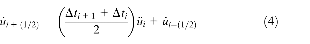
Velocity change is calculated by integrating acceleration term explicitly through time using central-difference method. The change in velocity obtained is then added to velocity from the middle of the previous step and is used to calculate the velocities at the middle of the current step
Displacement is calculated by integrating velocity through time, which is then used to update the displacements at the end of time step

Thermal analysis
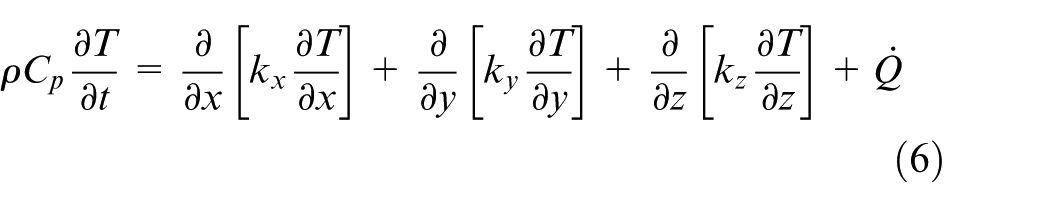
The governing equation which outlines the transient heat transfer process during machining process is written as
where

where

Forward difference integration scheme applied to the nodal temperature rate gives
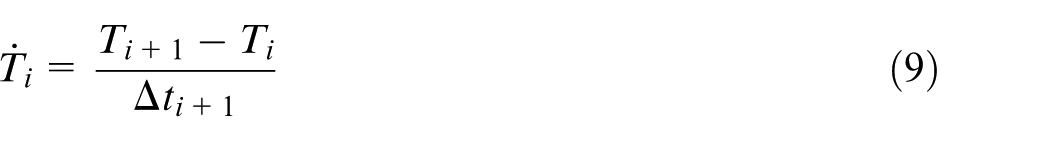
Equation (9) is rewritten as follows

Explicit expression for nodal temperature rate can finally be written as follows

Total volumetric heat generation rate

where

where

where hc is the heat transfer coefficient whose value is 20 W/m2°C,
52
workpiece temperature
Geometrical modeling, boundary conditions, mesh configuration and cutting conditions
To solve this mathematical model, first the geometric models of the cutting tool and the workpiece were developed. The thin-wall workpiece was modeled as an inverted cantilever structure as shown in Figure 1. The end mill was also modeled in 3D based on the actual tool parameters those are listed in Table 1.
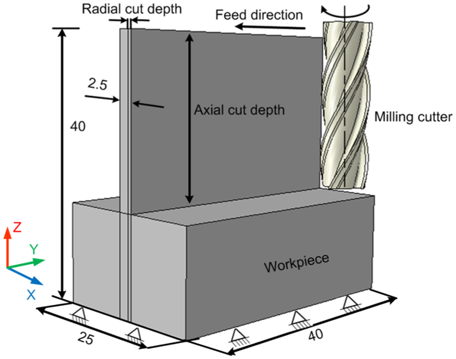
Geometric model with specified boundary conditions.
Cutting tool parameters.
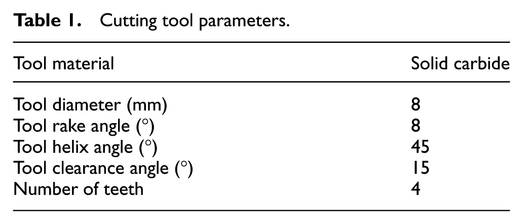
Figure 1 also outlines the boundary conditions provided in the model. Workpiece was modeled as a structure with bottom portion being constrained, while the other three ends are free. The influence of vibrations of thin-wall structure that occurs during the machining was not considered in this work. The four teeth milling tool was provided with two motions, namely linear motion along the feed direction and rotational motion about its axis. A single full axial depth pass for finish operation was considered for the present simulation study. The initial temperature of the tool and workpiece was set at room temperature. Heat loss to the environment from the tool and workpiece interface was primarily considered by the convection. Figure 2 shows the meshed models of the tool and the workpiece. Both the workpiece and the tool were discretized by employing a 3D solid brick element, C3D8RT. It is an eight-node linear brick element with reduced integration and hourglass control. The mesh density was kept higher at the cutting tool and workpiece interaction region to account for the chip formation. The tool and the workpiece were discretized into 12650 and 293745 elements, respectively. The cutting conditions employed are listed in Table 2. ABAQUS™ explicit software, a commercial FEM solver, was used to solve this problem. It took about 340 h to solve this problem using a 3.9 GHz, 4 GB RAM processor.
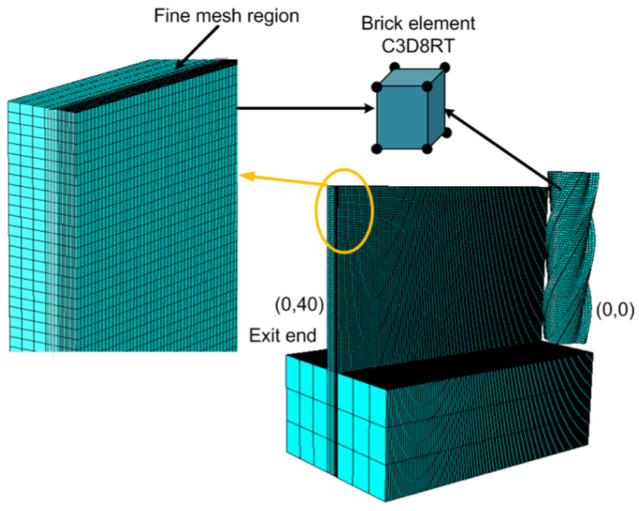
Workpiece and tool meshing with element type.
Cutting condition during machining.
Material properties and material constitutive model
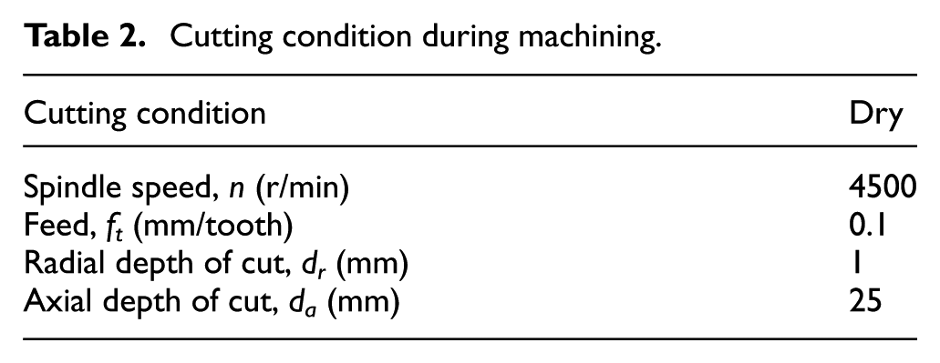
In the developed 3D model, the workpiece was modeled as an elastic-plastic material and the end mill was considered as a rigid body. During the machining process, the work material undergoes high plastic deformation which results in the rise in its temperature. The thermo-viscous plastic behavior of the material was modeled using J-C constitutive model. It is a flow stress model which represents the material behavior under the high strain, strain rate and temperature conditions. The J-C flow stress model is expressed by
where A (MPa) is the initial yield stress of the material, B (MPa) is the hardening modulus, C is the strain rate dependency coefficient, n is the work-hardening exponent, m is the thermal softening coefficient,
Johnson–Cook material parameters values for A2024-T351. 32

Workpiece material failure criteria
It was desired to simulate the material ductile failure with high strain, strain rate and temperature effects. J-C shear failure criterion was used to model the chip detachment. 54 Figure 3 shows the progressive damage degradation curve obtained from a uniaxial stress–strain response of a ductile metal. Chip formation due to the shear deformation occurs in two stages: first, the failure initiation and the second is the failure evolution. During the initial phase, material response is linear elastic (stages 1 and 2) which is followed by plastic yielding with strain hardening (stages 2 and 3). Beyond point 3, material loses its load carrying capacity until it undergoes the fracture (stages 3 and 4). Point 3 represents the damage initiation point, which is referred to as damage initiation criterion. Complete failure of the material occurs at point 4. Deformation occurring in final stage (stages 3 and 4) is governed by evolution law which is based on fracture energy principle. 55
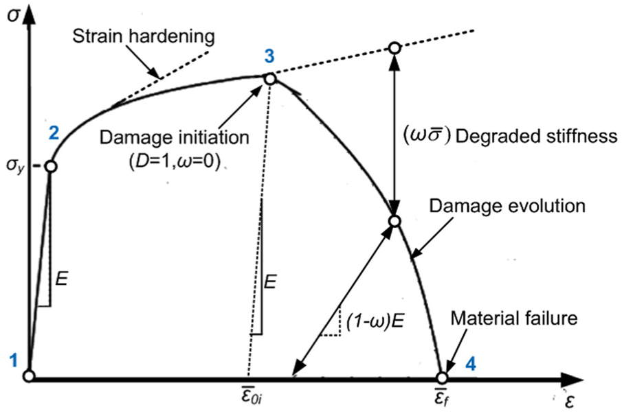
Stress–strain curve with progressive damage degradation. 32
Damage in the element is initiated by scalar damage parameter D, which is defined as the sum of the ratio of the increments in the equivalent plastic strain
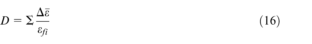
The equivalent strain at failure initiation
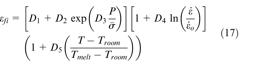
where P is the hydrostatic pressure and
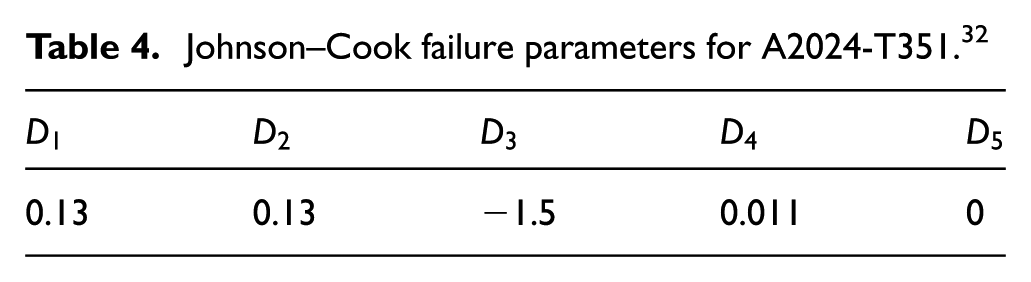
Johnson–Cook failure parameters for A2024-T351. 32
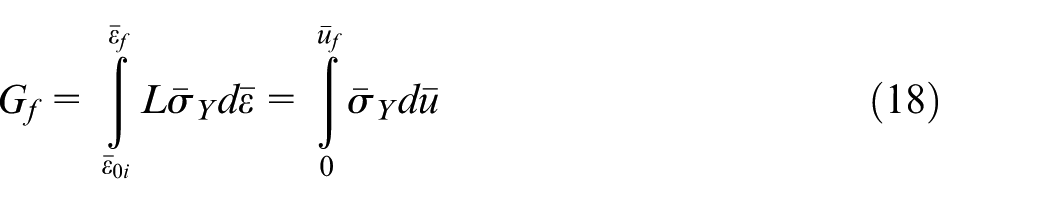
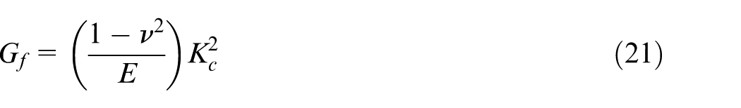
When ductile material damage occurs, the stress–strain relationship no longer accurately represents the material behavior. After the damage initiation, the use of stress–strain relation causes strong mesh dependency which is based on strain localization. This reduces the energy dissipation as the mesh becomes smaller. Influence of mesh dependency on energy dissipation can be reduced using the Hillerborg’s fracture energy proposal. 32 The damage evolution is based on Hillerborg’s fracture energy Gf required to open a unit area of crack and is defined as
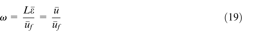
The damage evolution parameter is defined in the form of a scalar stiffness degradation parameter ω as given by
where
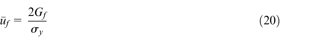
where
where
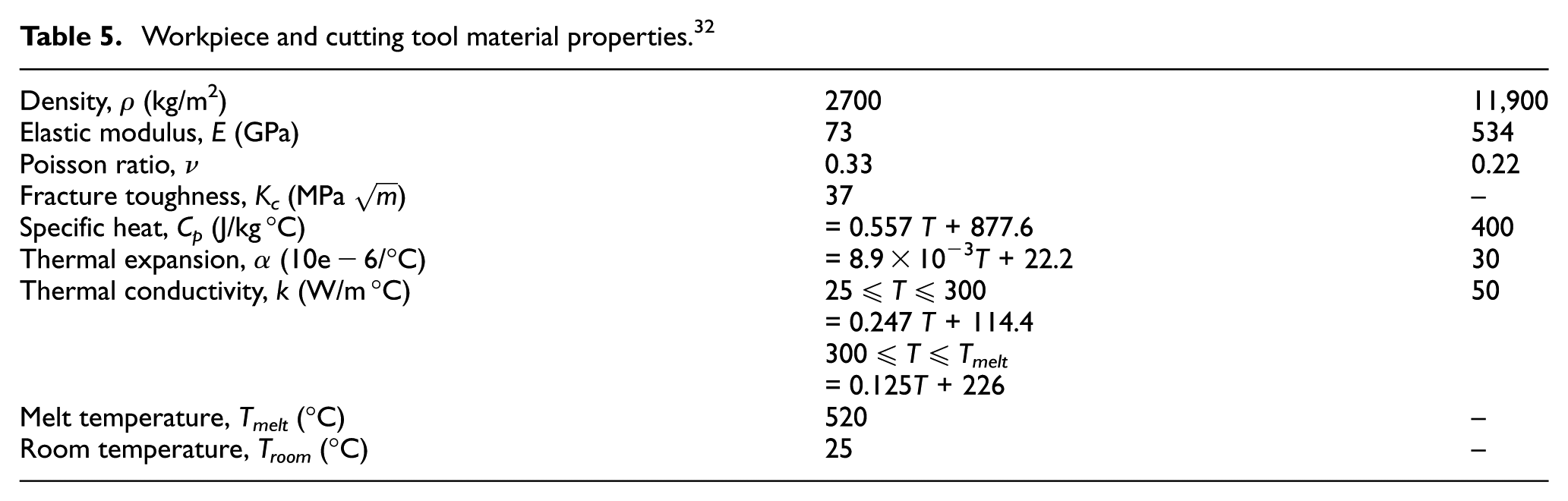
Workpiece and cutting tool material properties. 32
Workpiece and cutting tool contact model
The friction condition at the tool and workpiece interface influences the cutting forces, temperature, machining quality and tool wear. The contact between the cutting tool and the workpiece was defined using modified coulomb friction model. As per this model, the contact between the chip and the rake surface region can be divided into two regions, namely the sliding region and the sticking region. 29 Sticking friction occurs very near to the cutting edge in contact with the workpiece and the sliding friction occurs far away from the contact area. The sliding region obeys the Coulomb friction law. In the sticking region, the shear stress τ is equal to the critical frictional stress. The modified coulomb law is defined by the following equations


where
Experimental validation of mathematical model and preliminary results
After the development of the mathematical model, experimental validation of the simulation was carried out using a three-axis CNC vertical machining center (VMC). Figure 4 depicts the details of the experimental setup developed. The experimental setup was mounted on the VMC work table. The workpiece was clamped in a workpiece holder, which was fixed firmly on a piezoelectric sensor based three-component dynamometer (Kistler 9272B). Dynamometer was employed to measure the three components of milling force (Fx, Fy and Fz). The dynamometer was mounted firmly on to the base plate of the machine tool. For the data acquisition (DAQ), the dynamometer was connected to a computer through a force measurement multi-channel charge amplifier (type 5070A). The data sampling rate was set to 500 Hz per channel. The component Fx is normal to the machined wall surface. The component Fy is oriented along the direction of feed movement and the Fz component is along the tool’s axis. Temperature was recorded using a K-type thermocouple embedded in the workpiece. The thermocouple was connected to the Agilent-temperature DAQ system for the data acquisition. The workpiece deflection was measured by Solartron linear variable differential transformer (LVDT) sensor.
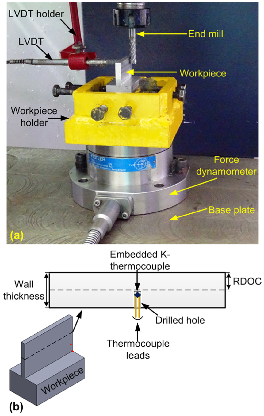
Experimental setup: (a) workpiece and force dynamometer and (b) thermocouple placement for temperature measurement.
Milling forces during thin-wall machining
Using the developed experimental setup, force components, namely radial force Fx, feed force Fy and axial force Fz, were recorded for a typical process condition as mentioned in Table 2. For the same process condition, a numerical simulation using the developed mathematical model was carried out. Figure 5 shows the comparison between the simulation predictions and the experimental results. The dotted lines represent the cutting forces in three directions which are obtained experimentally in the stable region, while the solid lines represent the respective simulation results. From the plot, it is observed that the forces predicted by the numerical model are in good agreement with those obtained in the experimental study. The average prediction errors were noted to be 13.93%, 25.74% and 32.68% in radial, feed and axial directions, respectively. Lower values of force predicted by numerical simulation can be attributed to the factors such as consideration of isotropic nature of material properties, stress-free work material and absence of tool vibration and tool run-out. It was observed that the prediction error of Fz is quite high in comparison with that of Fx and Fy. It is because the magnitude of Fz is smaller and it is more sensitive than the forces generated in the other directions. It is difficult to analyze the cutting action occurring around the tool tip. Also, the factors such as re-cutting of chips and ploughing of cutting tool edges on the work surface result in the generation of fluctuating force values. However, the trends of variations of experimental and numerical forces are matching. It can be seen that the forces are fluctuating with the time. This is due to the fact that during the cutting process, the material softens due to the rise in temperature which reduces the force values. As the magnitude of force decreases, the heat production also reduces which in turn affects the metal softening effect that further leads to rise in cutting forces.
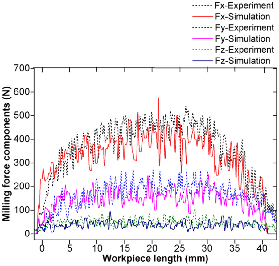
Comparison of milling forces Fx, Fy and Fz during numerical simulation and experimental validation.
Part deflection and form error
During the machining process, the thin-wall part deflects due to low rigidity under the action of cutting forces. Here, the deflection occurring is measured in the negative X-direction as shown in Figure 6.
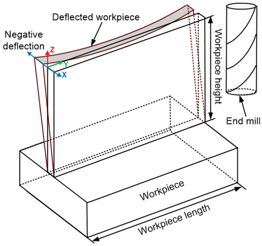
Thin-wall in-process deflection.
Figure 7 shows the variation of deflection along the workpiece length for a thin-wall component. It can be seen that maximum deflection occurs at the top edge of the wall in comparison to that at the base of the wall. It is because the rigidity of the top edge of the workpiece is less as compared to that of the thin-wall base. Base material has sufficient rigidity as it is firmly supported by the bulk material. It can also be observed that experimentally obtained deflection values are slightly on the higher side than those obtained in the simulations. Errors at top, middle and bottom are 10.82%, 16.85% and 38.56%, respectively. However, the trends of variations are found to be very well matching.
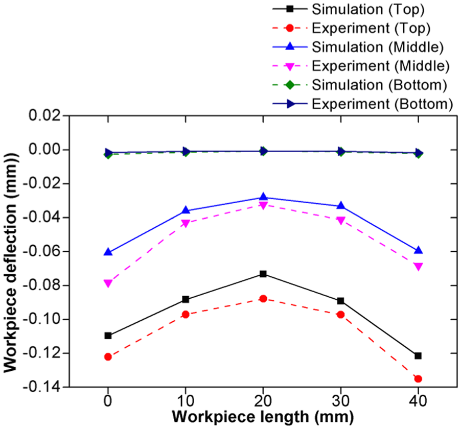
Comparison of numerical and experimental maximum deflection along the along the length of workpiece.
Figure 8 shows that the variations in deflection along the height of the workpiece at the end of milling operation. It can be noted that maximum deflection occurs at the two ends of the wall in comparison to that at the center. It is because the ends are less stiff and deflect readily under the action of cutting forces. The center portion has sufficient rigidity as it is supported by the material all around. Simulation prediction errors at the entry, center and exit of the tool contact with the thin wall are found to be 11.48%, 12.4% and 15.4%, respectively.
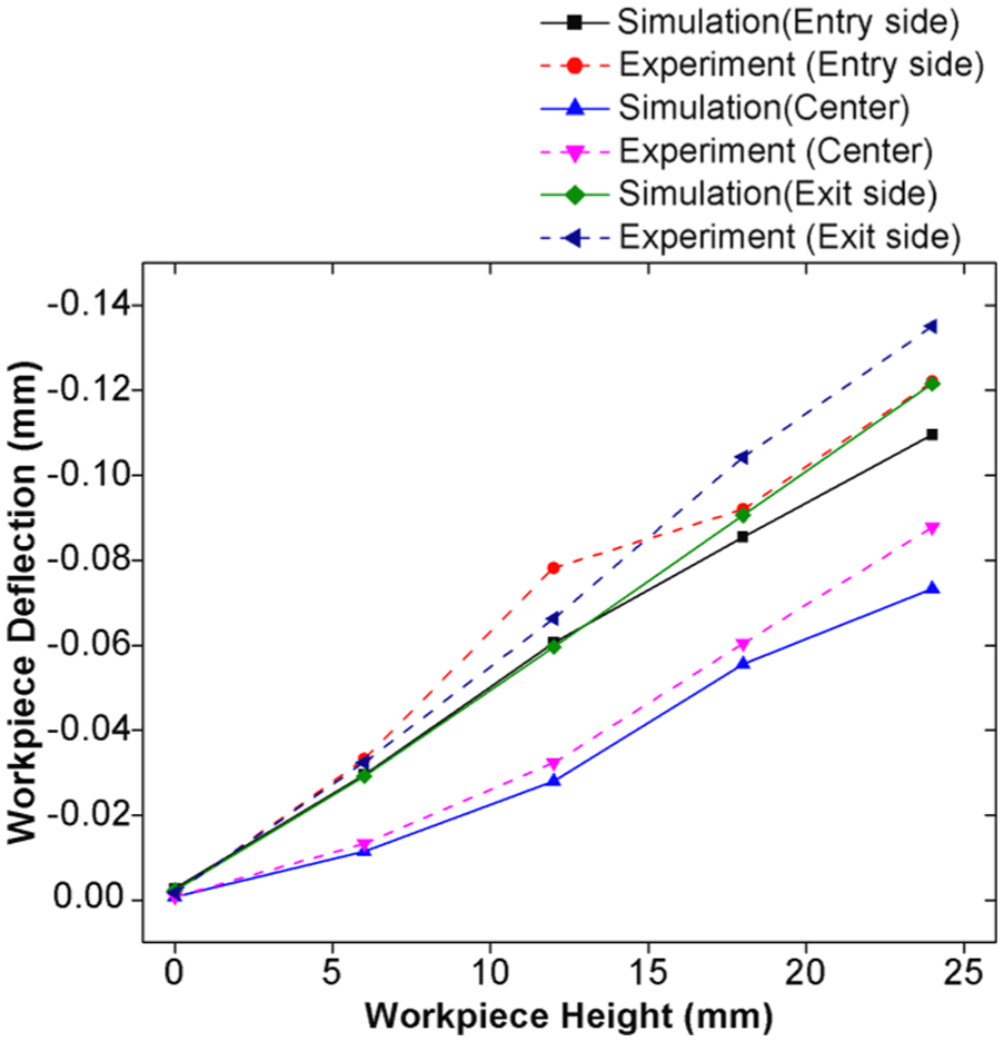
Comparison of numerical and experimental maximum deflection along the height of workpiece.
Figure 9 shows the side view of the machined workpiece obtained during numerical simulation and experimental work. It is noted that due to higher deflection occurring at top end during milling process, material remains uncut leading to thicker top edge compared to the base of workpiece.
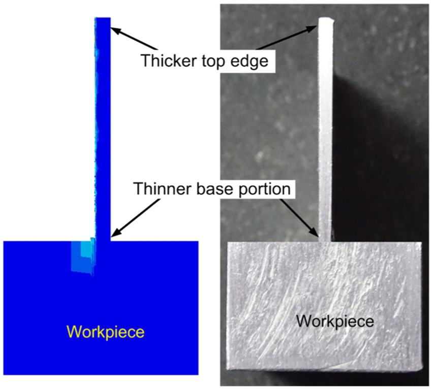
Comparison of form error obtained during numerical simulation and experiments.
Stress distribution
FEM-based simulation modeling has the advantage of predicting distribution of stresses during the machining process. Stress distribution during end milling of thin wall is shown in Figure 10. Stress during milling is found to be maximum at the primary deformation zone, where the tool and workpiece are in contact. Figure 10(a) shows the stress developed during the process and it can be observed that the stress is highly localized at the work–tool contact region near the cutting edge. The maximum induced stress at the milling area is around 700 MPa. Stress field gradually reduces away from the cutting zone. Also the residual stress contour in the machined surface at the end of the process is shown in Figure 10(b).
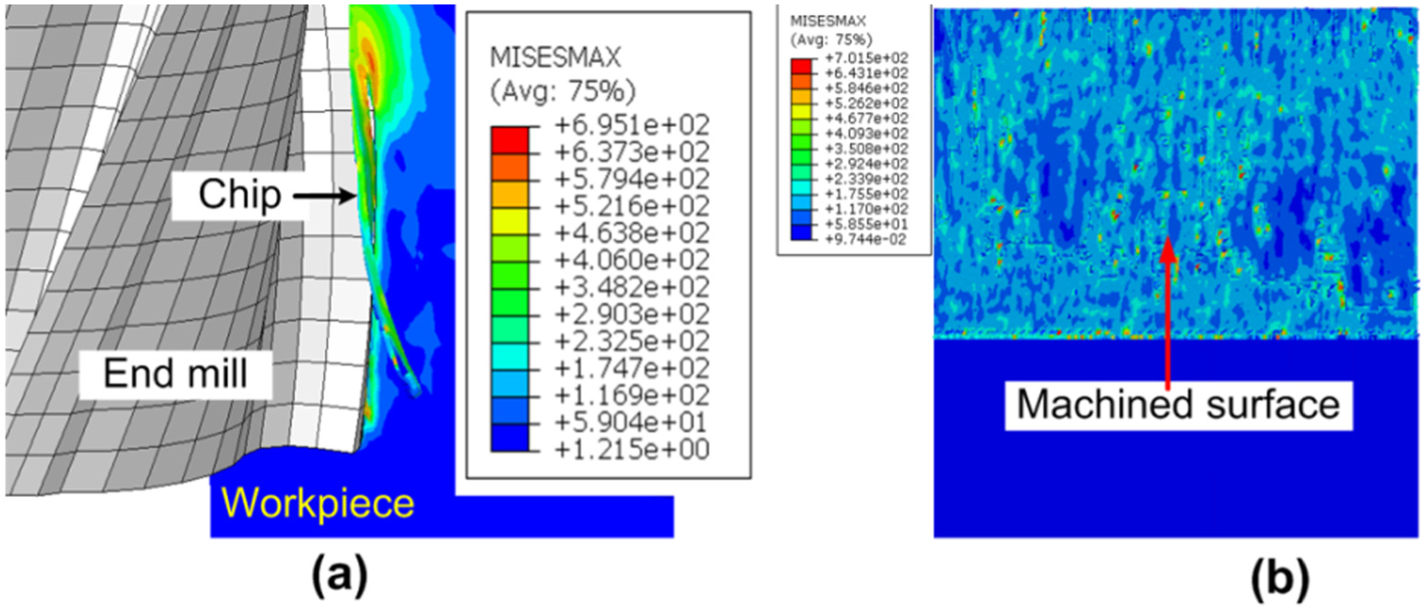
Stress distributions in thin-wall machining: (a) stress at cutting zone and (b) residual stress at the end of machining process.
Chip morphology
Surface roughness of machined surface depends on cutting parameters, tool characteristics and coolants used. Generally, chips formed during aluminum machining are of continuous type. These long chips have a tendency to curl back into the work surface. Many a times, curled chips degrade the machined surface quality and damage the cutting tool. 56 Other important characteristic associated with machining of aluminum is the formation of built-up edges (BUEs). The BUEs formed are harder than the work material and act as temporary cutting edges that adversely affect the work–tool interaction and thus result in poor surface quality. 57 Periodic fractures of BUE due to cyclic formation and disappearance lead to cutting instability which contributes to cutting vibration. 58 Therefore, it is very important to select proper cutting and tool-related parameters that help in obtaining the desired chip morphology and surface finish during aluminum alloy machining. In this work, the formation of chips due to the shear deformation is simulated using J-C damage model. Figure 11(a)–(d) illustrates the chip formation at four different time intervals in helical end milling process. Figure 11(a) depicts the initial cut as the tool enters the workpiece. As the tool applies pressure over the workpiece, chip separation from the workpiece is initiated. Figure 11(b) shows the flow of chip over the rake face. Figure 11(c) shows the curl of chip forms and it slides over the spiral tool flute. Figure 11(d) shows the chip about to detach from the workpiece.
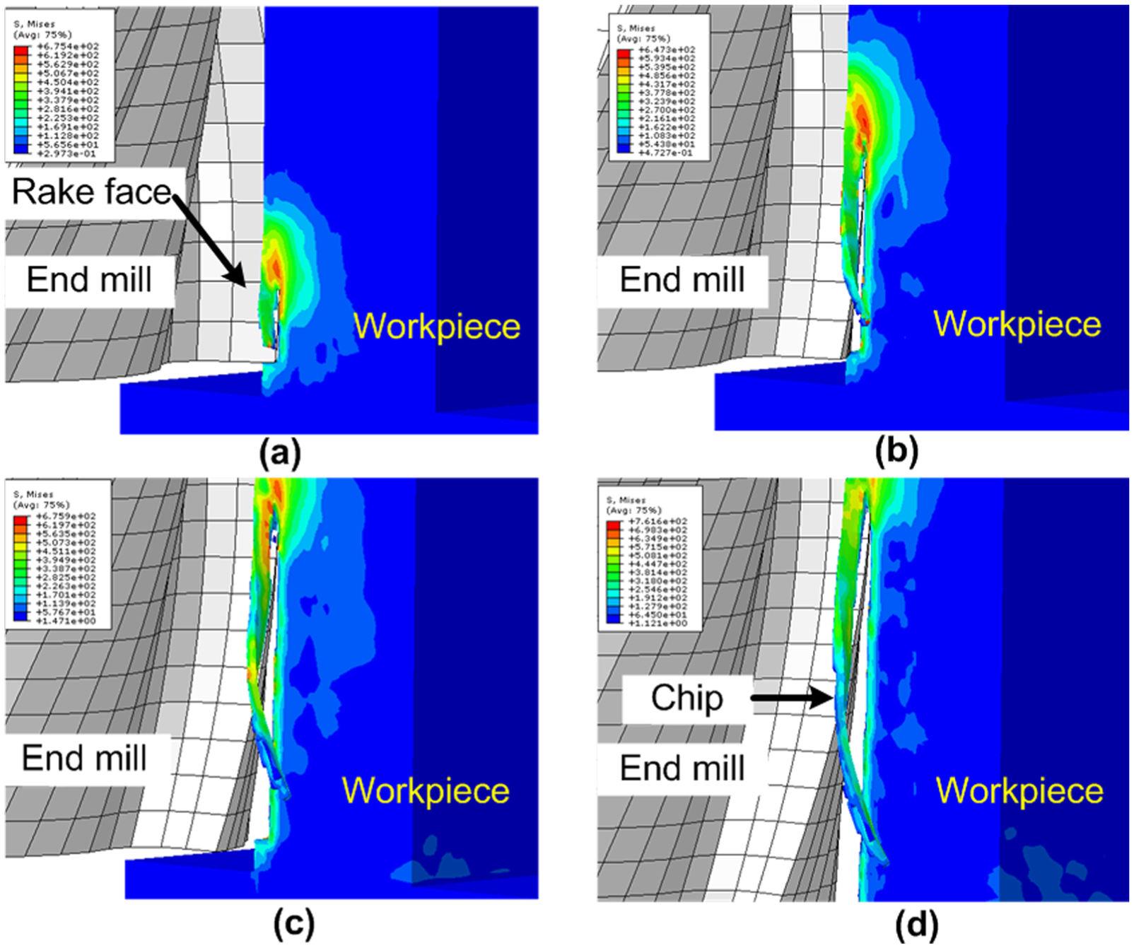
Chip evolution stages: (a) initial chip cut, (b) chip flow over rake face, (c) chip curling and (d) chip detachment.
Figure 12 shows the comparison between the morphology of a chip obtained in the numerical simulation and experiments. It is noted that the shape and size of the simulated chip are quite similar to that obtained in the experiments. Average values of chip width recorded during the experimental study and numerical simulation were around 680.52 and 773.8 μm, respectively. The chip has curled due to the influence of helical shape associated with the flute over which it slides during its formation. The work material flows around the cutting edge of the tool; therefore, the physical process was simulated more realistically.
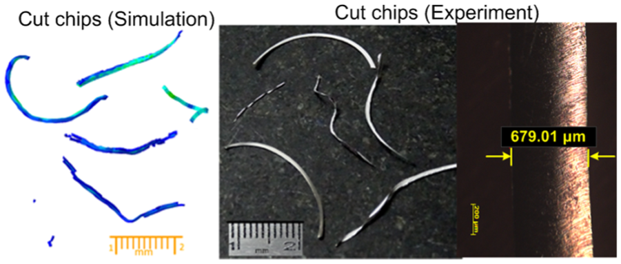
Comparison of chip morphology obtained by numerical simulation and experiments.
Temperature distribution
The transient temperature distribution is dynamically simulated during the thin-wall milling process. The cutting temperature plays an important role in metal cutting process as it affects tool wear and quality of the finished surface. In a machining process, the temperature rise is mainly attributed to the plastic deformation of work in the shear zone and frictional heat produced at chip–tool interface. Out of the total heat generated, a portion is dissipated into the surrounding environment by convection; however, the remaining portion gets transferred to the chip and tool through conduction mode of heat transfer. It is to be noted that during the machining of aluminum alloy, the heat dissipation to the environment is high due to the high thermal conductivity of the material. Figure 13 shows the plot for temperature rise during milling process. It is observed that as the machining commences, the temperature rises gradually due to the generation of heat in the process of plastic deformation. It increases with the time, attains its peak during the chip separation and then reduces when the chip detaches from the parent material. In this work, it was found that the simulation results are very well matching with that of the experimental studies with an average error of 17%. The trends of variations are also agreeing well.
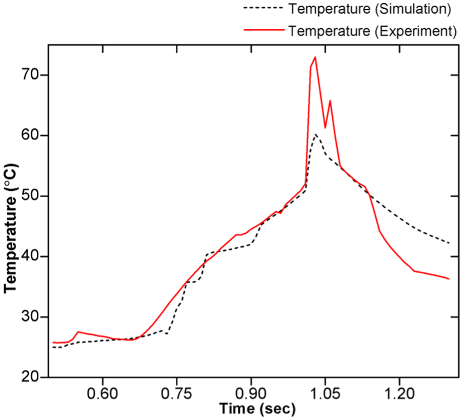
Comparison of temperature obtained by numerical simulation and experiments.
From this work, it can be seen that a 3D mathematical model and its successful simulation solves a quite complex problem of simulation of helical milling of thin-wall components. It helps in the prediction of important process performance parameters such as cutting forces, deformation, stresses, chip morphology and temperature quite accurately and easily. A prior knowledge about these parameters certainly helps the process engineers to tune up the process parameters to achieve the desired process performance. Predicted cutting forces provide an approximate estimation of energy requirement. Deformation values forecast the quality of the product in terms of the dimensional accuracy. Stresses will help in the estimation of the strength of the machined workpiece, while the chip morphology predicts the surface quality of the machined workpiece. Thus, it can be said that mathematical modeling and simulation provides a useful tool to the engineers and scientists to carry out a prior detail study of the cutting process.
Conclusion
In this work, a realistic 3D fully coupled thermal-stress FE-based mathematical model is developed to simulate the complex physical interaction of helical cutting tool and workpiece during thin-wall milling of aluminum alloy. The simulation results are verified by conducting milling experiments and the model is found to be predicting well the cutting forces, deformation, stresses, chip morphology and temperature at workpiece surface. Deflection occurring during the thin-wall machining process has been successfully simulated and it is noted that maximum deflections are occurring at the free end of the wall as compared to the center. It is also observed that due to the deflection of the wall, some materials at the base of the wall remain uncut that further leads to geometric form error in the workpiece. The simulated cut-chip of material has noted to have a similar curl as that occurs in physical experiments. Developed mathematical model provides an efficient tool to predict the important process performance parameters such as cutting forces, deformation, stresses, chip morphology and temperature for a prior study of the process. This eliminates the need of costly, tedious and time-consuming experiments. However, the present mathematical model can further be improved by incorporating the effect of material anisotropy and tool vibrations.
Footnotes
Declaration of conflicting interests
The author(s) declared no potential conflicts of interest with respect to the research, authorship and/or publication of this article.
Funding
The author(s) disclosed receipt of the following financial support for the research, authorship, and/or publication of this article: This work was supported by the Science and Engineering Research Board (SERB), Department of Science and Technology, Government of India (Grant number SR-S3-MERC-0115-2012).