
Abstract
The aim of this investigation is to identify the Al2O3-(W, Ti)C ceramic fracture modes and failure mechanisms under different cutting speeds and feed rates during intermittent turning of hardened 20CrMnTi steel. The failure surfaces of the cutting tools were examined by digital optical microscope and scanning electron microscope. The cutting forces and transient temperature in the intermittent turning process were measured during the entire life cycle. The experimental results showed that the cutting forces exhibited an increasing trend with the tool failure progression, which in turn accelerated the tool failure progression. The main failure modes of ceramic tools were wear and micro-chipping in the initial stage and final fractures, resulting from mechanical damage and thermal damage in intermittent turning processes. And the cutting temperature increased with the increase in cutting speed. The cutting speeds and feed rates were closely correlated with ceramic tool fracture modes and failure mechanisms. Furthermore, the combination of cutting parameters was divided into four regions with different fracture modes and failure mechanisms of cutting tools according to the fracture morphology of cutting tools. This partitioning analysis can provide a basis for the design and development of different ceramic cutting tools with the desired properties for different applications.
Introduction
Ceramic cutting tools have unique mechanical and chemical properties, especially at high temperature, such as high wear resistance, high hardness and relatively low chemical reactivity with steel and many other materials. 1 Moreover, for the Al2O3-based ceramic cutting tools, Al2O3 in a cutting tool can assist in reducing the adhesion of the workpiece material to the cutting tool surface.2,3 Al2O3-based ceramics are considered to be one of the most suitable tool materials for machining hardened steel.4,5 Many studies have been carried out in turning hardened steel, with the concentration on the contrast of tool life of different cutting tools.6,7 The results of intermittent turning of hardened AISI 1045 steel revealed that Al2O3-based ceramic cutting tools were more suitable tool materials for intermittently turning hardened steel than cemented carbide tools. 7 On the other hand, the Al2O3-based ceramic cutting tools can produce good surface finish in the machining of hardened steel. 8
An understanding of the failure mechanisms is a prerequisite for proper usage of these tools and the development of new tools. Grzesik and Zalisz 9 reported that wear mechanisms observed in dry and hard turning process were abrasion, fracture, plastic flow, adhesive and tribo-chemical wears depending mainly on the thermal and mechanical conditions generated on the wear zones. Usually, the failure of a cutting tool was an intricate phenomenon and a result of interaction of the above several failure mechanisms. 10 Similarly, the failure modes of poly-crystalline diamond (PCD) cutting tools during core drilling of reinforced concrete were classified as chipping, gross fracturing and delamination. Then the fracture mechanisms were generally classed as brittle crack propagation and fatigue crack growth. 11 It was also reported that cutting edge chipping and flaking were mainly caused by the micro-crack growth in ceramic tools. 12 A change in cutting condition especially in the cutting temperature would lead to the transition in main effect of the failure mechanism.
The failure mechanisms of some cutting tools have been studied in an intermittent cutting process.13 –18 The combined effect of thermal stress and mechanical stress contributed to the tool chipping, flaking, micro-crack propagation, abrasion and adhesion for the ceramic tools in the ultra-high-speed milling.15,16 Mechanisms of cracks’ formation under different conditions and their effects on wear and fracture resistance of ceramic tool materials were researched. 18 Furthermore, a lot of researches were made on thermal fatigue of ceramic and cemented carbide cutting tools in interrupted cutting operations.19 –21 Severe temperature gradients and thermal stress gradients in the interior of the cutting tool might lead to thermal cracks in the cutting edge under cyclic thermal shock in an intermittent cutting process. 7 Under high cutting speeds, thermal damage was the major cause of tool failure. Thermal cracks usually initiate at the tool–chip interface (about 0.1–0.3 mm from the cutting edge) and propagate toward the cutting tool substrate. 22 Some authors explained that these cracks were promoted by the repeated expansion and contraction of the surface layers of cutting tools when they were cyclically heated in the cutting process and cooled in idle periods of intermittent cutting.19,20 When relatively high cutting speeds are adopted, retention of the mechanical properties to high cutting temperature and resistance to thermal impact were priorities for the increase in the tools’ life. 23
In summary, it should be noted that the prevailing percentage of previous research focused on the wear behavior of Al2O3-based cutting tools in a continuous cutting process, as well as some researches about failure mechanisms of ceramic tools in an intermittent cutting. But there is marginal amount on the exact relation between the characteristic failure modes and the cutting parameters for Al2O3-based cutting tools, as well as the proportion of thermal and mechanical damage to tool failure under different cutting parameters in an intermittent cutting. The failure modes and failure mechanisms were significantly correlated with cutting speeds and feed rates. So the typical failure modes and failure mechanisms under different cutting speeds and feed rates were qualitatively distinguished based on a series of intermittent turning experimental observations. This partitioning analysis could provide a basis for the design and development of different ceramic cutting tools with the desired properties for different applications. The users can formulate the corresponding measures to prolong ceramic cutting tool life and improve machining efficiency as a profitable alternative to finish grinding.
Experimental investigation
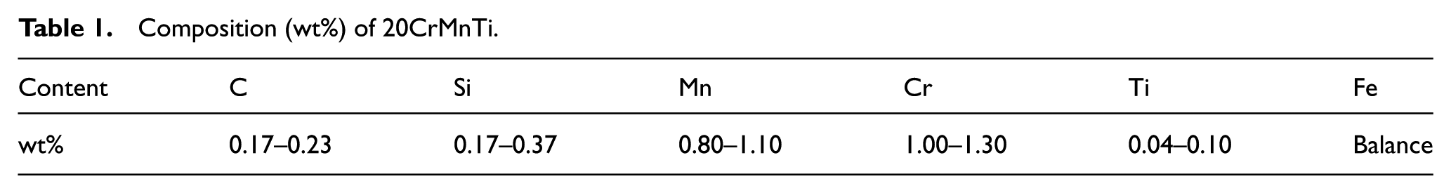
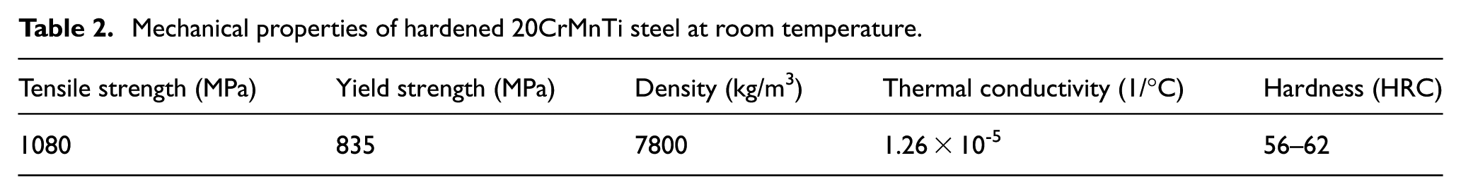
The hardened material selected for intermittent turning was commercially available gear shaft material (20CrMnTi, face hardened 58–62 HRC). The depth of hardening layer of the workpiece material was about 1 mm. The composition (wt%) and the mechanical properties of this material are presented in Tables 1 and 2, respectively. The mechanical properties of hardened 20CrMnTi steel at room temperature were from the national standard GB/T 3077-1999. The workpiece material was in the form of narrow plates with a thickness of 16 mm, four of which were clamped in the four peripherally distributed straight slots of a cylindrical fixture by screws as shown in Figure 1(b). The insert undertook four times of impact per revolution. And the ratio of the cutting length to air cutting length was about 0.193. Each experiment was replicated until the steady experiment data were achieved for every cutting condition. The cutting forces were measured using Kistler piezoelectric dynamometer (type 9265A) mounted on the machine table as shown in Figure 1(a). The charge generated at the dynamometer was amplified using a multichannel charge amplifier. The outputs of force sensor were filtered to eliminate high-frequency noise induced by the process variables. The cutting temperature was measured by handheld infrared thermal imager (NEC Sanei Co. Ltd, Tokyo) in the distance of about 0.5 m from the measured point. The infrared beam focused on the cutting area. To reduce measure error, an average of five maximum temperatures was adopted as the cutting temperature.
Composition (wt%) of 20CrMnTi.
Mechanical properties of hardened 20CrMnTi steel at room temperature.
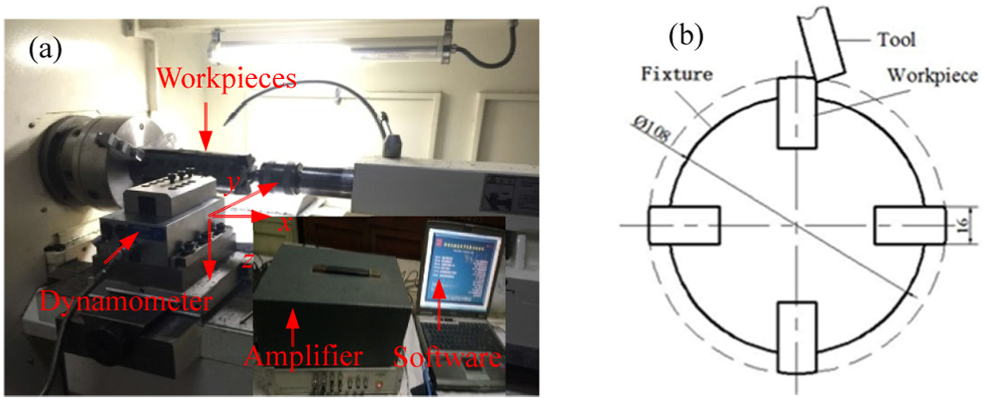
(a) Layout of the experimental apparatus and (b) schematic illustration of workpieces and fixture geometry in intermittent turning experiments.
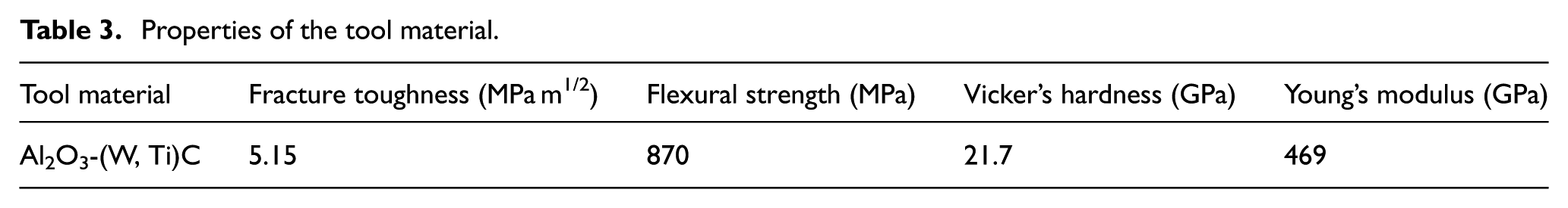
An Al2O3-(W, Ti)C composite ceramic tool was used in the experiments. The properties of the tool are shown in Table 3. The cutting tools have 0.3 mm tool nose radius and chamfering width br1 = 0.1 mm. The cutter arbor has the following geometries: rake angle γ0 = -6°, clearance angle α0 = 6°, inclination angle λs = -6° and cutting edge angle kr = 75°. The intermittent turning tests were conducted on a CKD6150H computerized numerical control (CNC) lathe under dry condition to avoid severe thermal shock to ceramic tools. Currently, the cutting parameters of ceramic cutting tool were mainly recommended for continuous cutting. The range of the cutting parameters in the intermittent cutting was selected according to our previous studies.7,17 The cutting parameters of the intermittent turning tests in the form of single factor are listed in Table 4.
Properties of the tool material.
Cutting parameters.

The experiments were paused at regular intervals of 20 mm cutting length. Evolution of the tool failures was obtained by periodically observing the value of tool wear with an optical microscope during the cutting tests. It was reported that tool nose wear, chipping or instantaneous fracture of the cutting edge were dominant failure modes of ceramic tools in an intermittent turning process.7,12 Therefore, the tool rejection criteria were employed and the following values were considered for tool life testing:
Maximum flank wear > 0.6 mm.
Macro-chipping (flaking) or fracture of the cutting edge.
After the intermittent turning experiments were finished, a scanning electron microscope (SEM) (Hitachi S-570, Japan) equipped with type JED-2300 energy-dispersive spectroscopy (EDS) was used to examine the nature of the worn or fractured tools. Three-dimensional (3D) topography was examined with a VHX-600E optical microscope (KEYENCE Co., Japan).
Experimental results and discussion
Effect of cutting parameters on tool life
The results obtained from the intermittent turning experiments showed that the tool wear increased slowly in the initial stage under low cutting speeds and feed rates, while under high cutting speeds and feed rates, the tool wear increased quickly in the initial stage. The final failure mode was excessive chipping (flaking) or catastrophic fracture. In addition, the experimental results showed that the cutting speed had more effect on the tool life than the feed rate.
Cutting speed
Figure 2(a) shows the progression of maximum flank wear with an increase in the impact number at f = 0.1 mm/r. The tool life decreased with an increase in cutting speed at f = 0.1 mm/r. And the longest tool life was obtained at v c = 70 m/min, f = 0.1 mm/r and a p = 0.1 mm. It was obvious that the increase in the cutting speed accelerated the progression of tool damage. Figure 2(b) shows the progression of maximum flank wear versus tool life at f = 0.25 mm/r. The life of ceramic cutting tool is not only related to the cutting parameters but also related to the cutting tool material microstructure shown in Figure 3. Ceramic tool material is composed of grains with irregular shapes, and the mechanical properties of different points are different. In our experiments, the longest tool life was obtained at the cutting speed of 150 m/min, which might be explained as follows: in the cutting process, the maximum cutting temperature increased with the increasing cutting speed; as the cutting speed increased from 70 to 150 m/min, the workpiece was softened with the increasing temperature, consequently the shear strength of the workpiece and the friction coefficient at the tool–chip interface decreased, which probably resulted in an increased tool life.24,25 While with the increasing cutting speed above 150 m/min, the cutting temperature was very higher, which lead to high adhesions on the tool rake surface; in turn, the excess adhesions introduced the higher cutting temperature, which decreased the tool strength; on the other hand, the high thermal stresses in the cutting edge also reduced the tool life.20,26 On the whole, the maximum flank wear of the cutting tool increased gradually in the initial stage of cutting. With the increase in the cutting time, the failure mode transformed from wear and micro-chipping to chipping in a large-scale or catastrophic fracture in the final stage.
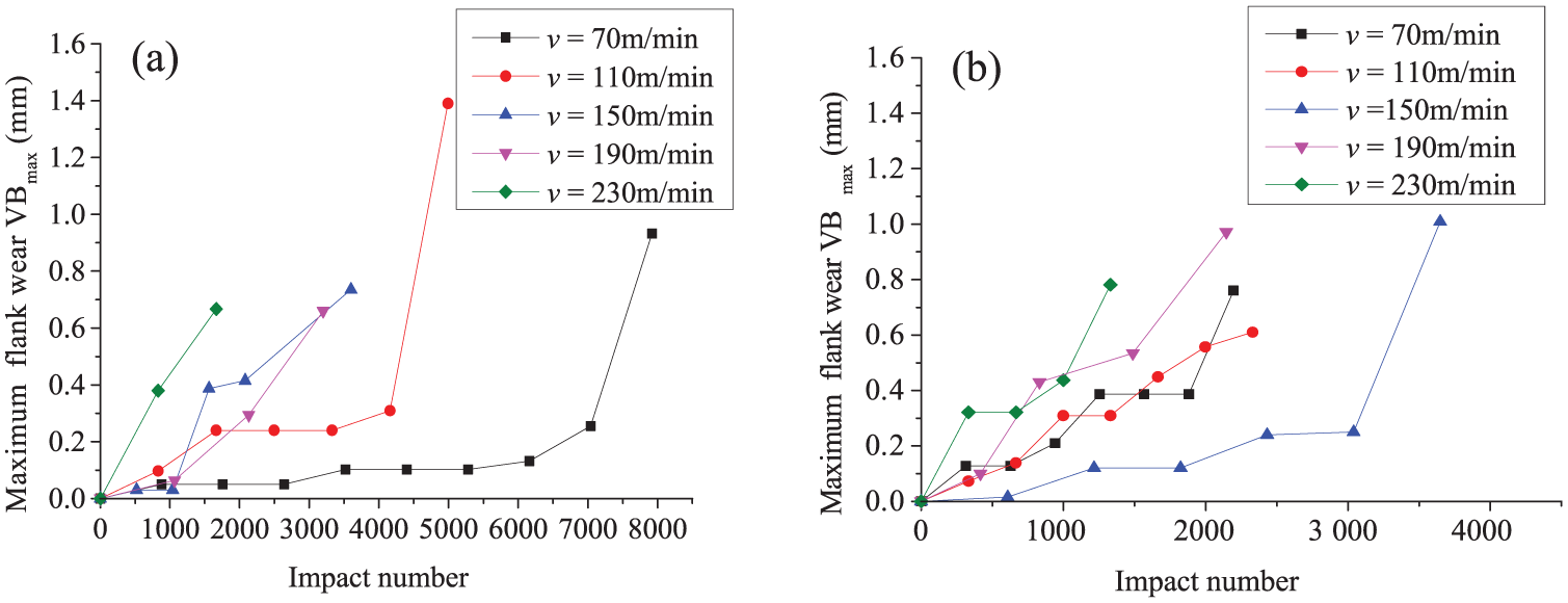
Progression of maximum flank wear versus impact number (a p = 0.1 mm): (a) f = 0.1 mm/r and (b) f = 0.25 mm/r.
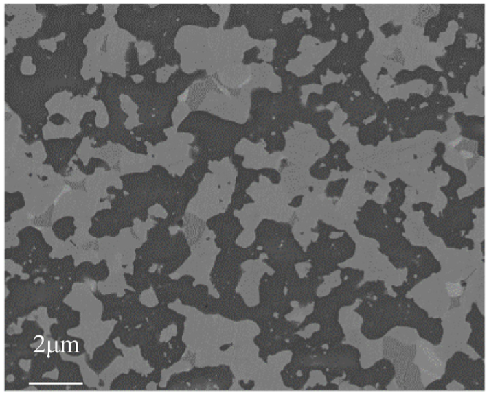
Microstructure of polished tool surface.
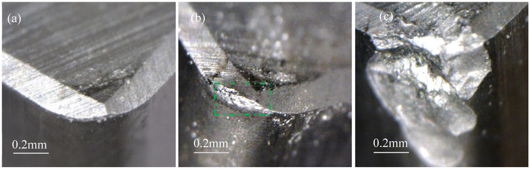
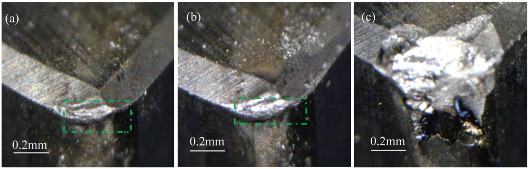
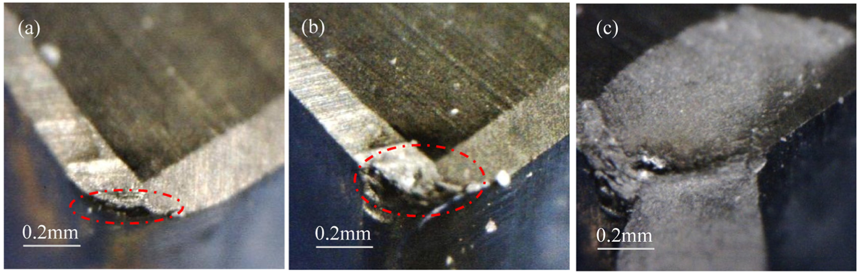
Figures 4–6 present the failure images of the tool noses under cutting speeds from 70 to 230 m/min at the different stages of the cutting process. The ceramic tools experienced wear around tool nose (marked with a rectangle in Figures 4(b), 5(a), (b) and 6(a), (b)), as well as slight chipping (marked with oval outline in Figure 6(a) and (b)) in the normal cutting stage. Since the chipping area and thickness are very small, the tool could still be used for cutting. Damage of the tool material was accumulated at the tool nose mainly and it was inferred that micro-cracks would appear and extend with the increase in the impact number according to previous research.7,18 With the increase in the number of cutting impacts, the cracks propagated fast, leading to fracture and flaking of the cutting tool, and then the cutting tool was out of work (Figures 4(c), 5(c) and 6(c)). Ultimately, the failure mode of ceramic tools was mainly characterized by breakage rather than wear. This phenomenon was also observed by Jaharah et al. 27 In their studies, brittle fracture was attributed to the early formation of a crack in an area of high-stress concentration, in particular, at the nose of the cutting tool. It can be inferred that the failure of ceramic tools was caused by the mechanical fatigue crack extension under the cutting speed of 70–150 m/min. However, the increase in cutting speed from 190 to 230 m/min lead to severe rubbing action between the tools and the workpieces, and thus generated more heat, even though contact time decreased. Thermal damage increased and became the major cause of tool failure when the cutting speed was higher than 190 m/min. And the damages of the tool’ material were accumulated; the mechanical shock prompted the tool’ material to be peeled off at the tool–chip interface region mainly soon. At higher cutting speed, thermal damage and mechanical damage competed against each other. And fracture in the tool–chip interface region was observed (Figure 6(c)). It could be inferred that the tool life of ceramic tool was mainly controlled by the thermal damage. The cutting speed had a strong effect on tools’ failure when the cutting speed exceeded 190 m/min.
Failure morphology of ceramic insert (v = 70 m/min, a p = 0.1 mm, f = 0.1 mm/r): (a) after impact number of 880, (b) after impact number of 7040 and (c) after impact number of 7920.
Failure morphology of ceramic insert (v = 150 m/min, a p = 0.1 mm, f = 0.15 mm/r): (a) after impact number of 1227, (b) after impact number of 1840 and (c) after impact number of 2453.
Failure morphology of ceramic insert (v = 230 m/min, a p = 0.1 mm, f = 0.15 mm/r): (a) after impact number of 550, (b) after impact number of 1109 and (c) after impact number of 1664.
Feed rate
Figure 7(a) shows the tool wear progression with the increase in the impact number for the ceramic tools at different feed rates and the cutting speed of 70 m/min. The ceramic tools had a longer stable wear stage and possessed better wear resistance in the feed rate of 0.1–0.15 mm/rev. However, the tool wear increased quickly in the feed rate of 0.2–0.3 mm/rev at the beginning of cutting, and the impact number was less than 4000. The change in the tool wear progression with the increase in feed rates was not remarkable when the cutting speed was 190 m/min. On the whole, higher feed rates caused an increase in material removal rate, while tool life decreased. The reason is that the temperature increased, and the stress generated on the rake and flank faces close to the nose probably caused the reduction in yield strength of the tool. 28 It is difficult to define clearly the influence of the feed rate on the tool wear, and many factors shall be considered. The factors include the cutting time, the cutting temperature, the uncut chip thickness, the normal contact stress at the tool–chip interface and the intensity of the machining vibrations.29,30 The tool wear at high feed rates was mainly due to the high cutting forces and, in turn, severe damage. When the maximum flank wear of the cutting tool was beyond about 200 μm, the fluctuant load caused fractures of the cutting edge and lead to a rapid increase in maximum flank wear or fracture. This phenomenon was also observed by Tamizharasan et al. 31
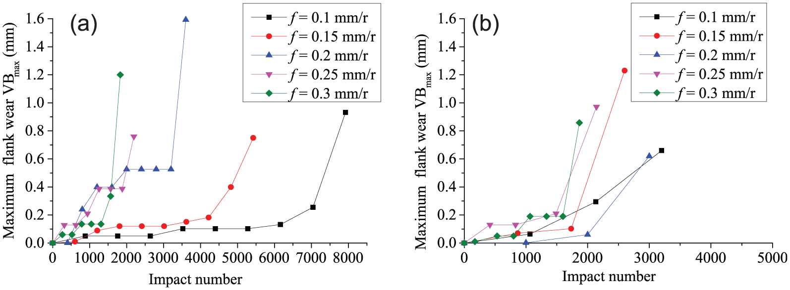
Progression of maximum flank wear versus impact number (a p = 0.1 mm): (a) v = 70 m/min and (b) v = 190 m/min.
Effect of cutting parameters on cutting force and cutting temperature
Cutting force
Figure 8 shows the evolution of the experimental cutting forces in three directions measured using a Kistler piezoelectric dynamometer under the cutting condition of v = 70 m/min, f = 0.1 mm/r and a p = 0.1 mm. The impact forces in the tool entry and tool exit were more than two times the average cutting forces. Due to unstable impact forces when the tool entered and exited the workpiece, the average cutting forces were used to analyze the variation trends of the cutting forces with cutting speeds and feed rates.
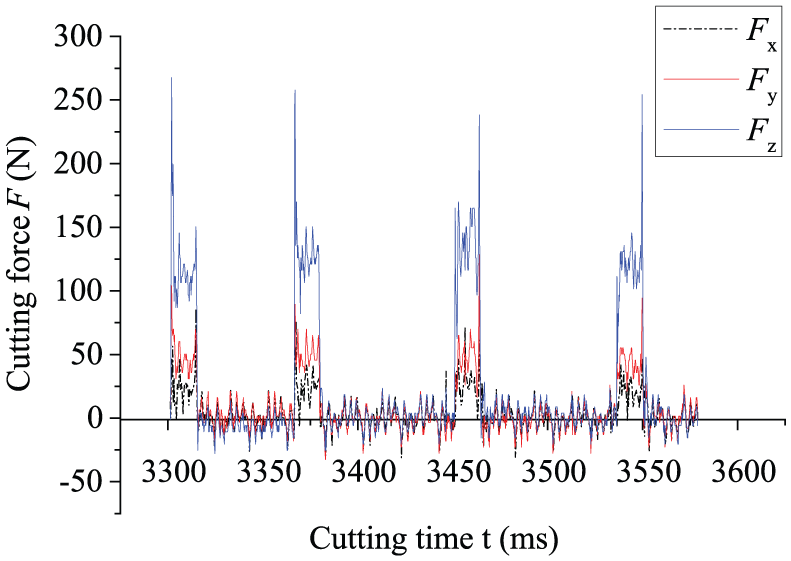
Experimental cutting forces (F x, F y, F z) at the cutting speed of 70 m/min (a p = 0.1 mm, f = 0.1 mm/r).
The tool life in the cutting test is represented by the impact number N t from 1430 to 7920. To highlight the different stages of tool service life or the states of tool wear, the normalized life of the range of 0–1 is introduced. The normalized life is defined as N or = N i/N t, where N i means the cumulative number of the impact that the tool has born when the experiments are paused at regular intervals, and N t means the total number of the impact that the tool has born prior to failure. When N or = 1, the cutting tools fail and have born the total impact number N t. Figures 9 and 10 clearly illustrate the average cutting forces versus the normalized life under the different cutting parameters. The comparisons of the average cutting forces under different feed rates at v = 70 m/min and a p = 0.1 mm are shown in Figure 9. With the increase in the cutting time and the progression of tool wear, the cutting forces measured under each cutting parameter combination show an overall tendency to increase. And the cutting force increased with the increase in feed rate at the stable cutting stage. The increase in feed rate enhanced metal removal rate, thereby increasing the cutting force (Fz ) and the work done during the cutting process. The comparisons of the average cutting forces under different feed rates at v = 230 m/min and a p = 0.1 mm are shown in Figure 10. The cutting forces increased significantly with the increase in feed rates at the initial cutting stage due to more intensive mechanical impacts on the tool edge. Furthermore, the average cutting forces increased with the increase in the tool wear.
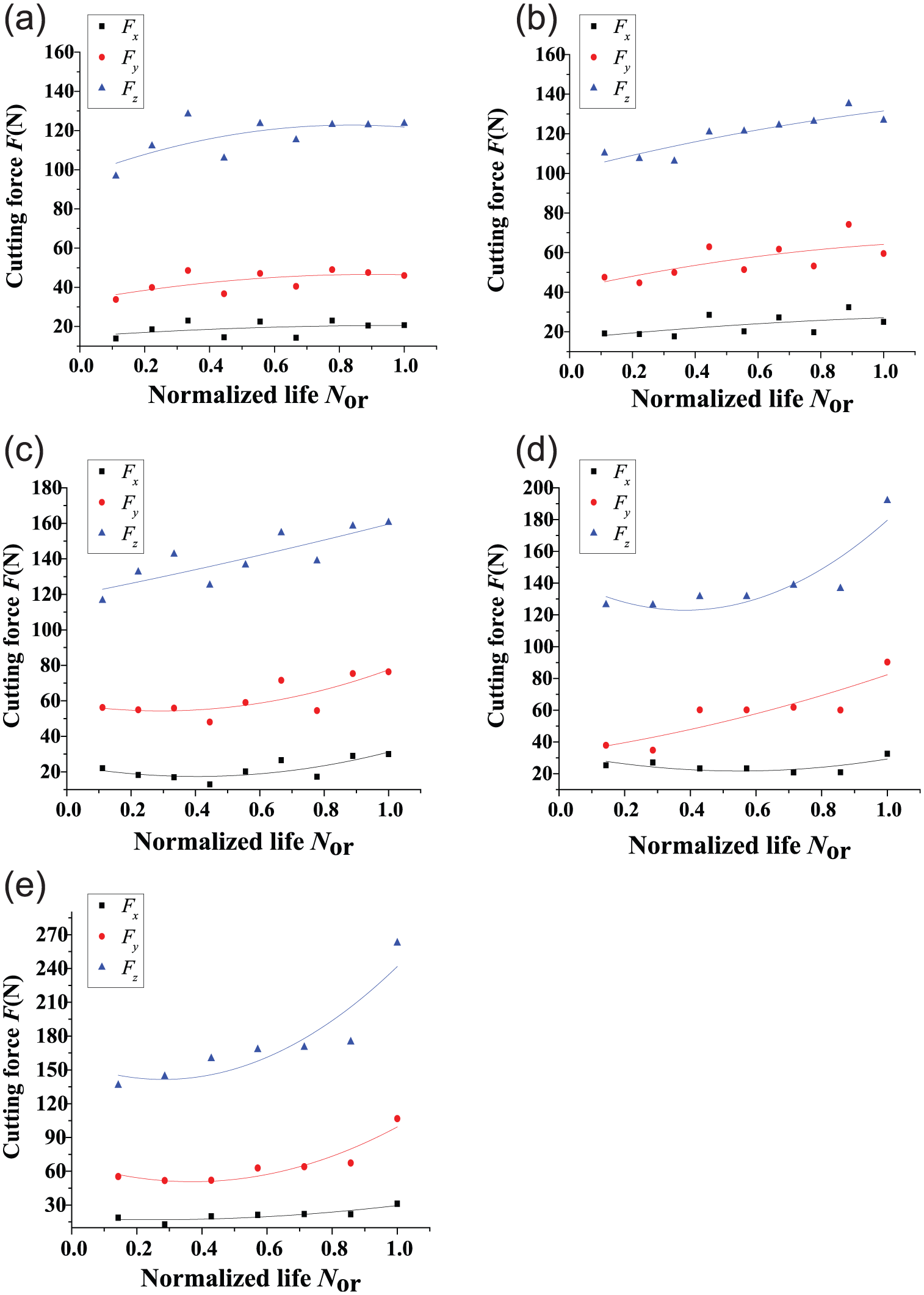
Cutting forces versus normalized life at v = 70 m/min and a p = 0.1 mm: (a) f = 0.1 mm/r, (b) f = 0.15 mm/r, (c) f = 0.2 mm/r, (d) f = 0.25 mm/r and (e) f = 0.3 mm/r.
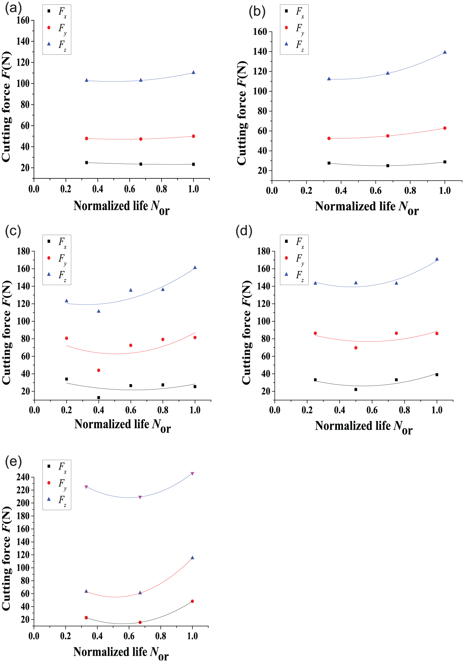
Cutting forces versus normalized life at v = 230 m/min and a p = 0.1 mm: (a) f = 0.1 mm/r, (b) f = 0.15 mm/r, (c) f = 0.2 mm/r, (d) f = 0.25 mm/r and (e) f = 0.3 mm/r.
Figures 9 and 10 compare the average cutting force components Fx , Fy and Fz under different cutting speeds. It is evident that the average cutting forces Fz have little change with the increase in cutting speeds in the initial cutting stage when feed rates are less than 0.25 mm/r. Similar results have also been reported in interrupted machining of Ti6Al4V. 32 The variation in the cutting force components might be related to a number of factors, such as the work hardening of the workpiece material, the degree of the tool wear, the thermal deformation of the workpiece and cutting tool as well as machine tool vibration.28,33
Cutting temperature
Figure 11(a) shows the temperature map measured by thermal infrared imager. The separated chips accumulated together. The cutting temperature referred to the maximum temperature in the cutting region. According to Li et al., 29 as the surface of the hardened steel was not covered by oxide layer, the thermal emissivity of the hardened steel could be determined as 0.30 for the temperature range of 150 °C–1000 °C. Many factors may cause a fairly large scatter of the temperature readings. The factors include dust accumulation on the measuring face of the tool insert, flying chips and particles entering the vision field of an infrared thermal imager.
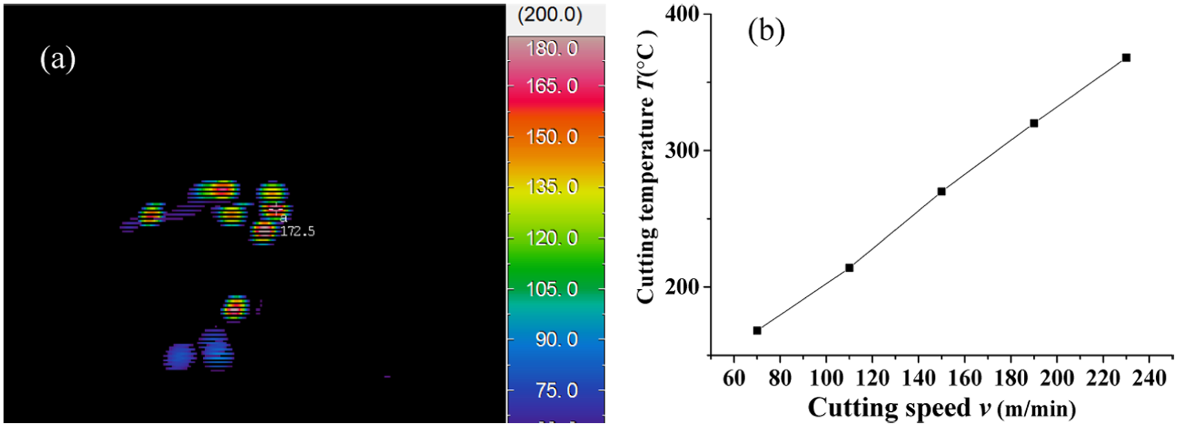
Cutting temperature T measured at f = 0.1 mm/r and ap = 0.1 mm: (a) infrared thermogram at v = 70 m/min and (b) cutting temperature T versus cutting speed v.
Figure 11(b) shows the effect of the cutting speed on the cutting temperature. At v = 70 m/min, the average infrared temperature was 168 °C in the intermittent turning experiment. At the cutting speed of 230 m/min, the infrared temperature reached 368 °C. The maximum cutting temperatures increased significantly with the increase in cutting speeds. Therefore, the thermal shock became the main factor of tool failure at the high cutting speeds. It was reported that thermal damage to the tools’ material increased in proportion to mechanical damage as a result of the increasing cutting temperature in high-speed intermittent cutting process.7,34
Tool failure analysis
Tool failure modes and failure mechanisms
Figure 12 shows the SEM images of the worn ceramic inserts when intermittent cutting hardened 20CrMnTi steel with ceramic tools under dry cutting condition at the cutting speed of 70 m/min. Wear and brittle fractures (chipping, cracking and flaking) can be observed. There are clear evidences for cracking, adhesion, flaking or spalling of individual or small clusters of grains. The mechanical fatigue cracks parallel to the cutting edge are seen in Figure 12(c) and (d). It was referred that cracks initiated at the tool nose and subsequently propagated, and then chipping in the large scale appeared around the tool nose. Mohajerani and Spelt 35 investigated chipping in brittle materials under impact loads. Repeated impact tests showed that crack growth was an important mechanism of chip formation. Micro-cracks caused by the initial impacts were extended by subsequent impacts until a chip was finally removed. The EDS chemical composition analysis on the fracture surface (point A in Figure 12(b)) is illustrated in Figure 12(e). A lot of Fe, Mn and Cr elements were identified in the cutting edge, while the ceramic cutting tool contained no Fe, Mn and Cr elements. So the Fe, Mn and Cr elements were adhered from the workpiece material 20CrMnTi and attached to the broke cutting edge.
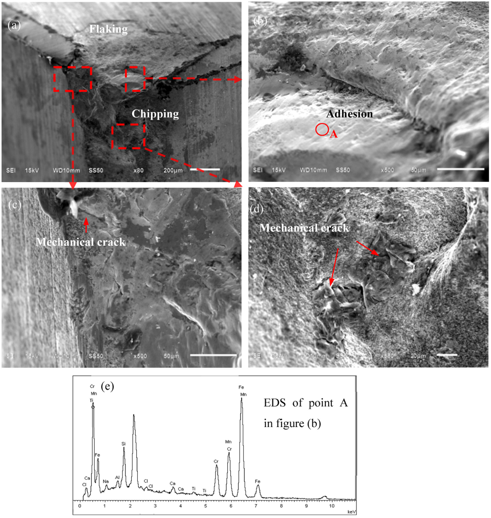
SEM images of ceramic tools in intermittent turning of hardened 20CrMnTi steel (v = 70 m/min).
When the cutting speed increases to 190 m/min, the fracture at the rake face is clearly observed, as shown in Figure 13. And the fracture occurred in the tool–chip interface region where the mechanical properties of ceramic tool material degraded with the increase in temperature. Thermal cracks perpendicular to the cutting edge appeared and the cracks extended nearer to the cutting edge of ceramic tools at relatively higher speeds in the previous research. 20 Although a set of cracks perpendicular to the cutting edge could not be seen in our experiment, thermal damage still existed. The mechanical shock prompted the tool edge to fracture due to performance degradation of tool surface material at relatively higher cutting temperature. So a small crack in Figure 13(b) was caused by a combined action of the thermal and mechanical loads. Some mechanical cracks as shown in Figure 13(c) which are nearly parallel to the main cutting edge are observed in the fractured tool nose. The most important factors which contributed to fracture in the tool–chip interface are the tool–chip interface temperature, interface pressure and sliding velocity between the tool and workpiece materials. Similar failure modes have been previously reported when machining hardened AISI 1045 steel using ceramic tools. 7 It is seen from Figure 13(d) that the fracture surface of ceramic tool is characterized by the typical intergranular fracture with candy-like particles. Brandt 20 reported that as long as the conditions were severe enough to cause thermal cracking in the cutting process, superficial plastic deformation (∼1 μm deep) and creep deformation appeared at the worn ceramic tool surface. Thermal damage of the tool surface material in the tool–chip interface region played a main role to tool failure under high cutting speeds. 19
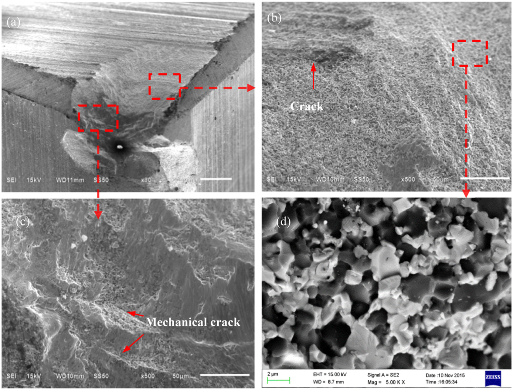
SEM images of ceramic tools in intermittent turning of hardened 20CrMnTi steel (v = 190 m/min).
Figure 14 shows the SEM images of worn ceramic tool in the intermittent cutting tests at the cutting speed of 230 m/min. The thermal cracks as shown in Figure 14(b) and (c) were seen in the fracture surface. The failure of cutting tools was caused by the interaction between mechanical and thermal damage. The failed surface shows a fatigue crack nucleation region located at the tool nose (region A in Figure 14(c)). Crack growth zones are classified into two distinguishable zones. One is the slow crack growth (SCG) zone (region B in Figure 14(c)) with a rough fracture surface characterized by radial stripes and the other is the transient-fracture zone (region C in Figure 14(a)) with a smooth fracture face. Furthermore, damage mainly occurred within the scope of approximately 0.15 mm below the tool surface. The tool failure was related to many factors such as the microstructural characteristics and thermomechanical properties of tool materials. It was very difficult to quantify the contribution of thermal and mechanical loads to tool failures in an intermittent cutting process. 7
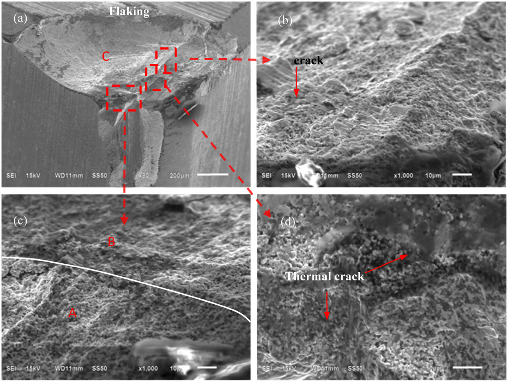
SEM images of ceramic tools in intermittent turning of hardened 20CrMnTi steel (v = 230 m/min).
Partitioning analysis of tool failure mechanisms
On the whole, the ceramic tools were subjected to high cyclic thermal–mechanical impacts in intermittent turning of hardened 20CrMnTi steel, and the fracture modes of cutting tools were relatively complicated. The fracture modes of cutting tools were affected by not only cutting speeds and feed rates but also cutting time. The failure mechanisms changed with the location of failure area, which might be in the tool nose and flank face or rake face and so on. And the cutting conditions such as cutting speeds and feed rates (or forces and temperature) could lead to the transition in the predominant failure mechanism. But the main characteristics of failure modes and failure mechanisms of cutting tools should be sought out under different cutting parameters. It would provide theoretical basis for tools’ design to increase the tools’ life.
Based on the previous results and discussions, the tool fracture modes and failure mechanisms under different cutting speeds and feed rates can be summarized in Figure 15. The critical line A distinguishes the main failure mechanisms of thermal damage from mechanical damage, and the critical line B distinguishes the influence degree of mechanical impact on tools’ fracture in a certain range of cutting speeds and feed rates. According to mechanical (or thermal) cracks and the fracture morphology of cutting tools, lines A and B in Figure 15 divide a combination of cutting parameters into four regions with different fracture modes and failure mechanism of cutting tools. The failure mechanisms of every zone are shown in Table 5. Two main failure mechanisms are qualitatively identified in Figure 15: mechanical and thermal damage. Mechanical damage basically existed under different cutting speeds and feed rates. Then thermal damage was mainly dependent on the cutting speed. The cutting temperature was a dominant factor influencing the proportion of thermal damage on the tools. The critical speed of thermal damage was 190 m/min under the current cutting conditions. Thermal damages in the form of thermal diffusion, thermal cracking and chemical reaction caused thermomechanical properties of tool materials to be weakened so that mechanical impact or adhesion could more easily break cutting tools.
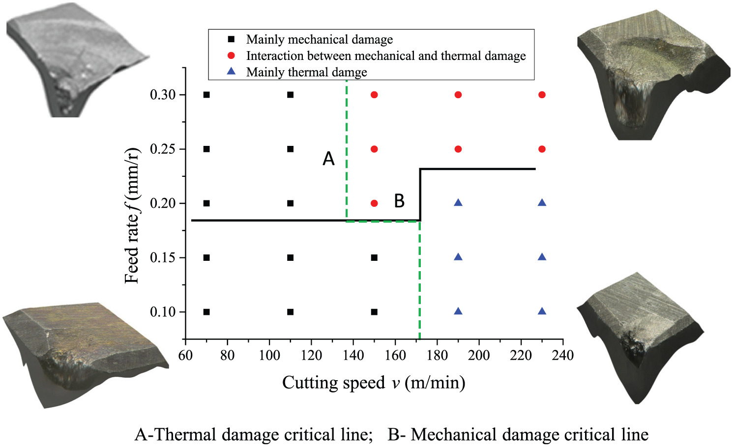
Ceramic cutting tool failure analysis diagram.
The main failure mechanisms in the different zones.
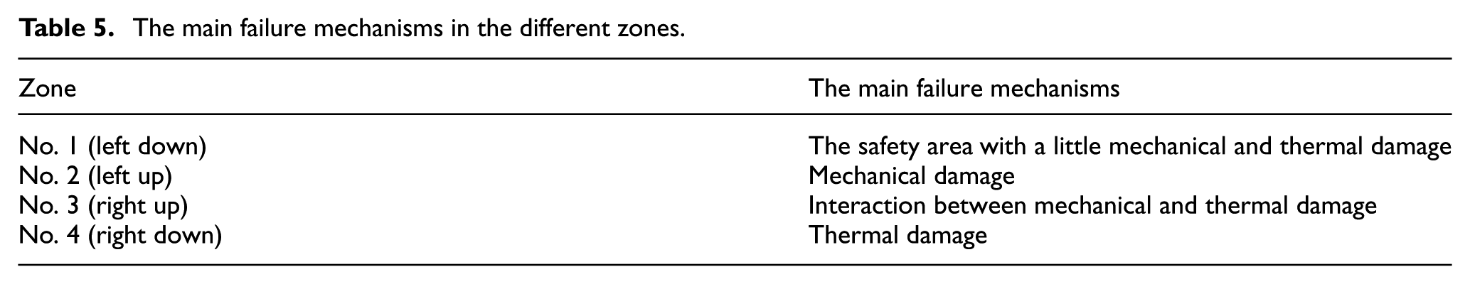
When the cutting speeds and feed rates were relatively lower (Figure 15, left down), tool nose fractured in a small scale because when small mechanical shock energy transferred from the tool nose to the substrate, shock energy decreased quickly, and meanwhile, the cutting temperatures were too small to make the mechanics performance of the cutting tool material degrade. The 3D surface topography of typical worn tools taken by a VHX-600E optical microscope (KEYENCE Co.) is shown in the corresponding position of every zone in Figure 15. And while the cutting speeds were relatively lower and the feed rates were relatively higher (Figure 15, left up), the mechanical loads became large and the breakage degree of the tool increased and the worn tool was characterized by the fan-shaped fracture in the rake face or sometimes chipping in the flank face due to the mechanical damage. The effect of mechanical impact increased with the increase in feed rates. But when the cutting speeds and feed rates were relatively higher (Figure 15, right up), the interaction between mechanical and thermal loads accelerated the forming and expanding of the crack. Due to severe working conditions, the failure modes of ceramic tools in No. 3 zone were fractures of the rake face and flank face in a big scale. Except macro-chipping in the flank face, the worn tools were characterized by the fan-shaped failure morphology in the rake face due to the mechanical shock loads. At a relatively higher cutting speed and a relatively lower feed rate (Figure 15, right down), the worn tools were mainly identified as fracture of rake face in the tool–chip interface region (Figure 15, right down). The alternating appearance of cutting and non-cutting periods in interrupted turning operations caused the temperature on the tool faces to change alternately. Compressive stress existed because the surface layer of a ceramic tool expanded due to the rise in the temperature of the cutting (heating) period and tensile stress existed on the rake face due to the contraction caused by the decrease in the surface layer temperature in the non-cutting (cooling) period. The cyclic action of tensile and compressive stress caused the deterioration of the thermomechanical properties of ceramic material in the tool surface. So a thin layer of the cutting tool materials was easily taken from the tool substrate by mechanical loads and abrasion wears. Thermal loads only affected the cutting tool materials to a limited depth and the failed tool was mainly characterized by fracture in the tool–chip interface region. So the thermal damage dominated the service life of cutting tools under the higher cutting speeds.
Conclusion
Wear competed with micro-chipping in the initial cutting stage under typical intermittent turning conditions. The final failure mode of ceramic tool was mainly characterized by fracture rather than wear.
The cutting force slightly increased and the cutting temperature significantly increased with increase in cutting speed. The feed rates had a strong effect on the cutting forces in intermittent turning of the hardened 20CrMnTi steel with Al2O3-(W, Ti)C ceramic tools.
Fractures in the rake face and flank face of ceramic tools were the main failure modes of ceramic tool, and the depth of fracture zones reached about 0.15 mm below the tool surface. At the relatively lower cutting speed, the mechanical damage was the main failure mechanism, while the thermal damage dominated the service life of cutting tools at relatively higher cutting speeds.
The tool failure mechanism and failure positions varied with the variation in cutting parameters in the intermittent turning. The proposed cutting condition partitioning analysis can provide a basis for the design and development of different ceramic cutting tools with the desired properties for different applications. The most basic requirements for the mechanical properties of cutting tools shall be changed with the variation in cutting parameters to improve the tool life.
Footnotes
Declaration of conflicting interests
The author(s) declared no potential conflicts of interest with respect to the research, authorship and/or publication of this article.
Funding
The author(s) disclosed receipt of the following financial support for the research, authorship, and/or publication of this article: This work was sponsored by the National Natural Science Foundation of China (51475273).