
Abstract
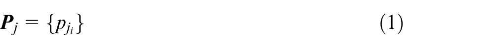
Industrial automated production technologies have been the research focus of many recent studies, comprising the two research streams of automated assembly and automated product testing. Camera lens-shake detection is an effective way to measure the quality of video cameras during zooming. Conventional testing methods involve time-consuming manual operation procedures. This study proposes a novel automated camera lens-shake detection method, in which real-time visual tracking of two arbitrary features is used to measure and analyze camera zooming quality. The camera lens-shake detection approach can be used to screen out video cameras for the purpose of quality control. It can be effectively employed to replace conventional testing methods and enhance efficiency and stability of product manufacturing.
Keywords
Introduction
Among various automated production and manufacturing technologies, industrial cameras have been widely used in measurement and assembly tasks. Castellani et al. 1 proposed a new non-contact and non-destructive method for automatic inspection of microstructures by employing a microscopic camera to monitor the vibration of the structure. Ogun et al. 2 presented a two-stage inspection process in which a machine vision system is used to detect potentially defective regions on parts over a much wider field of view than is currently covered by commercial products. Wen et al. 3 developed a computer-vision-based object recognition system to deal with online inspection for hose assembly. Features of hoses and related fasteners were analyzed to perform image processing, object extraction, and feature recognition. Wang et al. 4 developed an alternative measurement sensor for onsite inspection of hull plates, providing accurate quantitative results with high efficiency. Chen and Chang 5 incorporated a linear regression diagnostic model with digital image processing techniques to inspect TFT-LCD Mura defects automatically. Product manufacturing with an increasingly refined process has required higher image resolution and greater functional stability in industrial vision and measurement sensors.
In recent years, many researchers have studied the phenomenon of camera shake. Fergus et al. 6 determined the image blurring degree through the distribution of local image convolution. Hirsch et al. 7 developed a forward model based on an efficient filter flow framework, which can remove blurred images caused by camera shake efficiently. Tong et al. 8 presented a new blur detection scheme based on edge type and sharpness analysis using the Haar wavelet transform. This scheme can determine whether an image is blurred or not and to what extent an image is blurred caused by camera shake. Ogino et al. 9 used a camera to observe the designed test pattern and estimate the degree of camera shake for roll, pitch, and yaw motion of the camera. Oh et al. 10 used changes in image frequency spectrum and the contour orientation of the image spectrum to measure camera shake. Jodoin et al. 11 separated moving objects by background segmentation, and used the motion vector of the object to evaluate camera shake. Nishi and colleagues 12,13 processed the images captured by a camera with different postures. Hu et al. 14 and Yue et al. 15 both improved image blur caused by camera shake based on depth information of an image. Baxansky and Tzur 16 designed a new algorithm to analyze the degree of contour blurring of a single image and other related techniques to measure and correct camera shake caused by camera motion during regular camera shooting. All of these research results focused on the detection of camera shake caused by external motion. However, there has been no related research aimed at measuring the camera lens-shake caused by the interior camera lens during zooming. Currently, all cameras with this defect must be filtered and eliminated at a time-consuming quality control stage with human eye inspection.
Camera lens-shake detection is primarily focused on the measurement of manufacturing tolerances exceeding the unacceptable range of zoom lenses in terms of the image shift during the zooming process. Thus, the zooming performance of each manufactured video camera can be ensured at the quality control stage. In fact, current production lines mainly adopt manual inspection. The level of camera lens-shake near the principal point is estimated by a human operator only while the lens is zooming in or out. This detection method not only consumes a lot of time but also gives poor accuracy.
The method proposed in this article can estimate the position of the principal point of an image during the zooming process by means of tracking two arbitrary feature points. Most importantly, through the shake level of the two feature points, the camera lens-shake around the principal point can be effectively calculated during the zooming process.
Problem formulation
The camera zoom function mainly involves zooming in or out images by changing the focal length between the zoom lens and the image surface using rotating internal gears inside the camera. For a camera with ideal lens assembly, the image in the camera will be zoomed in and out stably and smoothly. However, when the zooming is performed by a lens with poor manufacturing and assembly, camera lens shaking occurs during the zooming process. The phenomenon leading to shaking images is called camera lens-shake. The geometry of the camera lens-shake occurring when zooming an image is shown in Figure 1, in which one can see the varying camera frame
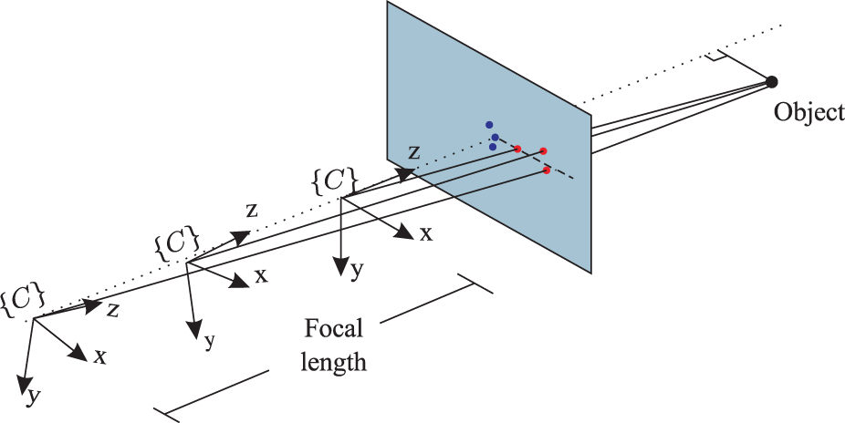
Camera lens-shake.
Existing camera lens-shake inspection approach
The traditional camera lens-shake inspection process is as follows.
Estimate the position of the principal point on the image with a typical offline calibration procedure for cameras.17–19
Overlap and align the positions of the selected feature point and the principal point on the image.
Start the zoom function, estimate the shaking level on the image, and define the maximum value of this shaking level as the camera lens-shake s on this particular camera manually, as shown in Figure 2.
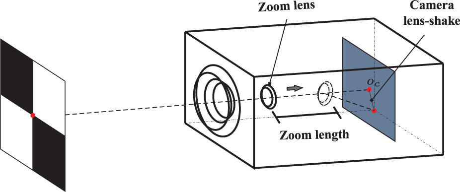
Camera lens-shake detection.
Proposed camera lens-shake measurement approach
Compared with the traditional camera lens-shake detection technique, one does not need to perform any of the steps mentioned earlier, such as calculating the position of the principal point offline, aligning the selected feature point with the position of the principal point, or processing the measurement of camera lens-shake manually. The proposed approach can largely reduce the detection time, and avoid accumulated errors due to miscalibration. The steps of the proposed automated camera lens-shake detection process are as follows.
Place the video camera to be tested in front of a
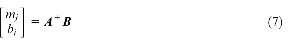
Start the zooming function of the video camera and pause at each predetermined zooming level. Extract the image coordinates of the two corner points, a and b, and then add their coordinates to the corresponding point group matrix,
where
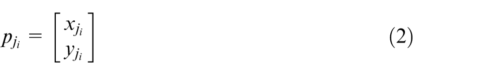
and i represents the zooming level of a camera,
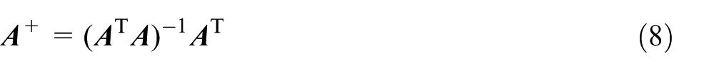
Using the method of least squares, one can fit the equations of the line with the data points in the two point groups
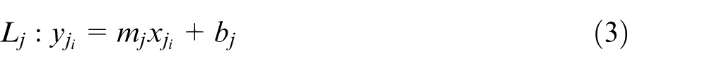
one can determine
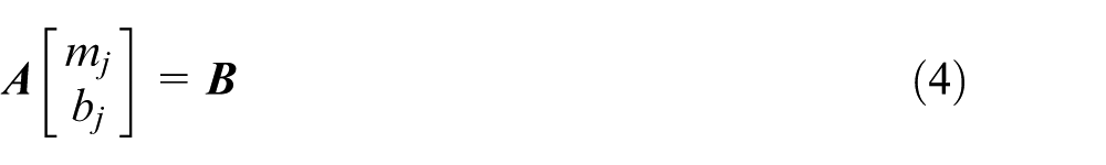
where
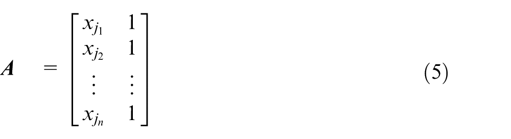
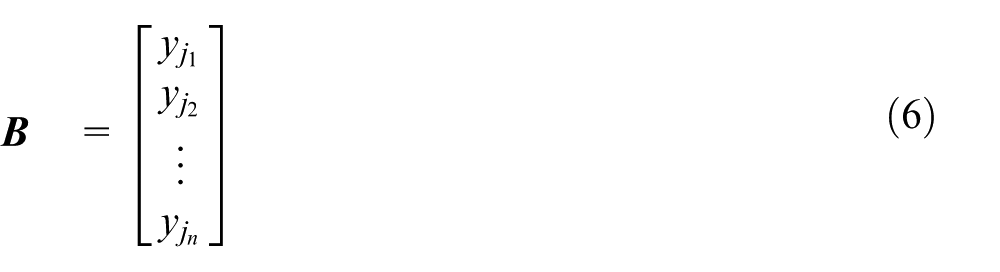
In particular, the least squares estimate of
where
With the intersecting point of
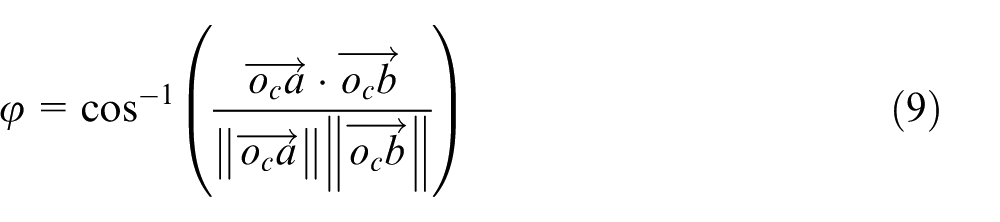
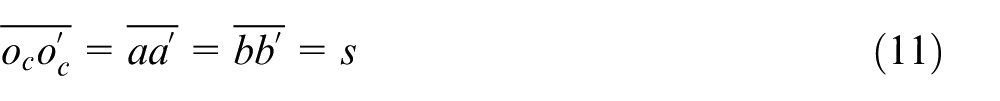
Based on the relative geometric relation of the three points
where
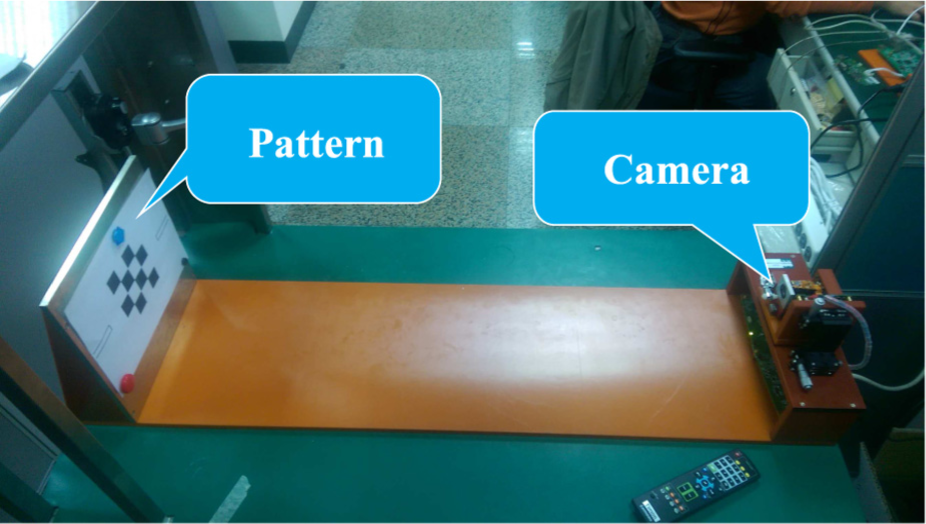
System configuration.
Calculation of camera lens-shake level
The fact that camera lens-shake s is caused by a shaking lens in the zooming process leads to shaken images. Therefore, the magnitude and direction of the captured feature points and camera lens-shake are considered the same. It can be expressed using the following formula; the shaking level of a feature point on the image is illustrated in Figure 4
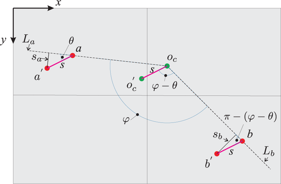
Camera lens-shake estimation via the trajectories of two feature points.
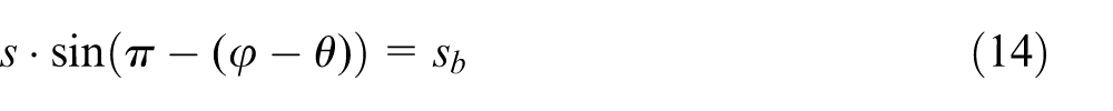
At this moment, the included angle between the line
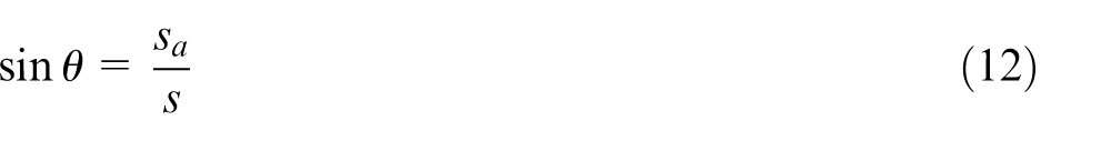
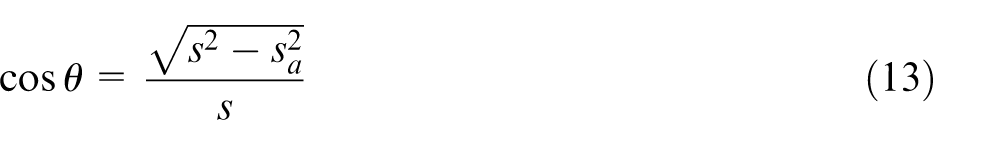
Similarly, the normal shake
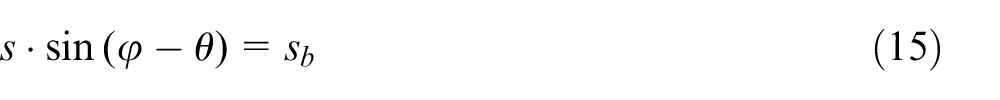
One can thus see that
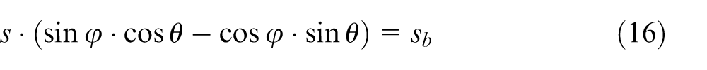
After substituting equations (12) and (13) into equation (16), it can be sorted out as
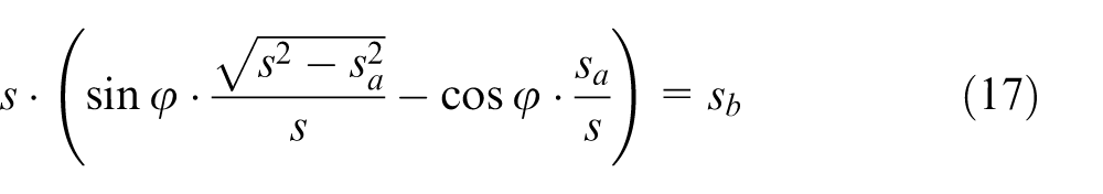
It follows from equation (17) that
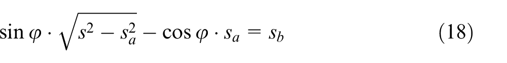
Re-arrange equation (18) and one can see that
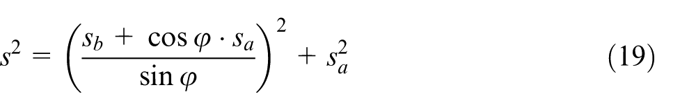
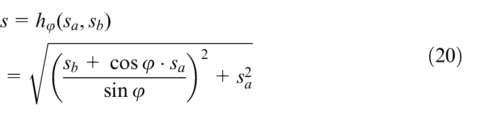
Based on all available data, including
Singularity avoidance
When
Experimental results
In the experimental system, two cameras VC-B20D manufactured by Lumens Digital Optics Incorporation were tested for quality inspection. The two cameras are labeled
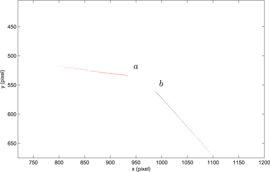
Image tracking results of a passed camera.
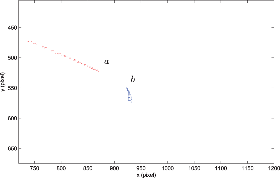
Image tracking results of a failed camera.
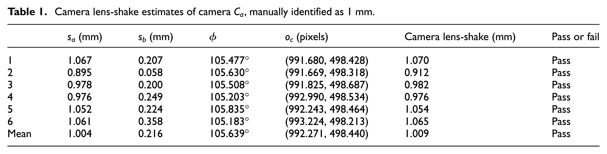
For camera
Camera lens-shake estimates of camera
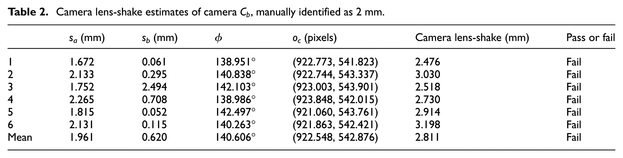
Camera lens-shake estimates of camera
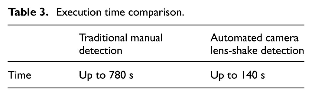
Execution time comparison.
Conclusions
A novel approach to measuring the camera lens-shake caused by unacceptable manufacturing tolerance of the zoom lenses is proposed in this research. The detection method can be implemented to replace the existing human inspection approach by real-time visual tracking of two arbitrary features. Such two features can be selected as the corner points on a chessboard-type pattern board to ensure robust and precise measurements. To avoid computation singularity effectively, the image trajectories of the two corner points must not be collinear. This can be resolved by either preselecting two cornet points in a trial zoom or selecting the two most suitable trajectories online from three trajectories measured. The proposed approach has been validated by experimenting with industrial cameras to demonstrate its effectiveness and efficiency. According to the experimental results, this detection approach appears to be stable, accurate, and easy to carry out.
Footnotes
Acknowledgements
The author would like to thank Chi-Cheng Wang for assisting with the implementation of the experimental system.
Funding
The author disclosed receipt of the following financial support for the research, authorship, and/or publication of this article: This work was supported by Lumens Digital Optics Incorporation (grant number 203A203) and the Ministry of Science and Technology, Taiwan, R.O.C. (grant number NSC 101-2221-E-027-058-MY3).