
Abstract
A lot of research has been undertaken in the area of conventional machining to study the effect of process parameters, tool geometry, machining environment and so on on machinability. But only recently, the research community has started analysing the carbon footprint of manufacturing processes. But very few articles could be located that attempted simultaneous minimisation of specific cutting energy and back force over a wide domain of process and tool-geometric parameters. This article has experimentally studied the effect of variation in depth of cut, feed, nose radius and tool geometry on simultaneous minimisation of specific cutting energy and back force while turning AISI 1060 steel with uncoated carbide inserts under dry machining environment. Minimisation of specific cutting energy and back force as individual criterion leads to conflicting choice of machining parameters. A combined criterion based on specific cutting energy and back force has been defined and for the minimisation of the same, cutting tools with positive rake need to be used, with high feed and moderate depth of cut.
Keywords
Introduction
A lot of research has been undertaken, till 2000 and beyond, in the area of conventional machining in studying the effect of process parameters, tool geometry, machining environment, different types of furtherance in the form of assists (ultrasonic-assist, vibration-assist) and so on on various machinability indices with an aim to improve the same. But only recently, the research community has started analysing the carbon footprint of manufacturing processes.
Klocke and Eisenblatter 1 indicated the importance of evaluating the environmental impact of different machining processes. They indicated the use of cryogenic cooling, minimum quantity lubrication (MQL), coated carbides, ceramics, cubic boron nitride (cBN) and diamonds as possible alternative dry machining technologies. Gupta and Laubscher 2 in a review article discussed sustainable machining of titanium alloys. Some of the techniques identified were optimal choice of process parameters, tool geometry and tool material, MQL, cryogenic cooling with use lubricants and so on. Pervaiz et al. 3 attempted one such technique, MQL with vegetable oil, in enhancing machinability of titanium alloy. Tazehkandi et al. 4 also applied bio-degradable vegetable oil using MQL technique to attempt to develop sustainable machining of nickel-based alloys. Kuram et al. 5 studied the effect of vegetable-based cutting oil in end-milling of AISI 304 steel and selected suitable cutting parameters for optimal energy, tool life and surface roughness.
Hollies 6 reported enhanced tool life in turning of titanium alloys with liquid CO2 much earlier. Uehara and Kumagai,7,8 along with Fillippi and Ippolito, 9 employed liquid nitrogen cooling and found a lesser force requirement and improved tool life in face milling. Much later in 1993, Paul et al. 10 reported a detailed experimental study of cryogenic cooling on grindability of different steels. Similarly, Venugopal et al. 11 and Nandy et al. 12 studied the effect of cryogenic cooling and high-pressure cooling, respectively, on the improvement of machinability of Ti alloy. Strano et al. 13 compared the benefits of cryogenic cooling over conventional coolant while turning titanium alloy.
It is to be noted that the motivation of these studies has been the improvement in machinability but never energy efficiency. Dhar et al. 14 did mention the pollution aspects of conventional cooling and environment friendliness of cryogenic cooling. This article also highlighted the aspect of dimensional accuracy besides other machinability indices.
Kordonowy 15 estimated the machining energy to be around 52% of the total energy consumption in a milling machine. Gutowski et al. 16 found environmentally sustainable manufacturing to be emerging as a significant competitive index for the manufacturer. Although they indicated that energy for chip formation was around 15% of the total energy required in machining, Balogun and Mativenga 17 indicated that the cutting energy was typically lower than the energy required by a machine tool operating at no load. However, Zackrisson 18 indicated that the largest environmental impact was associated with the use and disposal of products rather than the manufacturing.
Gutowski et al. 19 proposed that total energy requirement in machining was the sum of idle energy and energy required for material removal. He et al. 20 identified different sources of energy consumption in a machine tool like a spindle (both idle and cutting period), axes’ motors for rapid and cutting feed motion, automatic tool changer, coolant pumps and other accessories like fans and controllers.
Mativenga and Rajemi 21 attempted an optimal selection of cutting parameters while turning of medium carbon steel under different combinations of cutting speed, feed and depth of cut. They minimised the total energy of machining a component, and explored the synergy between minimal cost and energy.
Aramcharoen and Mativenga 22 introduced the influence of tool wear on energy requirement in machining processes. In milling of stainless steel with uncoated carbide tools, they observed synergy between cycle time and energy requirement. Yan and Li 23 attempted an optimisation of material removal rate, energy and surface roughness using grey relational analysis while milling medium carbon steel with varying feed, cutting speed, axial and radial depth of cut.
Pusavec et al. 24 undertook an experimental study of sustainable turning of Inconel 718 using uncoated carbide inserts at different combinations of cutting velocity, feed and depth of cut under dry, MQL, cryogenic and cryo-MQL mode. Pusavec et al. 25 attempted minimisation of cutting forces and power consumption along with increasing tool life and productivity as sustainability indices using a combination of the statistical design of experiments and genetic algorithm.
Survey of previous work indicates that enough work has been undertaken even in the direction of simultaneous optimisation of machining energy, surface roughness and tool life using combinations of statistical design of experiments and soft computing. Survey also indicated the importance of energy in machining. But barring a few studies, no emphasis has been provided to dimensional accuracy. Most importantly, no study could be located that simultaneously studied the effect of variation in cutting velocity, feed, depth of cut and tool geometry (rake angle, inclination angle, principal cutting edge angle and nose radius) on machining energy and dimensional accuracy.
Thus, this article aims to study experimentally the effect of variation in depth of cut, feed, nose radius and tool geometry on simultaneous minimisation of specific cutting energy and back force (that governs the dimensional tolerance in turning) while turning AISI 1060 steel with uncoated carbide inserts under dry machining environment. The simultaneous minimisation of specific cutting energy and back force has been attempted by converting them into the non-dimensional form.
Experimental
Experimental set-up
Straight turning of AISI 1060 medium carbon steel bar of 180 mm diameter and 750 mm length was undertaken in an 11-kW centre lathe (HMT, India) fitted with variable frequency drive (ABB, India) so that the chosen cutting velocity (90 m/min) can be achieved despite some minor variations in the diameter of the workpiece. The experimental set-up is shown in Figure 1. Turning was carried out with steel cutting grade uncoated tungsten carbide cutting tool insert (Widia; P-20 grade) under dry machining environment for 20 s. During the experiments, three different types of cutting tool inserts were employed so as to vary the nose radius, rake angle and inclination angle. Table 1 lists all the experimental conditions. The process parameters were chosen to replicate industrial semi-finish turning for the combination of the employed grade of the cutting tool and work material.14,26
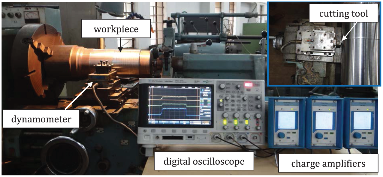
Photographic view of the experimental set-up (inset: cutting tool mounted on cutting force dynamometer).
Experimental conditions.
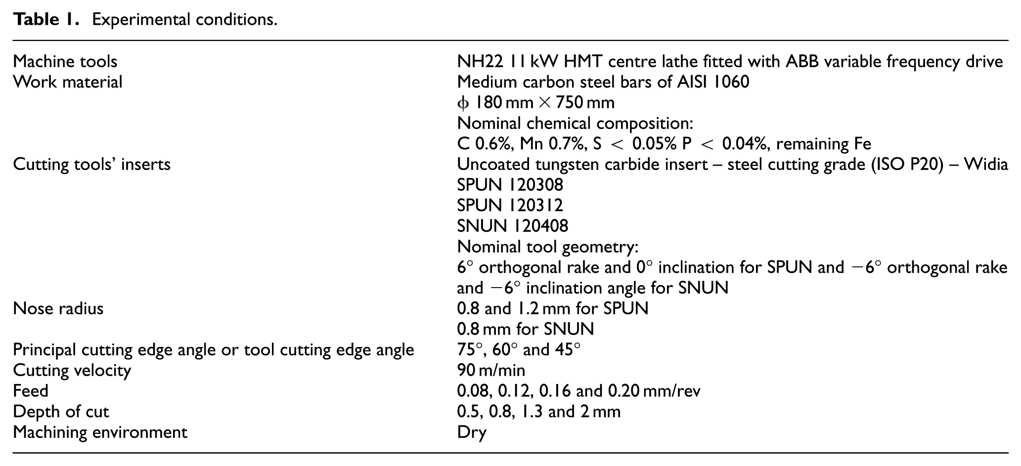
The cutting tool holder along with dynamometer was swivelled about a vertical axis (or cutting velocity vector) by 15° and 30° so that using the same set of inserts the principal cutting edge angle can be varied. Such swivelling provided 60° and 45° principal or tool cutting edge angle, whereas the principal or tool cutting edge angle was 75° when the tool holder was not swivelled.
Experimental measurements
During straight turning, the feed and depth of cut were varied at four different levels for each of the principal or tool cutting edge angles and cutting tool inserts. The three orthogonal components of the cutting forces, namely, feed force (Ff), back force (Fp) and cutting force (direction coinciding with cutting velocity vector) (Fc), were monitored during turning using three-component piezo-electric turning dynamometer (Model 9257B; Kistler), three single-channel universal charge amplifier (Model 5015A1000; Kistler) and a digital storage oscilloscope (Model 54624A; Agilent).
Each experimental trial was repeated thrice. The reported forces are average of those three measurements. The range was also calculated to ascertain uncertainty of measurement. The specific cutting energy (pc) was calculated using the following formula neglecting the contribution of feed force as the feed rate, or feed velocity is almost two to three orders less than the cutting velocity
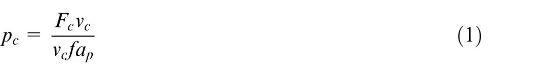
where vc is the cutting velocity, f is the feed and ap is the depth of cut in appropriate units so that specific cutting energy is determined (J/mm3).
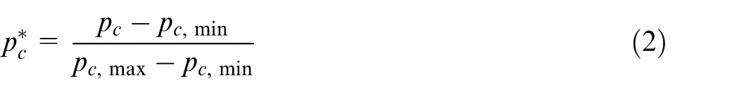
The specific cutting energy and back force were non-dimensionalised between 0 and 1 over the entire domain of this experiment, respectively, using the following formulae
and
where pc* and Fp* are the non-dimensional forms of specific cutting energy and back force, respectively; p c,min and F p,min are the minimum of specific energy and back force, respectively, and p c,max and F p,max are their maximum values. The minimum and maximum values of these indices were obtained for the entire experimental domain.
Results and discussions
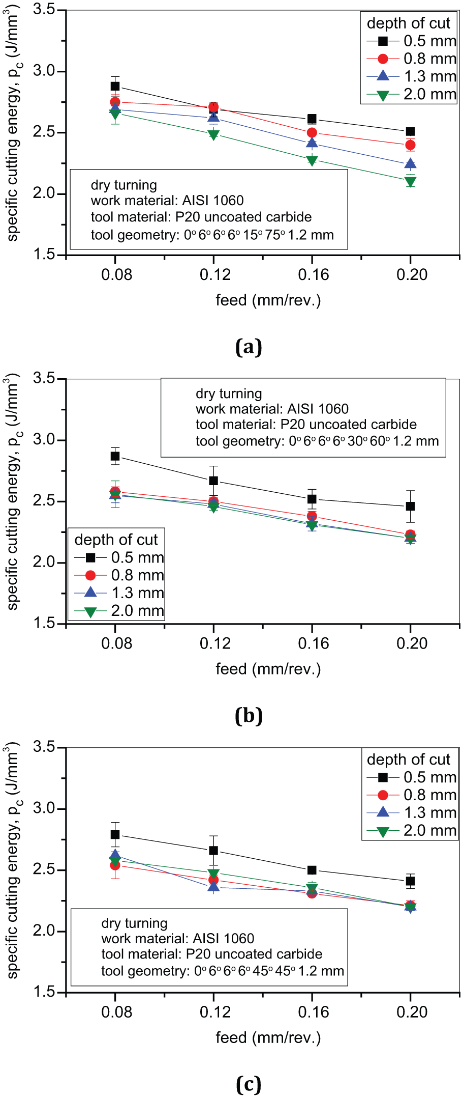
Figures 2–4 depict the variation in specific cutting energy while straight turning AISI 1060 steel bars with uncoated carbide, for different feed, depth of cut, principal or tool cutting edge angle and rake angle. Figure 2 reveals the experimental observations for a positive rake tool with a nose radius of 0.8 mm, whereas similar results are depicted in Figure 3, for the same insert but with a nose radius of 1.2 mm. The increase in feed, irrespective of the variation in depth of cut, principal or tool cutting edge angle and nose radius, has provided a reduction in specific cutting energy. Specific cutting energy is related to uncut chip thickness (true-feed).
26
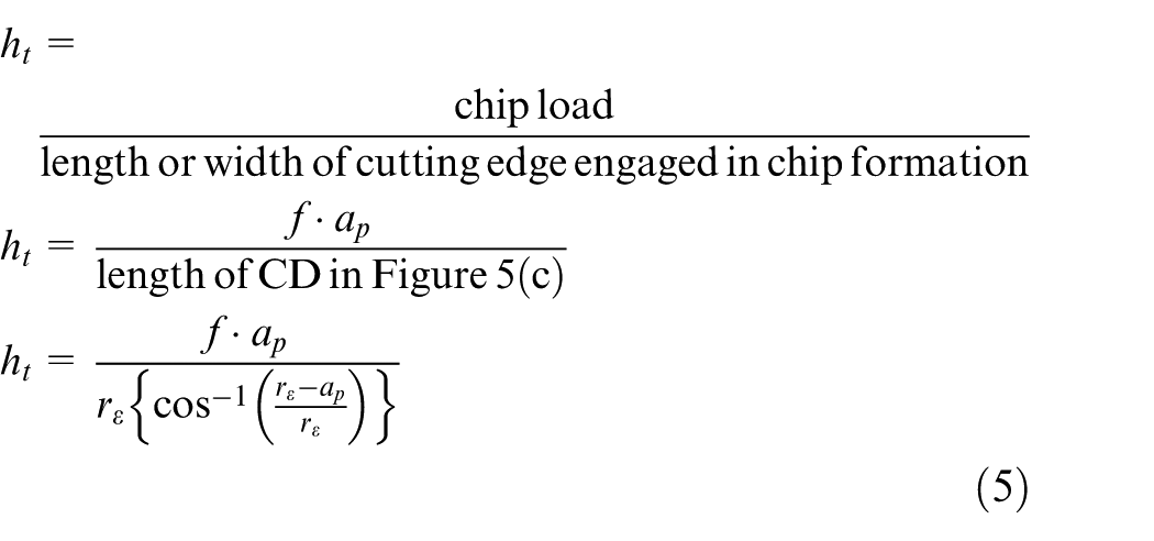
The average true-feed or uncut chip thickness can be calculated as the ratio of chip load to length or width of cutting edge engaged in chip formation. Figure 5(a) and (b) shows the engagement of a single point turning tool with the work material when
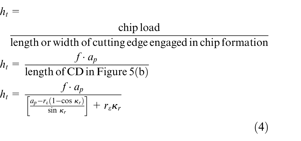
and for the second condition, the same can be expressed as
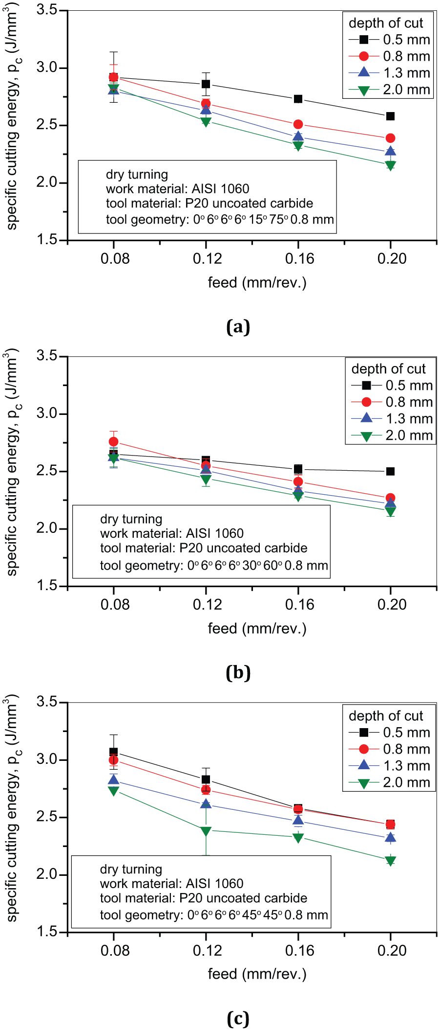
Variation in specific cutting energy with feed while dry turning AISI 1060 steel with uncoated carbide (P20 grade) insert (SPUN) with a nose radius of 0.8 mm at different depths of cut and principal cutting angles of (a) 75°, (b) 60° and (c) 45°.
Variation in specific cutting energy with feed while dry turning AISI 1060 steel with uncoated carbide (P20 grade) insert (SPUN) with a nose radius of 1.2 mm at different depths of cut and principal cutting angles of (a) 75°, (b) 60° and (c) 45°.
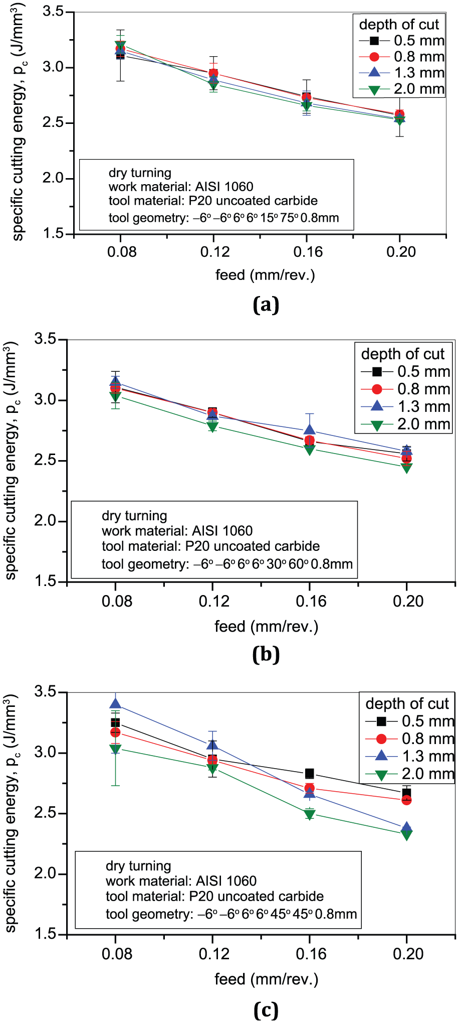
Variation in specific cutting energy with feed while dry turning AISI 1060 steel with uncoated carbide (P20 grade) insert (SNUN) with a nose radius of 0.8 mm at different depths of cut and principal cutting angles of (a) 75°, (b) 60° and (c) 45°.
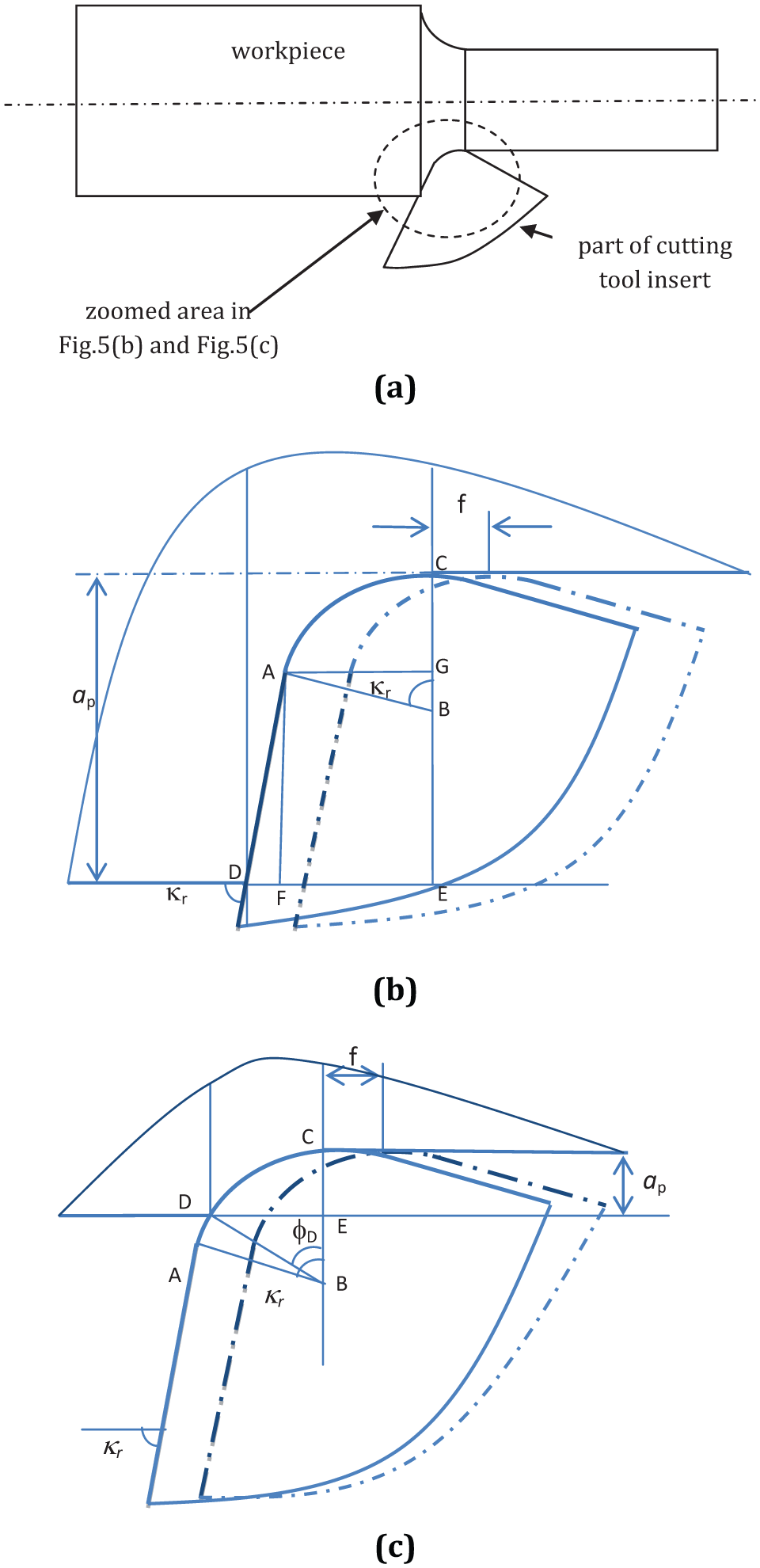
(a) Engagement of a single-point turning tool with the work material during straight turning – general depiction, (b) engagement of a single point turning tool with the work material when
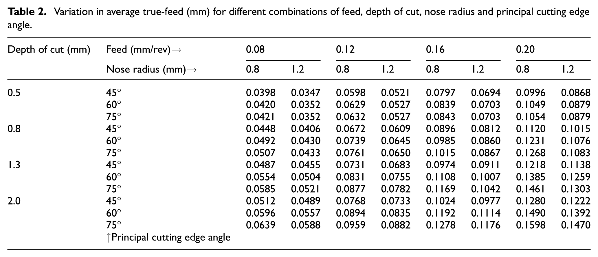
Table 2 shows the variation in average true-feed, which has been calculated using equations (4) and (5), within this experimental domain for different combinations of feed, depth of cut, nose radius and principal cutting edge angle. As the feed increases, the average true-feed also increases irrespective of the depth of cut, nose radius and principle cutting edge angle as can be noted in Table 2. Reduction in average true-feed makes the effective rake angle less positive due to the role of edge radius, 26 which is typically in the range of 10–50 μm on most of the uncoated carbide cutting tool inserts. This is attributed to explain the reduction in specific cutting energy with an increase in feed.
Variation in average true-feed (mm) for different combinations of feed, depth of cut, nose radius and principal cutting edge angle.
In orthogonal machining, specific cutting energy can be expressed as 27
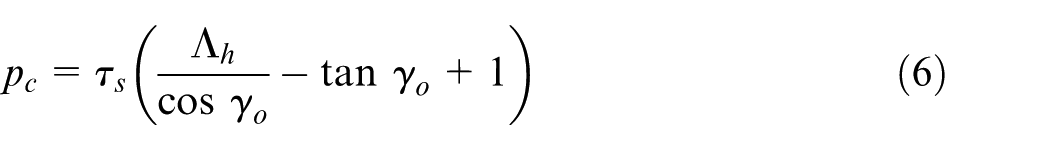
where pc is the specific cutting energy, τs is the yield shear strength of the work material, Λ h is the chip reduction coefficient or chip compression ratio and γo is the orthogonal rake angle.
Although these experimental conditions do not conform to orthogonal machining, still the basic trend of variation in specific energy can be explained by the basic theory of machining. Table 2 shows that an increase in depth of cut increases the average true-feed, which in turn leads to more effective positive rake angle. Kronenberg 28 proposed the following relationship between chip reduction coefficient and rake angle

where
Thus, as the average true-feed increases making the effective rake angle more positive, the chip reduction coefficient
Comparing Figures 2 and 3, the effect of nose radius on specific cutting energy can be realised. The increase in nose radius provides very slight reduction in the average true-feed when the depth of cut is less as noted in Table 2. Thus, it is expected that larger nose radius would provide higher specific cutting energy. This has not been consistently observed from the experimental data.
Once again, the effects of feed, depth of cut and principal cutting edge angle on specific cutting energy, as can be seen in Figure 4, follow the sample trends as noted in Figures 2 and 3. In Figure 4, the cutting tool insert had a negative rake angle and a negative inclination angle. These provide higher chip reduction coefficient as per equation (7) and hence yielded higher specific energy requirement as compared to cutting tool inserts with positive rake angle.
Thus, the minimisation of specific cutting energy would occur when feed and depth of cut are simultaneously high. The effects of nose radius and principal cutting edge angle are negligible. However, employing negative rake tool increases specific energy requirement.
In turning, the cutting force has three orthogonal components, and they are feed force

where Fp is the back force, τs is the yield shear strength of the work material, ap is the depth of cut, f is the feed, Λ h is the chip reduction coefficient or chip compression ratio, γo is the orthogonal rake angle and κr is the principal or tool cutting edge angle.
Figures 6–8 depict the effect of feed, depth of cut, principal cutting edge angle, nose radius and rake angle on the back force. Irrespective of the rake angle, nose radius and principal cutting edge angle, the back force increases with an increase in feed and depth of cut as shown in Figures 6–8, which may be attributed to equation (8). But the effects of feed and depth of cut are not linearly proportional. This needs to be pointed out that the variation in feed and depth of cut affects the average true-feed which, in turn, affects chip reduction coefficient. The increase in feed leads to an increase in machining temperature which brings down the yield shear strength of the work material. All these phenomena yield non-linear effects of feed and depth on the back force.
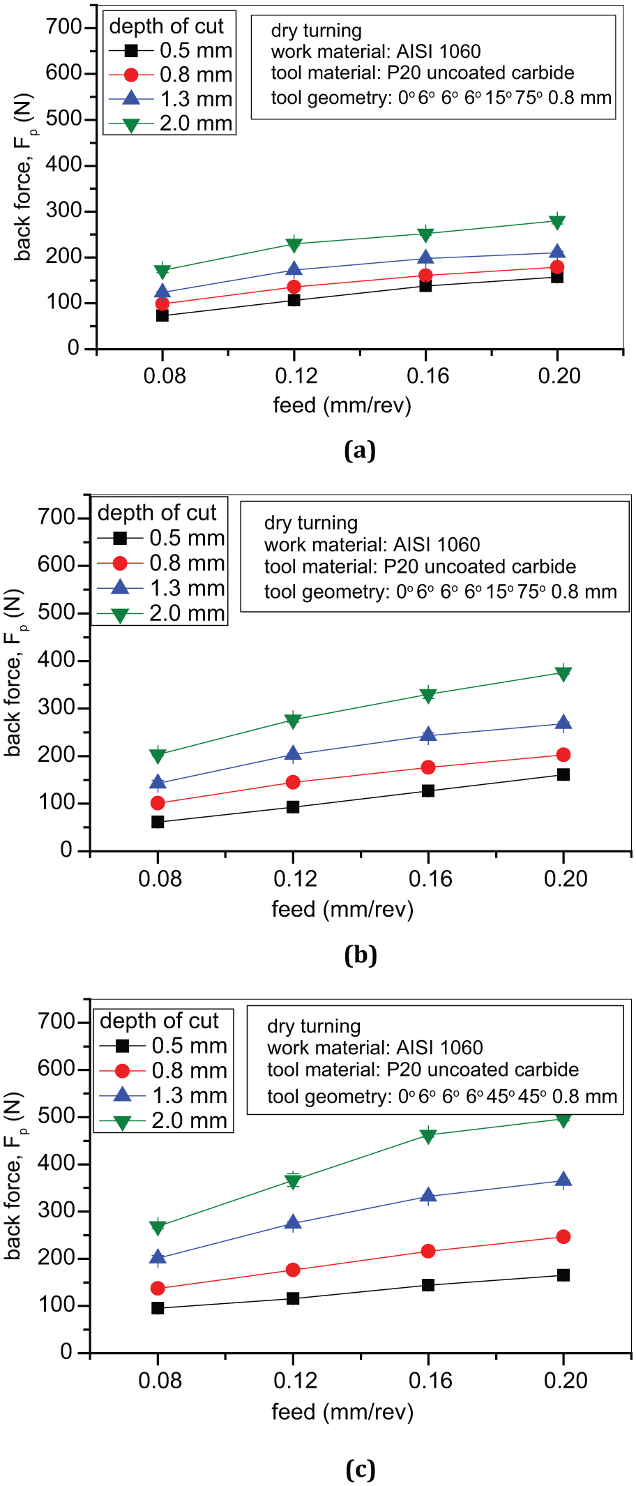
Variation in back force with feed while dry turning AISI 1060 steel with uncoated carbide (P20 grade) insert (SPUN) with a nose radius of 0.8 mm at different depths of cut and principal cutting angles of (a) 75°, (b) 60° and (c) 45°.
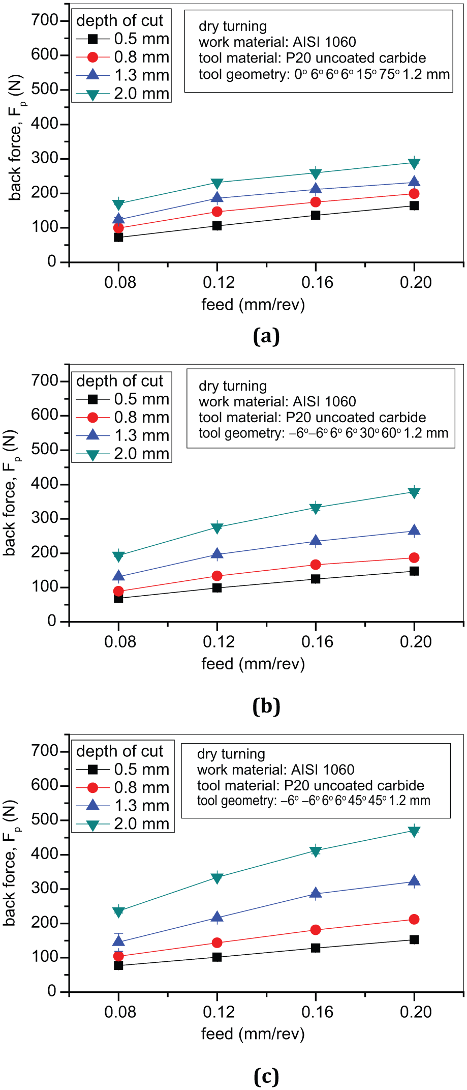
Variation in back force with feed while dry turning AISI 1060 steel with uncoated carbide (P20 grade) insert (SPUN) with a nose radius of 1.2 mm at different depths of cut and principal cutting angles of (a) 75°, (b) 60° and (c) 45°.
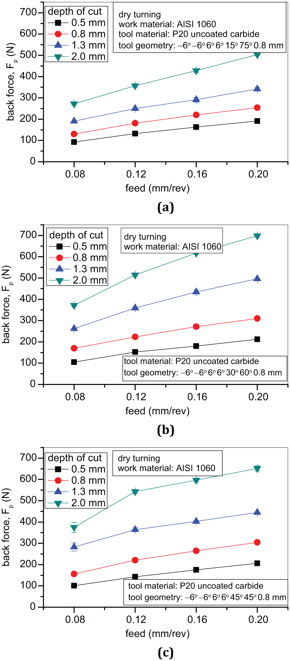
Variation in back force with feed while dry turning AISI 1060 steel with uncoated carbide (P20 grade) insert (SNUN) with a nose radius of 0.8 mm at different depths of cut and principal cutting angles of (a) 75°, (b) 60° and (c) 45°.
All the three figures (Figures 6–8) also indicate an increase in the back force with a reduction in principal or tool cutting edge angle. This can be attributed to more apportionment of thrust force (FD) in the radial (back) direction due to a change in the orientation of the principal cutting edge. The increase in nose radius has not affected the back force significantly as can be revealed by comparing Figures 6 and 7. But the use of cutting tool with negative rake angle as in Figure 8 compared to cutting tool with positive rake angle (Figures 6 and 7) has provided the significantly higher back force. This may be attributed to the higher value of
Hence, minimum back force can be obtained with low feed, low depth of cut and high principal or tool cutting edge angle employing cutting tools with positive rake. Thus, minimisation of specific cutting energy and back force as individual criterion leads to conflicting choice of machining parameters.
Specific cutting energy and back force have been non-dimensionalised as per equations (2) and (3). Figures 9–11 show the variation in sum
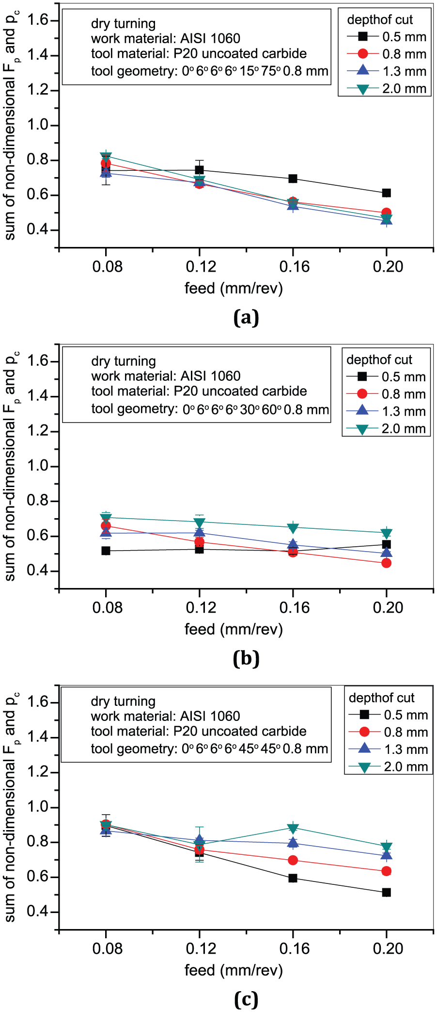
Variation in sum of non-dimensional specific cutting energy and back force with feed while dry turning AISI 1060 steel with uncoated carbide (P20 grade) insert (SPUN) with a nose radius of 0.8 mm at different depths of cut and principal cutting angles of (a) 75°, (b) 60° and (c) 45°.
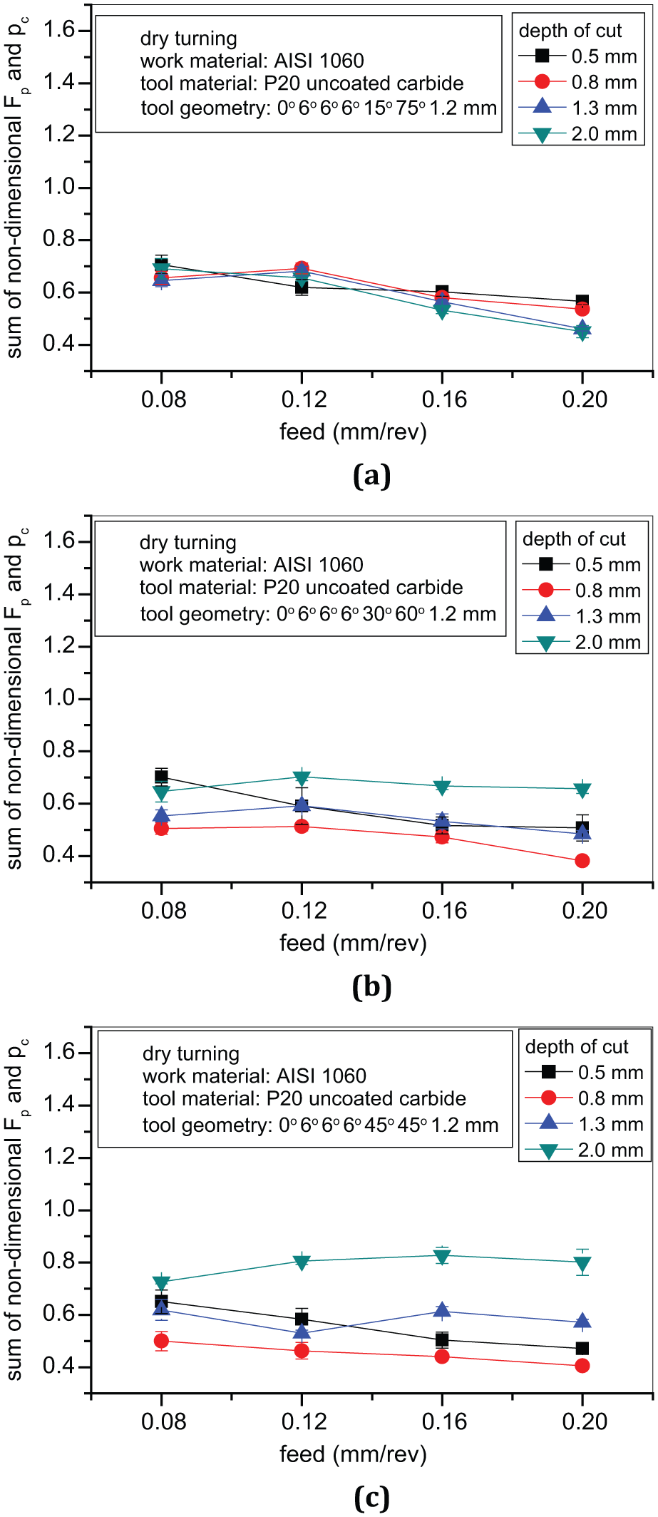
Variation in sum of non-dimensional specific cutting energy and back force with feed while dry turning AISI 1060 steel with uncoated carbide (P20 grade) insert (SPUN) with a nose radius of 1.2 mm at different depths of cut and principal cutting angles of (a) 75°, (b) 60° and (c) 45°.
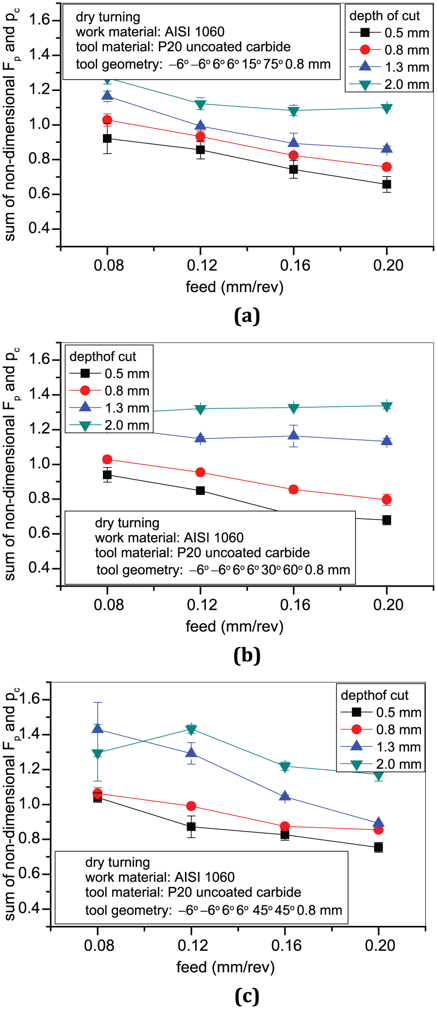
Variation in sum of non-dimensional specific cutting energy and back force with feed while dry turning AISI 1060 steel with uncoated carbide (P20 grade) insert (SNUN) with a nose radius of 0.8 mm at different depths of cut and principal cutting angles of (a) 75°, (b) 60° and (c) 45°.
Conclusion
In this work, minimisation of a combined criterion of specific cutting energy and back force (that governs dimensional tolerance) has been attempted for turning of medium carbon steel with uncoated carbide insert over a wide domain of feed, depth of cut, nose radius, principal cutting edge angle and rake angle. The following conclusions can be drawn from the analysis of the experimental results:
In turning of medium carbon steel, minimisation of specific cutting energy takes place when feed and depth of cut are simultaneously high. The effects of nose radius and principal cutting edge angle are negligible on specific cutting energy. However, employing negative rake tool increases specific energy requirement.
However, minimum back force can be obtained with low feed, low depth of cut and high principal cutting edge angle employing cutting tools with positive rake. Thus, minimisation of specific cutting energy and back force as individual criterion leads to conflicting choice of machining parameters.
A combined criterion based on specific cutting energy and back force has been defined and for minimisation of the same, cutting tools with positive rake need to be used, at high feed and moderate depth of cut.
Footnotes
Declaration of conflicting interests
The author(s) declared no potential conflicts of interest with respect to the research, authorship and/or publication of this article.
Funding
The author(s) received no financial support for the research, authorship and/or publication of this article.