
Abstract
Robotic boring is an effective way to implement finish machining of intersection holes. However, to a certain extent, its application is limited due to the low rigidity of the robot, whose stiffness brings on high vibration levels. In this study, a new approach based on an equivalent stiffness is proposed to gain a fundamental understanding for the cutting mechanism and vibration performance of a robotic boring system. In the approach, the robotic boring system in one direction is regarded as a mass–spring–damping unit according to the structure characteristics of the robot. Thus, the whole robotic boring system is equivalent to a mass–spring–damping group in three-dimensional space. The stiffness and natural frequency of the robot system were measured by stiffness identification and a modal test on an ABB IRB 6600-175/2.55 robot. An equivalent three-dimensional finite element model based on this approach was established to simulate the robotic boring process, and a verification experiment was conducted to determine the accuracy of the finite element simulation. The results show that the simulated cutting force components and the amplitude in the feed direction are in good agreement with the experiment under different cutting conditions, and this proposed approach is feasible.
Keywords
Introduction
The connecting holes distributed in crucial locations of large aircraft parts are called intersection holes and are such as undercarriage and fuselage connecting holes, aircraft wing connecting holes, vertical stabilizer and fuselage connecting holes. In order to eliminate part manufacturing errors and the posture deviations resulting from parts assembly, finish machining of intersection holes is essential for ensuring assembly coordination. Currently, intersection holes are usually machined in specialized drilling equipment which is fixed on a customized finish machining platform. However, this method results in inevitable disadvantages such as high cost, poor efficiency and large assembly stress. As robots are widely used in aircraft manufacturing, robotic boring becomes an ideal choice to replace the current machining method. By this means, these disadvantages can be efficiently overcome, and an automated level of machining can be significantly enhanced.
A robotic boring system mainly comprises a robot and an end-effector. The end-effector which is attached to the end of the robot achieves the rotational and feed movement. The robot is flexible with a high degree of freedom (DOF) and used to provide the exact position and posture for the end-effector. Nevertheless, the serial structure of an articulated robot has a much lower stiffness than that of a standard machine tool. Hence, vibration is more likely to happen than in the machine tool system when the cutting force is applied in the robotic boring system. Detrimental results may also arise, such as poor surface quality, unpleasant noise and accelerated wear of the cutting tool. 1 In practice, it has also been found that a robot system is more inclined to vibrate than machine tool system under the same conditions. This has become a major limitation in the application of robot cells. 2
Vibration in robotic boring is basically an interaction among the robot system, the material and the tool, with the result that it is hard to obtain the cutting mechanism and vibration performance of a robotic boring system using an analytical and experimental approach. Aiming at this situation, many authors have illustrated that sophisticated finite element (FE) simulations of the metal cutting process can be carried out using advanced general-purpose commercial FE codes. 3 However, most machining systems in FE simulation were regarded as a rigid body with sufficient stiffness.4–7 Only a few consider the effect of machining system in terms of chatter and stability analysis. Hajmohammadi et al. 8 investigated thermal effects resulting from friction and plastic deformations on the stability of a 1-DOF system through thermo mechanical FE analysis of an orthogonal machining process. Mahnama et al. 9 simplified the machine tool system as a 1-DOF system and predicted the effects of various conditions on the onset of chatter using FE simulation. Later, they simulated the stability of a 1-DOF machining system by the FE simulation method of orthogonal machining and obtained the interrelationship between the chatter vibration and the chip formation process. 10 However, from the structure characteristics of the robot, it is easy to see that the robot system should not be simply regarded as a rigid body or a 1-DOF system in the FE simulation. Hence, the above simulations are not appropriate for the simulation of robotic boring, and an alternative approach should be sought.
In this article, the equivalent stiffness principle of the robot is first presented. Second, to obtain the stiffness and natural frequency of the robot system, the stiffness identification and modal test are performed on an ABB IRB 6600-175/2.55 robot. Then, an equivalent three-dimensional (3D) FE model is established to simulate the boring process. Simulated and experimental results are compared and analyzed in section “Experimental verification and discussion.”
Equivalent principle of the robot
The consideration of robot stiffness is critical for robotic boring due to the inherent low rigidity of the robot. According to the structure characteristics of the robot, 11,12 the robotic boring system in one direction can be regarded as a mass–spring–damping unit. Thus, the whole robotic boring system is equivalent to a mass–spring–damping group in 3D space and can be simplified as shown in Figure 1.
The equivalent schematic diagram of the robotic boring system.
For the equivalent system, the structural vibrations of both the workpiece and boring insert in the Cartesian coordinate frame (X, Y, Z) can be expressed as follows
Equation (1) can be further written as follows
where
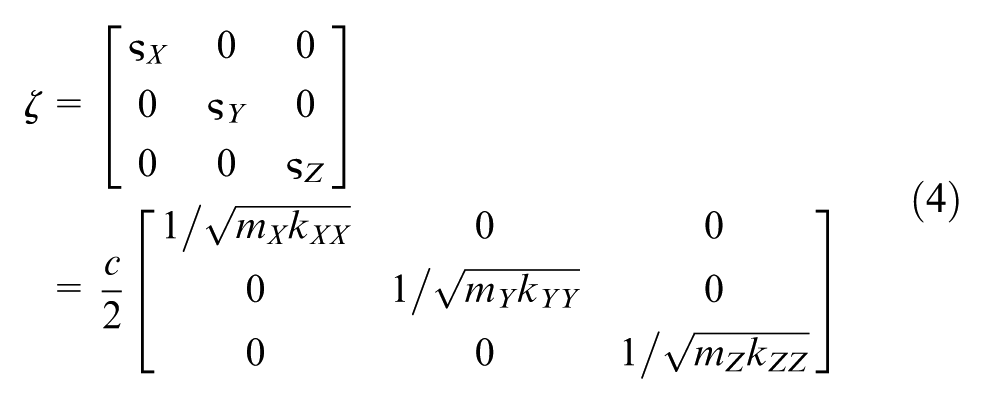
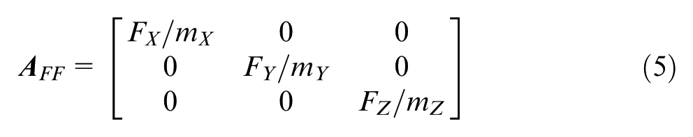
where c is the damping whose value was calculated in previous work and equals 23.7 N s/m. 12 kXX, kYY and kZZ are the robot stiffness of the system in the X, Y and Z directions, respectively. FX, FY and FZ are the force components in the X, Y and Z directions, respectively. ωnX, ωnY and ωnZ are the natural frequency in the X, Y and Z directions, respectively. ςX, ςY and ςZ are the damping ratio in the X, Y and Z directions, respectively. mX, mY and mZ are the equivalent mass in the X, Y and Z directions, respectively. Known from the equivalent system (Figure 1), the equivalent mass for each direction can usually be assumed the same, that is, m = mX = mY = mZ. In this case, the transformation equals the rotation of the coordinate frame, and the uncoupled principal directions are perpendicular to each other.
It is seen from equation (2) that the key for guaranteeing the accuracy of the FE simulation is how to confirm the robot stiffness, the frequency matrix and the equivalent mass. Hence, a stiffness identification and modal test of the robotic boring system should be conducted. Once the robot stiffness and natural frequency are known, the equivalent mass can be obtained via equation (3). After that, ςx, ςy and ςz in
Stiffness identification and modal test
Stiffness identification
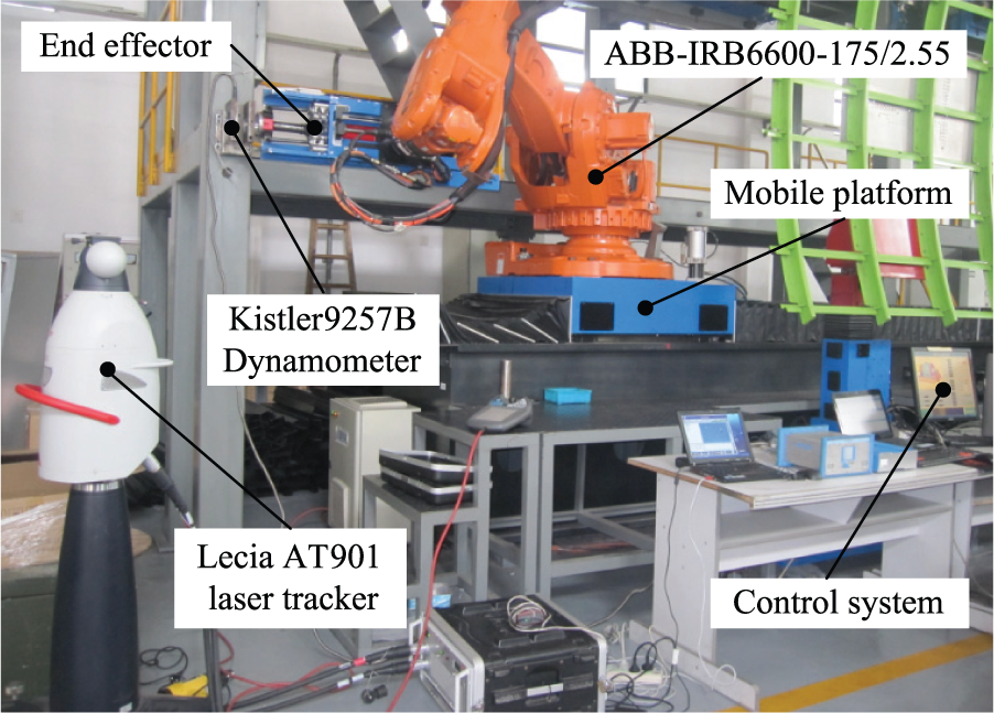
The stiffness identification experiment was conducted to obtain the stiffness matrix of the system as shown in Figure 2. The robot used in the experiment is ABB IRB 6600-175/2.55 and its working joint angle is θ1 = −48.38, θ2 = 54.82, θ3 = 6.86, θ4 = −54.16, θ5 = 107.43 and θ6 = −21.95. A Kistler 9257B dynamometer was used to measure the force resulting from the foot pressure on the workpiece surface. Three reflectors were installed at the end of the flange. A Leica AT901 laser tracker was used to measure the coordinate values of the three reflectors. Keeping the same end-effector posture, a total of six random robot postures, as shown in Table 1, were selected for the experiment. The foot pressure value P ranged from 0, 0.3, 0.4, 0.5 to 0.6 MPa in each posture test. Displacements when the foot pressure P equals 0.3, 0.4, 0.5, 0.6 MPa can be obtained by comparing their coordinate values with that when P equals 0 MPa. According to the D-H method,
13
the kinematics model of the robot is established, as shown in Figure 3. Based on the kinematics model and robot joint angles, the Jacobian matrix
Robot stiffness identification experiment.
Six different postures of the robot.
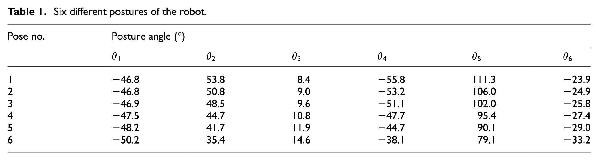
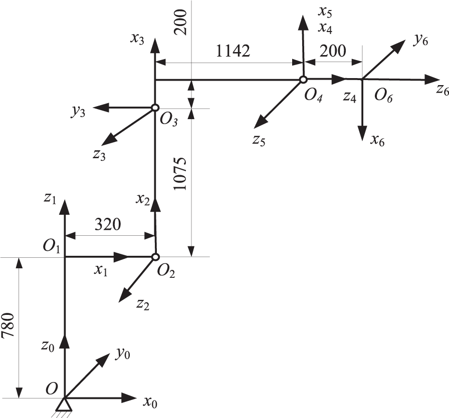
ABB IRB 6600-175/2.55 robot kinematics model.
For industrial robot, the Cartesian stiffness matrix

where

where kθi is the ith joint stiffness of the robot. When a generalized force
where
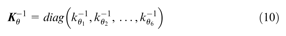
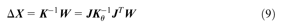
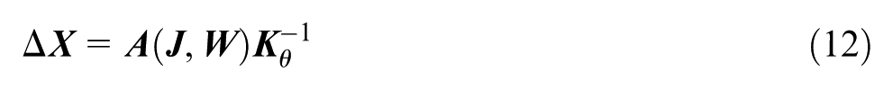
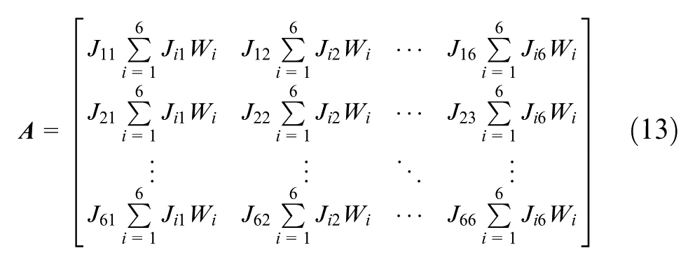
Substitute equation (10) into equation (9), and then, Δ
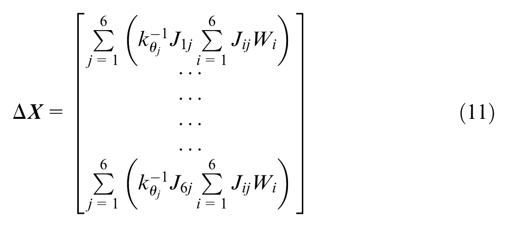
where Jij is the ith row jth column component of
If only one test is done,
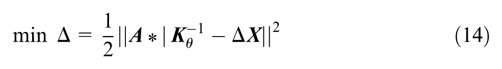
The value of
where

Modal test
As shown in Figure 4, a modal test 16 was performed to obtain the natural frequency of the system. The robot and its joint angles are the same as in the experiment of stiffness identification. In the test, the B&K PULSE testing analysis software was adopted to identify modal parameters. The B&K 3053-B-12 data acquisition card was used to acquire data transformed by a signal process module. Seven accelerometers evenly distributed on the robotic boring system were adopted to collect vibration signals. A force hammer was used to hit measuring point (in total seven points) on the robotic boring system. For each measuring point, the linear averaging of five hittings was used to increase the signal-to-noise ratio.
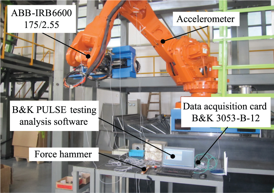
Modal test of robotic boring system.
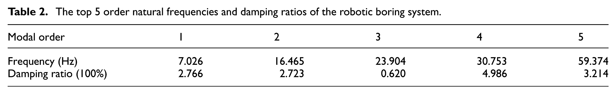
The method of complex mode indication function (CMIF) was used to deal with the experimental data. The estimation method of poly-reference frequency was employed to fit these experimental data, and the largest iteration number of fitting is 40. The frequency response of the robotic boring system was plotted, as shown in Figure 5. The top 5 order natural frequencies and damping ratios are shown in Table 2. The result has been verified by the reality that the resonance occurs when rotational speed equals 400 or 1000 r/min, which is close to the first- and second-order natural frequency, respectively.
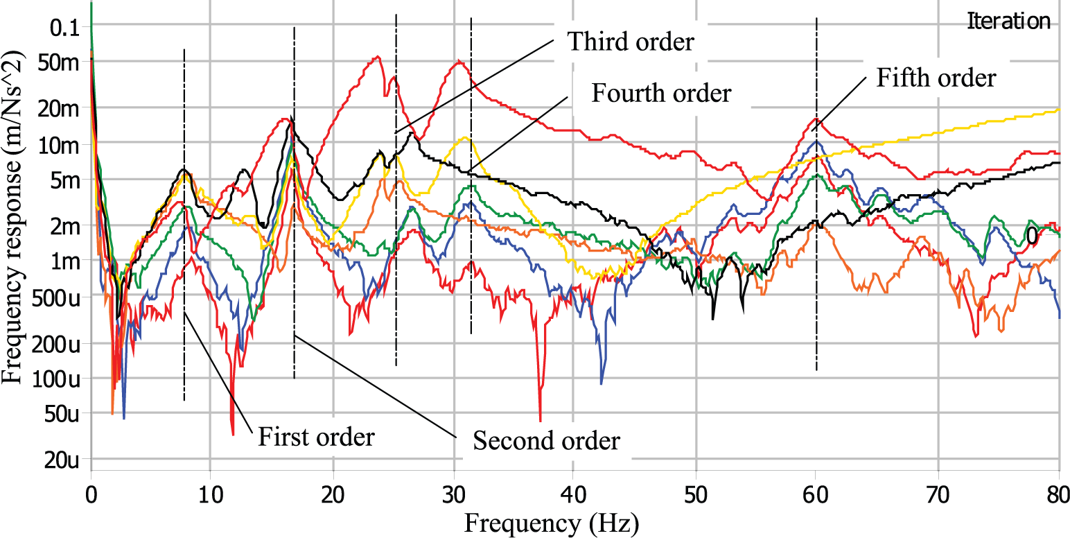
Frequency response of the robotic boring system.
The top 5 order natural frequencies and damping ratios of the robotic boring system.
FE simulation
Modeling and simulation
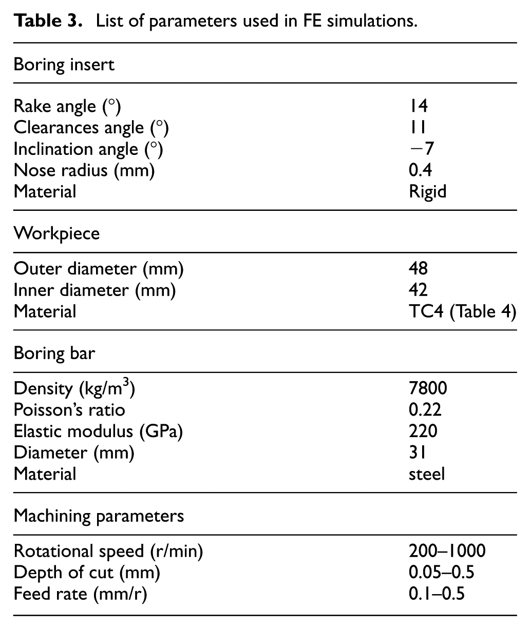
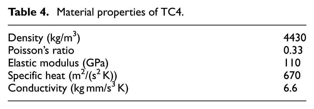
An equivalent 3D FE model of the robotic boring was established in ABAQUS/Explicit software, as shown in Figure 6. All the parameters used in the FE simulation are listed in Table 3. In order to be able to make a comparison between simulation and experiment, the simulation parameters are chosen to be similar to the experimental conditions. The pressure foot and boring insert were assumed to be a rigid body. The material of the workpiece is TC4, and its material properties are presented in Table 4.
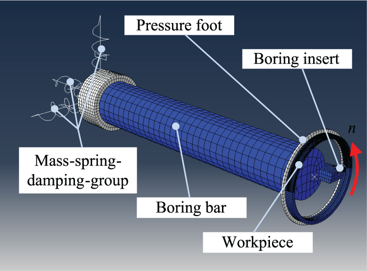
Equivalent 3D FE model of robotic boring.
List of parameters used in FE simulations.
Material properties of TC4.
The influences of the system on the boring process are substituted by a mass–spring–damping group. Three mass–spring–damping units are regarded as the boundary condition to participate in the simulation. Their coefficients used in the simulation originate the previous modal test and stiffness identification. The dynamic explicit arbitrary Lagrangian–Eulerian (ALE) algorithm was adopted to simulate the robotic boring process due to the combined advantages of both Lagrangian and Eulerian methods in large deformation analysis of forming processes.17–19
Material constitutive model and contact modeling
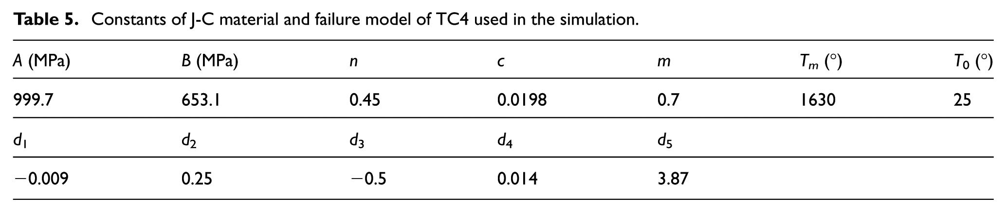
The Johnson–Cook (J-C) material constitutive model was adopted to reflect the mechanical and thermal properties of TC4, and the J-C failure model was used to judge element deletion. 20 Numerous applications have been made of these models because of the simple formulation, the easy calibration and the wide availability of material constants. The J-C failure model in ABAQUS/Explicit is executed as a shear failure mechanism. 21 The constants A, B, C, m, n, Tm and T0 in the J-C material model and failure constants d1, d2, d3, d4 and d5 in the J-C failure model used in the simulation are given by Seo et al. 22 Their values are shown in Table 5.
Constants of J-C material and failure model of TC4 used in the simulation.
The friction along the tool–chip contact interface is not only a complicated process but also seriously different from common frictions due to the high pressure, high temperature and high strain rate. During the machining process, it influences these factors including chip geometries, built-up edge formation, cutting temperature and tool wear. 23 It has been proved that the modified Coulomb friction law is appropriate for cutting simulation and has been utilized successfully in cutting FE simulation by many researchers. Therefore, the modified Coulomb friction law is adopted here to describe the frictional contact between the chip and tool. The friction coefficient µ is assumed to be 0.3 during the simulation. 24
Experimental verification and discussion
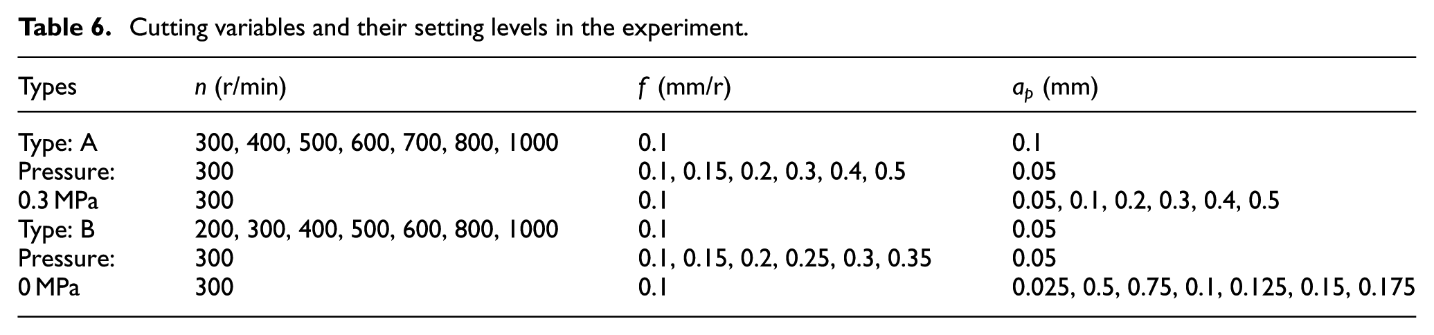
The verification experiment was performed on an ABB IRB 6600-175/2.55 robot with an end-effector cutting titanium alloy TC4. The joint angle of the robot was the same as the previous, and the geometrical parameters of the boring insert used here are consistent with Table 3. The dynamometer Kistler 9257B was used to measure the instantaneous cutting force in the feed, horizontal and vertical directions, whose sampling frequency is 2000 points/s. The grating scale installed on the end-effector was adopted to measure the amplitude in the feed direction with high precision. Since the cutting force could not be directly measured by the dynamometer when a foot pressure P was applied on the workpiece, two kinds of tests (P = 0.3 MPa and P = 0 MPa) were performed for different cutting parameters (rotational speed, feed rate and depth of cut). Their cutting variables and setting levels are the same as the simulation of the robotic boring, which are shown in Table 6.
Cutting variables and their setting levels in the experiment.
The cutting force could not be directly measured by the dynamometer when foot pressure P was applied on the workpiece and the tool displacement can’t be measured by the sensor due to the rotation of the boring bar. Hence, to validate the accuracy of the proposed approach, the cutting force from type B in Table 6 and the amplitude of feed direction from type A in Table 6 were chosen to compare with FE simulation with the same condition, respectively. In Figure 7(a)–(c), the cutting force components measured by the dynamometer in the horizontal, vertical and feed directions at ap = 0.05 mm, f = 0.15 mm/r, n = 300 r/min and P = 0 MPa are presented. It is found that the curves of the cutting force components in the horizontal and vertical directions are close to a sinusoidal shape, and the curve of the cutting force component in the feed direction is almost horizontal. The reason is that there is no vibration occurring during the boring, and the cutting force components follow the rule of stable boring. Figure 7(a1)–(c1) shows a comparison of the cutting force components between the FE simulation and the experiment in half rotating cycle under the same condition. The result reveals that the cutting force components of the FE simulation are in good agreement with experiment.
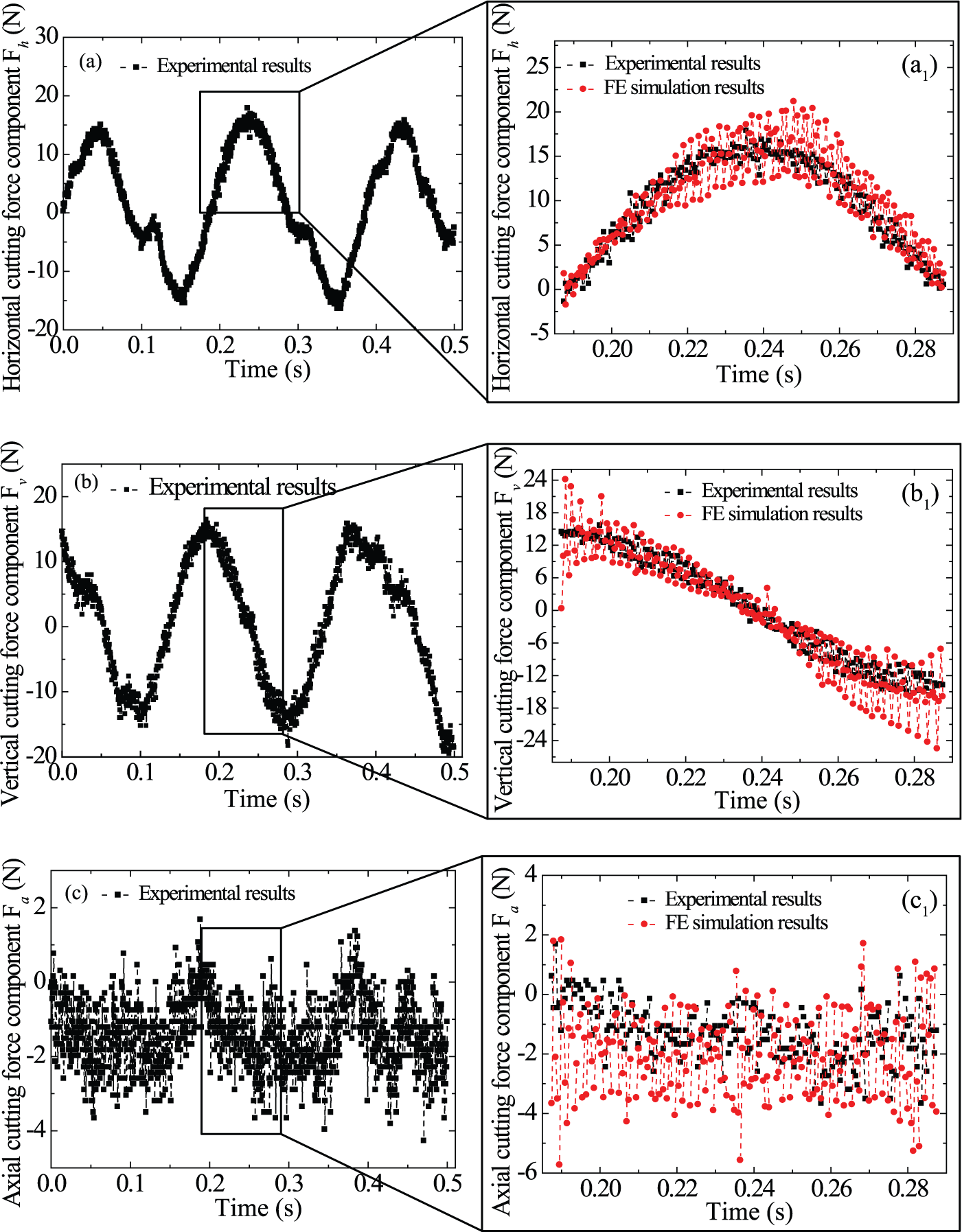
Comparison of the cutting force component between the FE simulation and the boring experiment in the (a) horizontal, (b) vertical and (c) feed directions.
Figure 8 shows a comparison of the amplitude in the feed direction between the FE simulation and the experiment (measured by grating scale) at ap = 0.05 mm, n = 300 r/min, f = 0.5 mm/r and P = 0.3 MPa. From the figure, we can see that their amplitudes are similar, and their shape is close to sinusoidal.
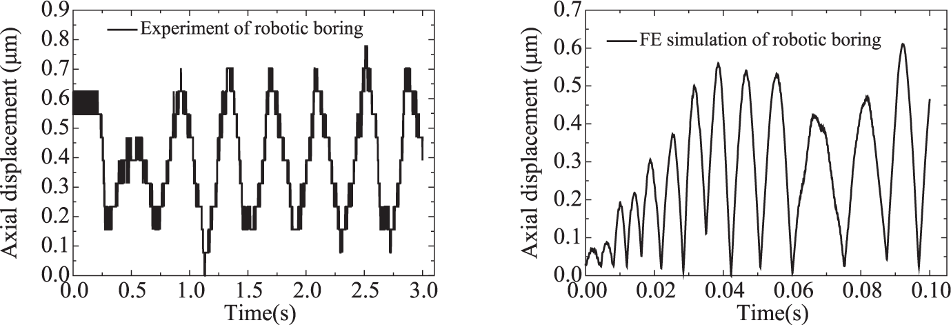
Comparison of the amplitude in the feed direction between the FE simulation and the boring experiment at ap = 0.05 mm, n = 300 r/min, f = 0.5 mm/r and P = 0.3 MPa.
Figure 9 shows a comparison of the average amplitude in the feed direction between the FE simulation and the boring experiment along with depth of cut, feed rate and rotational speed at P = 0.3 MPa. The average amplitudes obtained by the FE simulation and the experiment show a similar trend. Their values increase with the depth of cut and feed rate and almost remain unchanged with the growth of the rotational speed, which indicates that the depth of cut is the main key factor affecting the amplitude. In addition, the FE simulation results show that the amplitudes in the radial direction at P = 0.3 MPa are significantly larger than those at P = 0 MPa. The reason is that the foot pressure increases the stiffness and stability of the robotic boring system.
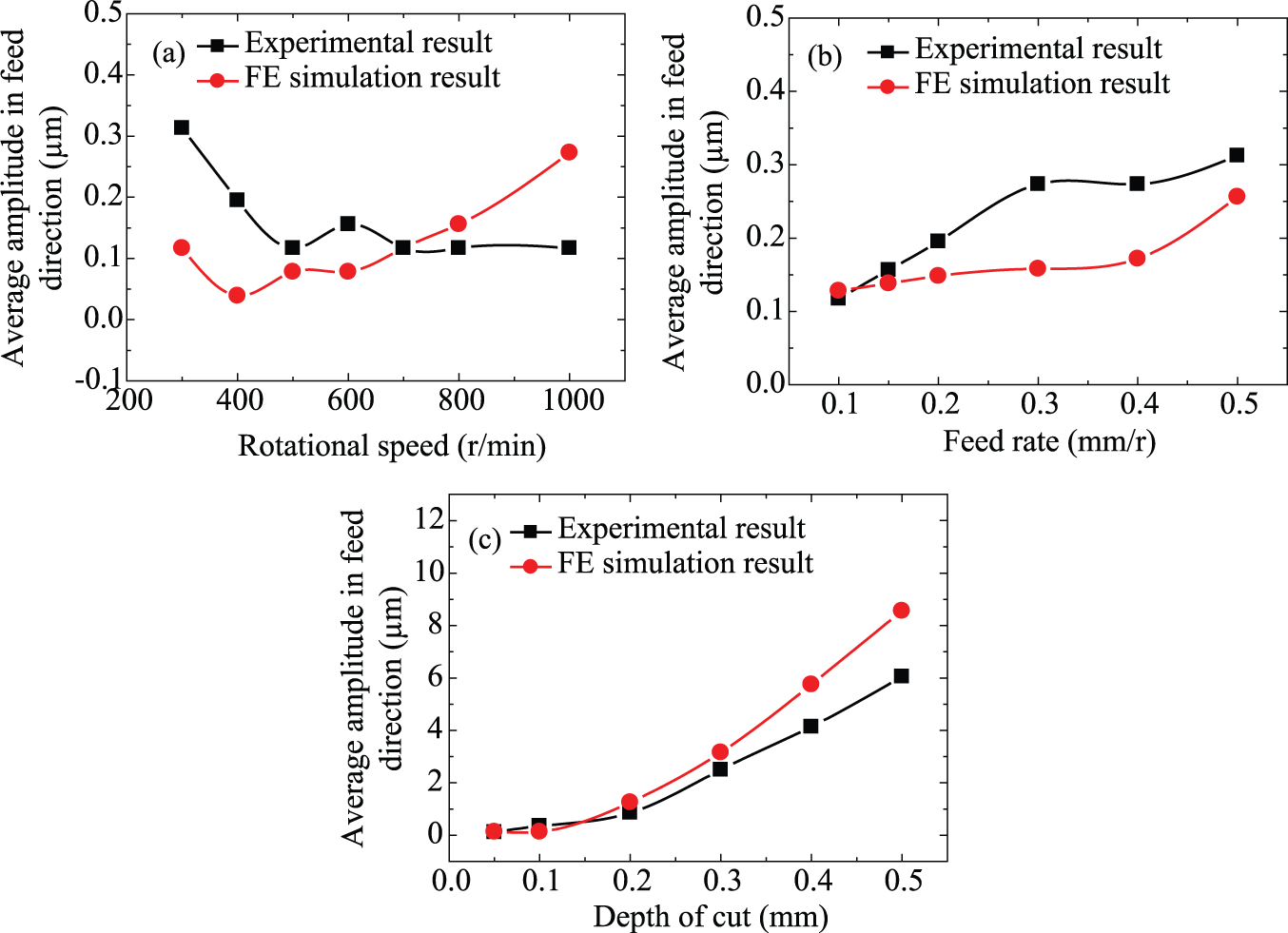
Comparison of the average amplitude in the feed direction from the experiment and FE simulation along with (a) rotational speed, (b) feed rate, (c) depth of cut.
The comparison of the average amplitude of cutting forces along with depth of cut, feed rate and rotational speed is shown in Figure 10. In the figure, the machine tool result was obtained by the method of Atabey et al., 25 which was built based on a machine tool system. It is worth noting that the small black symbols in Figure 10 refer to stable robotic boring, while the larger red symbols represent the vibratory robotic boring. According to the characteristics of robotic boring, the situation of stable and vibratory boring is distinguished by the surface quality of workpiece. When the surface roughness of the workpiece exceeds surface quality requirement, it is considered that vibration occurs, otherwise, the boring is stable. For the robotic machining system, it is easy to see that the average amplitude of cutting forces fluctuate dramatically when vibration occurs. The relative errors between the boring experiment and the FE simulation were also calculated under the condition of stable and vibratory boring, respectively. The maximum and minimum relative errors for the stable case are 15.54% and 3.22%, while their values are 22.56% and 5.61% for the vibratory case. The relative errors revealed that the results of the FE simulation showed good agreement with experiment.
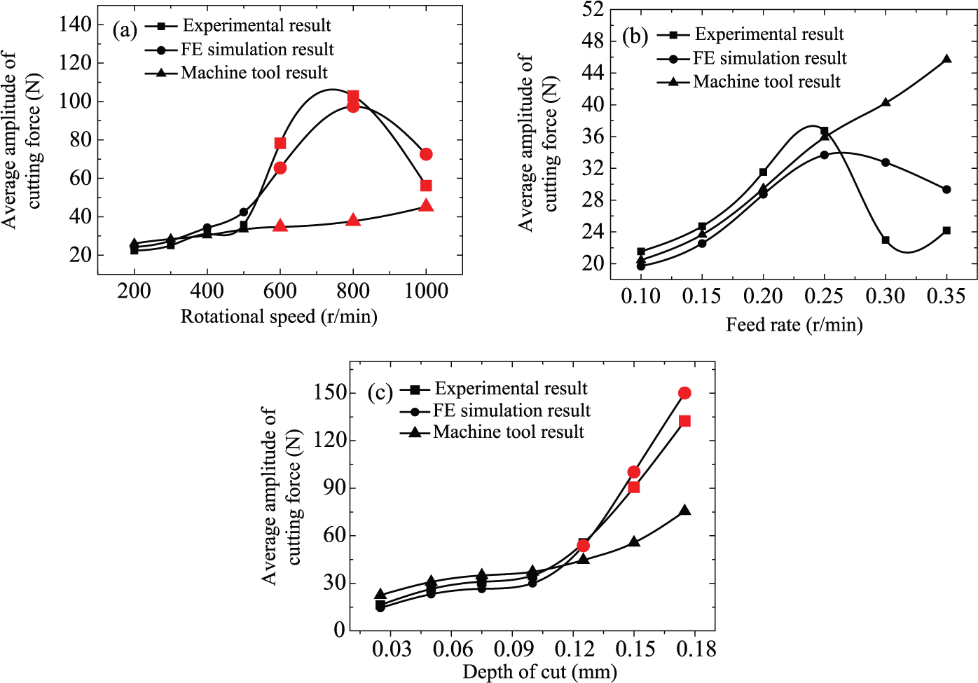
Comparison of average amplitude of the cutting force from the boring experiment and FE simulation, along with (a) rotational speed, (b) feed rate and (c) depth of cut.
Also, as can be seen in Figure 10, the average amplitude of cutting forces obtained from the robot system is different from those obtained from the machine tool system with the growth of feed rate, depth of cut or rotational speed. In n < 500 r/min, ap < 0.1 mm and f < 0.2 mm/r, both cutting forces increase with the growth of depth of cut and feed rate and almost remain unchanged with the increase in rotational speed. When n ≥ 500 r/min, ap ≥ 0.1 mm and f ≥ 0.2 mm/r, the curves of cutting force obtained from the machine tool system remains unchanged, while the corresponding curves of the robotic boring system first increased and then decreased with the growth of rotational speed and depth of cut. The main reason is that the vibration of the robotic boring system was closely related to feed rate, depth of cut and rotational speed.
Some variations that are difficult to measure in the experiment can be obtained more easily in the simulation. Figure 11 shows the variation of the cutting force component and the rotational acceleration for ap = 0.1 mm, n = 300 r/min, f = 0.125 mm/r and P = 0.3 MPa. Due to the effect of foot pressure and the rotation of boring bar, they are hard to obtain using the dynamometer and sensor, respectively. From the picture, it is easy to see that their fluctuations increase quickly with the development of the vibration. Based on these variations, it is beneficial for finding a new method to judge and predict the chatter of a robotic machining system.
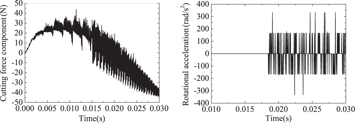
The shape of cutting force component and rotational acceleration obtained from the FE simulation when vibration occurs.
As to cutting force component, the similar phenomenon has also been found from the experiment, as shown in Figure 12(a) and (b). Figure 12(a) shows the cutting force component in the Y direction of stable boring, while Figure 12(b) shows that of vibratory boring. In the picture, it is obvious that the cutting force component varies dramatically when vibration occurs. Their corresponding machined surfaces are illustrated in Figure 12(a1) and (b1). Apparently, the surface quality of stable boring is higher than that of vibration, and the machined surface for vibratory boring shows apparent vibration marks with a high frequency. Since the frequency is not consistent with the periodic frequency of the cutting force, we conclude that it belongs to the chatter whose mechanism will be discussed in the next work. It is also found both in the experiment and the simulation that the vibration is suppressed considerably with the aid of foot pressure. Otherwise, poor results, such as a poor surface finish and reduced tool life, will occur more easily. Particularly, it is expected that this proposed approach can also be used for analogous simulation and stability analysis which considers the effect of the robot system such as robotic drilling.
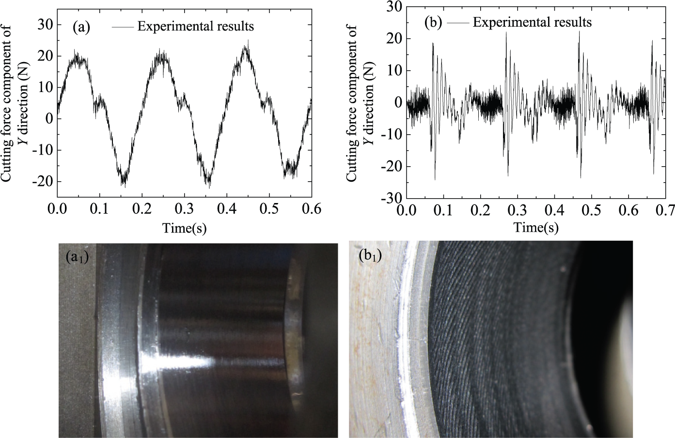
The shape of cutting force component of Y direction and machined surface obtained from the experiment for (a) stable and (b) vibratory borings.
Conclusion
In this article, a new approach based on an equivalent stiffness is proposed to gain a fundamental understanding for the cutting mechanism and vibration performance of a robotic boring system. Based on this proposed approach, the following conclusions are drawn:
The cutting force components and the amplitude in the feed direction obtained from the FE simulation are consistent with those measured by the experiment.
Uniform variation tendency for the experiment and the simulation along with depth of cut, feed rate and rotational speed have been observed.
For stable boring, the maximum and minimum relative errors were calculated as 15.54% and 3.22%, respectively. Similarly, the maximum and minimum relative errors of the vibratory boring were 22.56% and 5.61%, respectively.
Some variations that are difficult to measure in the experiment can be obtained more easily in the simulation. Using these variations, it is beneficial for finding a new method to judge and predict the chatter of a robotic machining system.
In addition, it is expected that this proposed approach can also be used for analogous simulation and stability analysis which considers the effect of the robot system such as robotic drilling.
Footnotes
Declaration of conflicting interests
The author(s) declared no potential conflicts of interest with respect to the research, authorship and/or publication of this article.
Funding
The author(s) disclosed receipt of the following financial support for the research, authorship, and/or publication of this article: This research was supported by the National Natural Science Foundation of China (No. 51575479) and the Science Fund for Creative Research Groups of National Natural Science of Foundation of China (No. 51521064).