
Abstract
Wear rates are rapid when drilling carbon fibre–reinforced plastics/Ti-6Al-4V alloy stacks because of their distinct mechanical properties. Tool wear leads to a high thrust force, thereby reducing the quality of the drilled holes. This article develops a novel mechanistic model for carbon fibre–reinforced plastics/Ti-6Al-4V stacks, which is characterised by the cutting edge radius, to predict the variation of the thrust force when drilling with worn drill bits. Drilling experiments with varying feed rates were performed using carbide twist drill bits. The thrust force and drill edge profile were measured to calibrate and validate the presented model. The edge radius increases with both the cutting distance and number of drilled holes at varying feed rates. It was found that the growth rate of the edge radius increased with the feed rate with identical cutting distances, whereas it decreased slightly with the feed rate when the number of drilled holes was identical. Tool wear reduces the equivalent rake angle of the drill edge, resulting in higher thrust force. The maximum thrust force increases almost linearly with the edge radius of worn drills for both materials. The predicted thrust force curves are in very good agreement with the measured curves during the entire process. Average absolute errors of the maximum thrust force for carbon fibre–reinforced plastics and Ti-6Al-4V alloy are 3.24% and 1.88%, respectively.
Introduction
Thrust force is a key parameter in drilling because it directly affects the quality of a hole. It is influenced by both the cutting parameters and the geometry of the drill bit. The feed rate, drill point, and cutting speed are significant parameters that affect the quality of a hole when drilling titanium alloys, aluminium alloys, and engineering plastics.1,2 To estimate the hole’s defects such as burr, diameter tolerance, and surface roughness, data mining and artificial neural networks have been employed for Ti-6Al-4V alloys and Al 7075-T6.3,4 Typically, thrust force is used to establish prediction models for burr and delamination when drilling metals or composite materials. Previously, a burr formation model was developed to predict burr height according to the thrust force distributed along the material in front of the drill. 5 To predict burr type, an analytical model based on slip-planes theory was proposed in which the thrust force was a crucial input parameter. 6 Additionally, the size of the delamination zone is related to the thrust force during drilling composite laminates.7,8 The first model to determine the critical thrust force, below which no delamination occurs, was developed using a fracture mechanics approach. 9 When the thrust force was over a critical value, an approximate positive linear correlation between delamination and thrust force was observed. 10 Subsequently, the model was extended to analyse the delamination caused by a worn twist drill 11 and special drill bits. 12 During drilling the metal/metal stack, interlayer burr size increases with the growth of the gap, which is induced by the interlayer thrust force. 13 Collectively, these results imply that modelling thrust force is a decisive step towards controlling the occurrence of defects when drilling monolayer and multilayer structures.
Carbon fibre–reinforced plastics (CFRPs) have been employed broadly in the aeronautical industry because of their high strength-to-weight ratio, high stiffness-to-weight ratio, and high corrosion resistance. 14 By comparison, Ti-6Al-4V alloy has a higher corrosion resistance and strength than CFRPs, but it has a lower strength-to-weight ratio. Hybrid structures of CFRPs and titanium stacks provide enhanced material properties, which have been increasingly employed because of fuel efficiency and lifecycle requirements.15,16 Fastener holes must be drilled through composite/titanium stacks instead of drilling through each layer separately to minimise positional errors and to obtain tight tolerances during assembly processes. 17 A hole diameter of 6.38 ± 0.04 mm is the typical tolerance for aerospace applications, 18 and the tolerance grade for aeronautical applications is approximately IT6-IT8. 19 Different mechanical and thermal properties for the two materials in CFRP/Ti-6Al-4V stacks result in rapid tool wear during the drilling process. 20 High speed cutting could reduce the delamination damage with increased material removal,21,22 although tool wear enlarges the delamination areas when drilling composite laminates. 23 A strong correlation between tool wear and thrust force has demonstrated the potential use of force measurements for real-time assessments of tool wear when drilling metals or composite materials.24,25 Tool wear results in a significant increase in thrust force when drilling metallic–composite stacks; 20 thus, it is not neglected when predicting the thrust force. In this regard, it is desirable to understand and model the effect of tool wear on thrust force in CFRP/Ti-6Al-4V stacks.
In metal machining, tool wear is commonly characterised by the average flank wear width. In drilling titanium alloys, flank wear increases because of increasing the feed rate and the thrust force. 26 A large helix angle could assist in slowing tool wear, 27 and drill materials with higher hardness and higher density are more wear resistant. 28 However, the flank wear criterion is not relevant when machining CFRPs. Indeed, the primary wear type when drilling composites is referred to as edge wear because the build-up edge on the rake face does not exist as a result of the brittle nature of CFRPs. 29 A new wear characteristic, named cutting edge rounding (CER), has been proposed as a measure of drill bit bluntness when drilling CFRPs instead of the flank wear width. 30 Comparison of edge rounding wear when drilling CFRP/Ti-6Al-4V stacks with that in drilling CFRP-only and titanium-only indicated that tool wear primarily came from the CFRPs. 31 Carbide drills have high chemical affinity to titanium but low chemical affinity to CFRPs. Therefore, adhesion of titanium and abrasion by carbon fibres were identified as the dominant wear mechanisms when drilling CFRP/Ti-6Al-4V stacks. 32 The experimental results showed that wear progressed almost equally on the rake and flank faces at low spindle speeds, resulting in a round cutting edge.
Some efforts have been devoted to modelling the effect of tool wear on the thrust force for both metals and composites. An empirical formula between the average thrust force and flank wear was established through statistical analysis of experimental data. 33 A phenomenological model of axial load was extended to consider the tool wear represented by the cutting edge acuity for the CFRP drilling process. 34 Additionally, a multiple regression model was proposed to correlate thrust force with tool wear represented by wear mass when drilling fibre-reinforced composites. 35 A linear relationship was found between the thrust force and wear mass, with a slope of 12.8.
The models mentioned above focus on predicting the maximum thrust force of worn drill bits when drilling single-layer plates. This article aims to develop a novel mechanistic model for worn drills that can predict the variation of thrust force with machining time when drilling CFRP/Ti-6Al-4V stacks. The round edge radius was chosen as the wear criterion because of its capacity to accurately reflect the change in geometry of drill edges compared with the flank wear width or wear mass. The development of such a mechanistic model contributes to the prediction of varying thrust forces of worn drills for multilayer structures. Moreover, this research will assist in understanding the influence of tool wear better and in determining when to change the tool to avoid machining defects in composite/metal stacks.
This article develops a mechanistic model to predict the variation of thrust force with machining time for worn drill bits with round edge when drilling composite stacks. Subsequently, the experimental thrust force and edge radius were used to evaluate the proposed model. Finally, the influences of drill parameters on the edge radius and thrust force were discussed in the context of the proposed model.
Model derivation
Cutting angles along drill edges
The cutting edges of twist drills are mainly composed of the chisel edge and cutting lips. Five parameters are employed to define the geometrical features of the cutting edges, including the point angle (2p), helix angle (θ), web thickness (2ω), chisel angle (ψ), and radius of the chisel edge (Rch). Cutting angles such as the rake angle, relief angle, and inclination angle for a fresh drill bit vary along the drill edges with radius distance (r). Notably, these angles mainly determine the cutting forces. The drill edges become gradually rounded when drilling CFRP/Ti-6Al-4V stacks. The radius of the rounded edge, defined as the edge radius (rβ), is proposed to quantitatively describe the worn drill geometry. The geometry of a worn drill edge is shown in Figure 1. Element M is an arbitrary point on the drill edge, whose radius distance is r.
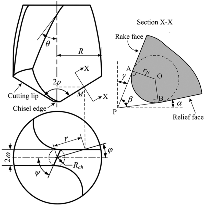
Geometry of a worn drill edge.
The rake angle (γ) is the representative angle used to describe the orientation of the rake face. The rake angle on the chisel edge is shown in equation (1) 36

In contrast, the rake angle on the cutting lip is expressed in equation (2)
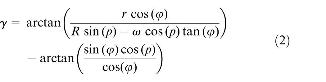
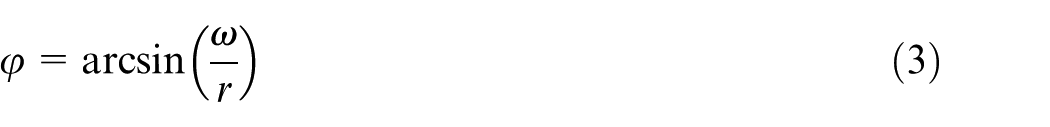
where R is the drill radius and φ is the web angle defined by equation (3)
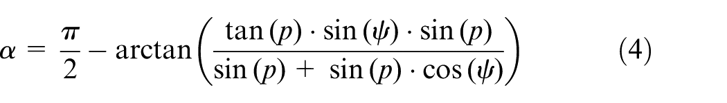
The relief (or clearance) angle (α) describes the orientation of the relief face. The relief angle on the chisel edge is expressed in equation (4) 37
In contrast, the relief angle on the cutting lip is expressed in equation (5)
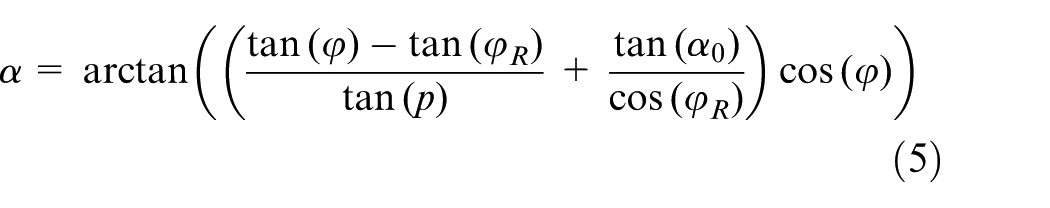
where α0 is the reference relief angle defined at the outermost point on the cutting lip and φR is the web angle at radius distance R.
The wedge angle (β) describes the rake face angle relative to the relief angle (Figure 1) and can be written as equation (6)
The cutting lip geometry and its cutting angles are shown in Figure 2. The geometrical parameters used to calculate cutting angles are listed in section ‘Tool, workpiece, and equipment’. As observed from Figure 2, the rake angle varies from negative to positive values, whereas the relief angle decreases until it equals the reference value α0. The wedge angle decreases as the radius distance (r) increases, while the cutting angles along the chisel edge remain constant.
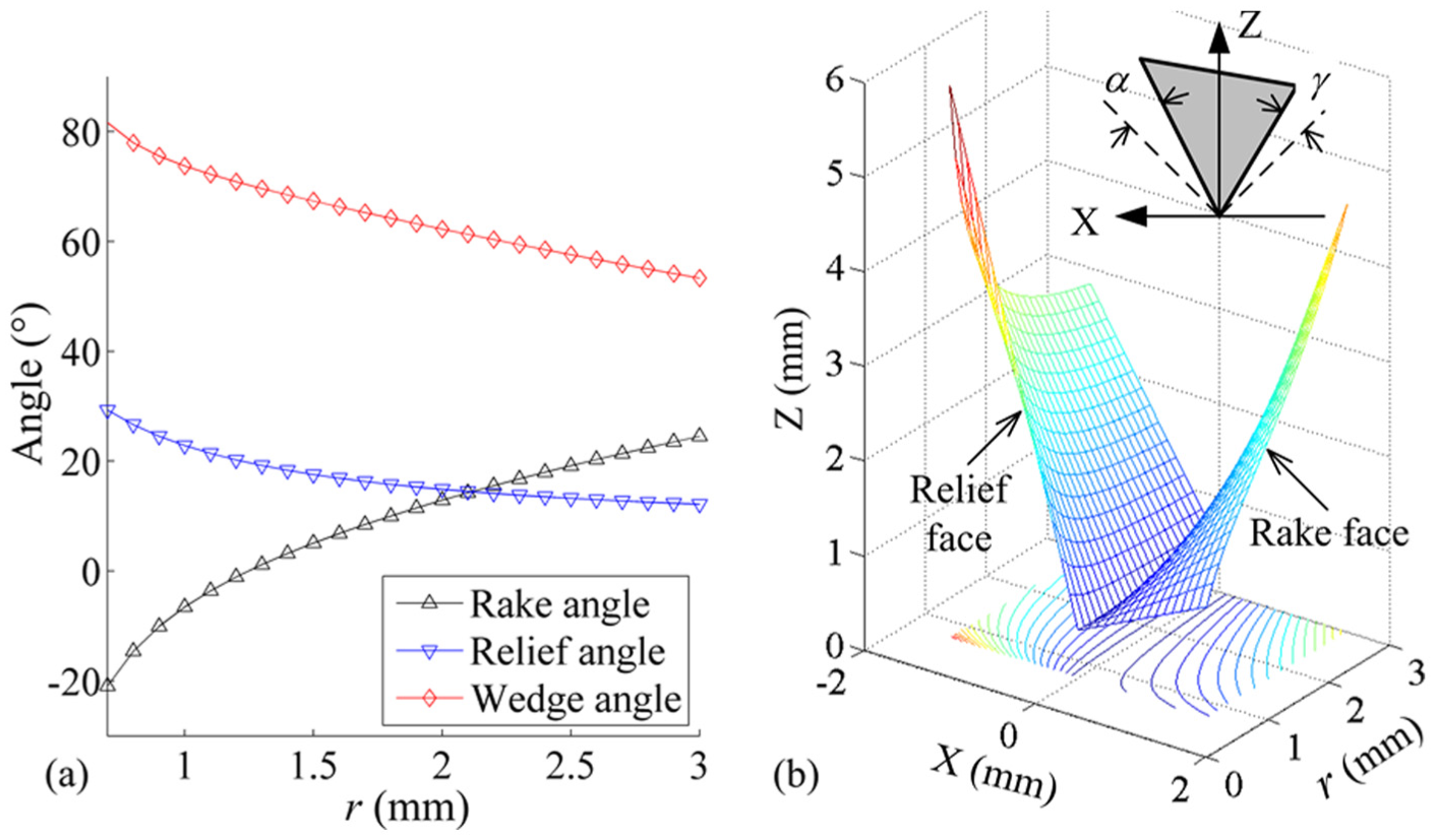
Cutting lip of drill bits (a) Cutting angles. (b) Geometry.
Edge radius of the worn drill
According to Archard’s model, the volumetric wear of a drill bit is proportional to the cutting distance and contact force. The volumetric wear of element M, whose radius distance is r as shown in Figure 1, can be calculated using equation (7) 34

where kw is the wear coefficient, dF is the contact force, and s is the cutting distance.
The cutting speed in the feed direction is negligible compared with the rotational speed during the drilling process. Thus, the cutting distance of element M can be expressed as equation (8)
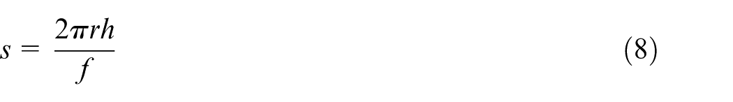
where h is the drilled depth.
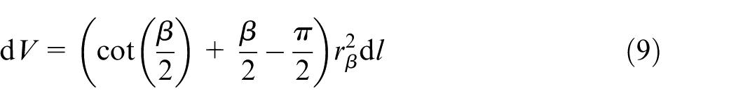
As shown in Figure 1, the worn part area equals the AOBP area minus AOB. The AOBP area equals double the area of the right triangle PAO or PBO. The volume dV equals the production of the wear area and the cutting element width (dl), as shown in equation (9)
The cutting element width M is expressed in equation (10) as 31
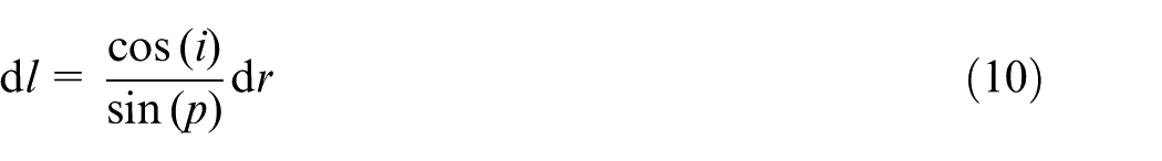
where p is half of the point angle and i is the inclination angle, which can be expressed in equation (11) 31

Combining equations (7) and (9) gives the equation to calculate the edge radius (equation (12)
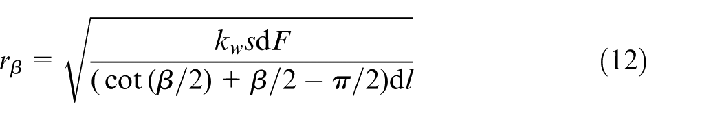
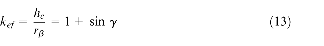
The geometries of the cutting elements at r = Rch and r = R on the cutting lips are shown in Figure 3. For cutting elements with varying rake angles, the contact lengths in the feed direction (hc) are different, although they have the same edge radius. The effective contact rate (kef) is defined in equation (13) as the ratio of the contact length hc to the edge radius
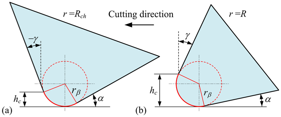
Contact length in the feed direction of the cutting elements at : (a) r = Rch, (b) r = R
Thrust force on worn edges
As a drill bit rotates around and feeds along the drill axis, material is removed primarily by the two cutting lips. Cutting forces consist of the force acting on the rake face and the force acting on the cutting edges. 38 In addition to the shearing process, a second mechanism, termed the ploughing process, plays an important role as material is removed with a rounded edge. The material before the rake face is sheared forming chips during the shearing process, whereas the material around the cutting edge is deformed elastically and plastically in the ploughing process. Accordingly, the cutting forces of a worn drill consist of a shearing force (Fsh) and a ploughing force (Fpl). Figure 4 illustrates the cutting forces acting on a cutting element of a worn drill.
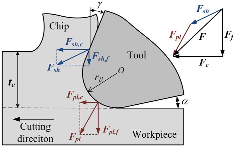
Cutting forces acting on a cutting element with a round edge. 38
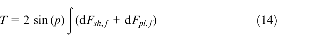
It is assumed that each point on the drill edge cuts orthogonally. The total force F is decomposed into two mutually perpendicular forces. One force cuts in a direction termed as Fc, and the other force is in the feed direction and is termed as Ff. The feed force (Ff) equals the sum of the shearing force in the feed direction (dFsh,f) and the ploughing force in the feed direction (dFpl,f). Additionally, the feed force can be resolved into two components in the perpendicular and parallel directions to the drill axis. The parallel components are summed for all elements of the cutting edges to obtain the thrust force (T), as shown in equation (14)
For each cutting element, the shearing force in the feed direction is assumed to be proportional to the uncut chip area (dAc), which can be expressed as equation (15)

where f is the feed rate (mm/rev) and kc is the specific cutting pressure. Since the cutting velocity has little effect on the thrust force, the specific cutting pressure depends mostly on the uncut chip thickness (tc) and rake angle (γ). The feed rate is proportional to the uncut chip thickness during the drilling process. Thus, the specific cutting pressure (kc) can be expressed as equation (16)

where kc1, kc2, and a are coefficients of the specific cutting pressure, which must be calibrated experimentally.
Fitting results have shown that the ploughing force in the feed direction has a linear relationship with the edge radius. 38 Accordingly, the elementary ploughing force in the feed direction can be expressed as equation (17)

where kef is the effective contact rate defined in equation (13) and Aβ and Bβ are coefficients that must be calibrated experimentally.
In the drilling process, the cutting speed increases with radius distance, whereas the cutting force decreases with an increase in radius distance because of increases in the rake angle. 37 Thus, the variation of the cutting temperature along the drill edge is not as significant as the cutting speed. Experimental results show that the temperature profiles are nearly insensitive during drilling. 39 Therefore, the drill edge cutting temperatures can be assumed to be uniform. Since the cutting temperature and properties of a workpiece material are similar, the entire drill edge experiences a similar wear process. The wear coefficient described in equation (7) depends on the temperature and material properties of the tool–workpiece transition zone. Thus, the wear coefficient is constant along the entire drill edge. Edge radius along drill edge can be obtained if the value at the drill’s periphery (rβ0) is known. By substituting equations (8) and (15) into equation (12), the ratio of the edge radius to its value at the periphery can be expressed as equation (18)
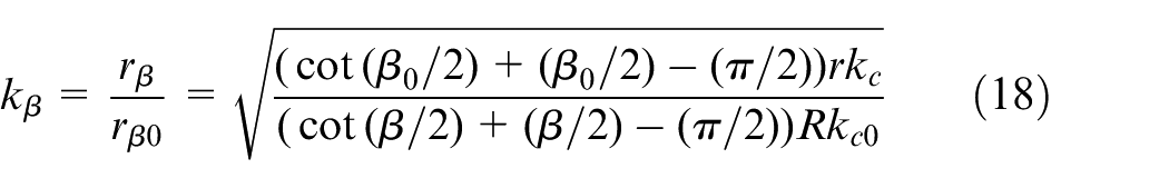
where β0 and kc0 are the values at the periphery.
Substituting equations (13), (15), (17), and (18) into equation (14) and rearranging allows the thrust force to be written as equation (19)

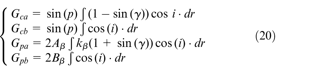
where Gca, Gcb, Gpa, and Gpb are the integral terms given in equation (20)
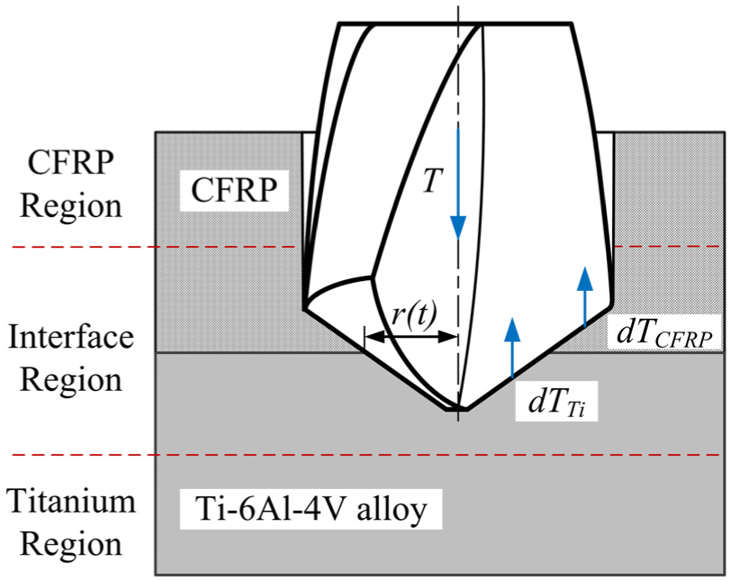
The drilling process of CFRP/Ti-6Al-4V stacks can be divided into three stages according to the contact material of the drill edges, as shown in Figure 5. The drill edges cut CFRP or Ti-6Al-4V alloy only in the CFRP or titanium regions, whereas they cut CFRP and Ti-6Al-4V alloy simultaneously in the interface region. The cutting forces in the interface region can be obtained by summing all elementary forces acting on CFRP and Ti-6Al-4V alloy. The thrust force at time t in the interface region can then be expressed as equation (21)
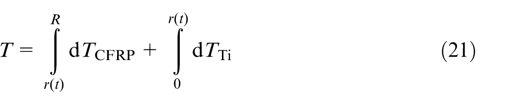
where r(t) is the maximum radius distance in the Ti-6Al-4V alloy at time t. The limit of integration r(t) is associated with the drill geometry and the cutting conditions, as shown in equation (22)
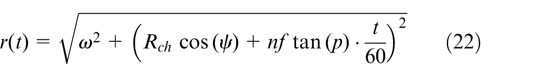
where n is the spindle speed (rev/min).
Stages of the drilling process of CFRP/Ti-6Al-4V stacks.
To clearly show the steps to derive the model, a flowchart is presented in Figure 6. First, the cutting edges of the worn drill are divided into the cutting elements whose cutting angles and edge radii are mathematically described. Then, the shearing and ploughing forces acting on the cutting elements are calculated using coefficients calibrated from experimental data (Table 3). Finally, the variation of the thrust force for the worn drill is obtained by summing the forces on all of the cutting elements.
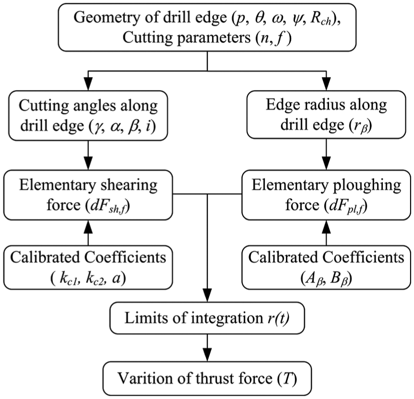
Flowchart of the model derivation.
Experimental procedure
Tool, workpiece, and equipment
A twist drill with a straight (uncoated) cutting edge was used in this study. The tool was manufactured by DaShuo Ltd and was composed of cemented carbide. The geometric parameters include a 6.0 mm diameter, 118° point angle, 25° helix angle, 54° chisel edge angle, 12° reference relief angle, and 0.97 mm web thickness. The reference relief angle is measured at the outermost point of the drill.
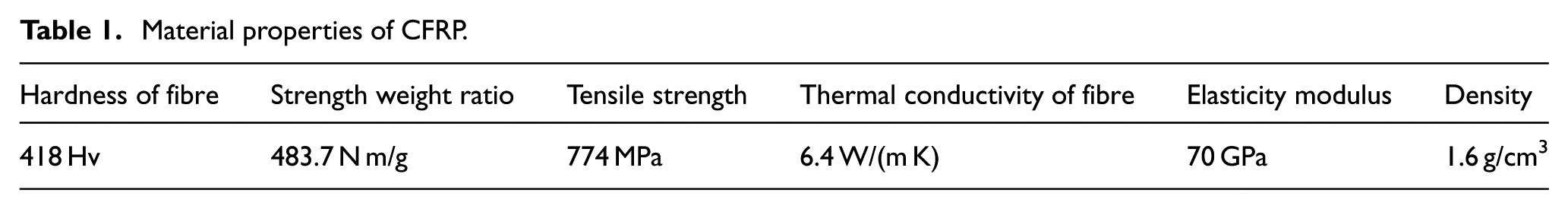
Among the fibre-reinforced composites, CFRP is the most common material used in hybrid structures because of their excellent mechanical properties. The CFRP used in this study is woven-ply, which possesses near maximum stiffness and strength along both directions. 14 The woven CFRP consists of fibre (T300) and matrix (epoxy resin) with 40% resin content. The material properties of the woven CFRP are listed in Table 1.
Material properties of CFRP.
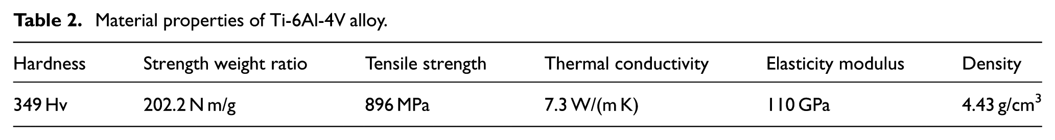
The workpieces are composed of woven CFRP and Ti-6Al-4V alloy. Plates of the two materials were cut into small strips that were 30 mm wide and 120 mm long. A CFRP strip with a 5.3 mm thickness was placed on top of a titanium strip with a 4.5 mm thickness. The materials were then joined mechanically using stainless steel bolts. The material properties of the Ti-6Al-4V alloy are given in Table 2.
Material properties of Ti-6Al-4V alloy.
The drilling experiments were conducted on a computer numerical control (CNC) milling machine (XKN713). To avoid the influence of deflection on the drilling process, a backing plate with 8 mm holes was placed under the workpiece. The thrust force during the drilling process was recorded using a dynamometer (Kistler 9125A) that was located under the backing plate. Combined with a charge amplifier (Kistler 5237), the force signals were collected and saved with a data recorder (HBM GEN2i). For clarity, the experimental design is shown in Figure 7.
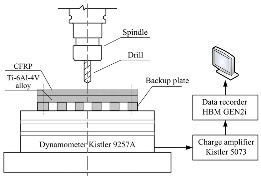
Design of the drilling experiments.
Test methodology
A series of experiments was performed to investigate the effect of the edge radius and feed rate on the thrust force. The selected feed rates were 0.06, 0.09, and 0.12 mm/rev. For each feed rate, 80 holes were drilled with a new drill bit. The edge radius of each drill was measured before each experiment and after every 16 holes drilled. The two stacked materials were drilled with the same parameters. We note that the high temperatures generated when drilling titanium at high speed will destroy the CFRP at the stack interface. 17 Therefore, a low spindle speed should be used when drilling CFRP/Ti-6Al-4V stacks. Spindle speed has little influence on the thrust force, but it significantly affects cutting temperature, especially when drilling Ti-6Al-4V alloys. 14 This study focuses on the influence of tool wear on thrust force, and the cutting temperature is not considered. For this reason, the spindle speed was not selected as an input parameter for the predictive models. Instead, the spindle speed was held constant at 1000 rev/min in all experiments. The cutting speed varies with radius distance, whose maximum value is 0.26 m/s at the periphery.
To obtain the edge radius of the worn drill, an optical three-dimensional (3D) micro-measurement device (InfiniteForce IFM G4) was used to measure the drill edges (Figure 8(a)). The measured data (as a point-cloud) were processed to generate a 3D topography of the cutting edge (Figure 8(b)). The profile of the peripheral worn edge was obtained by cutting the topography with a plane perpendicular to the cutting edge (Figure 8(c)). The profile data were then used to calculate the edge radius.
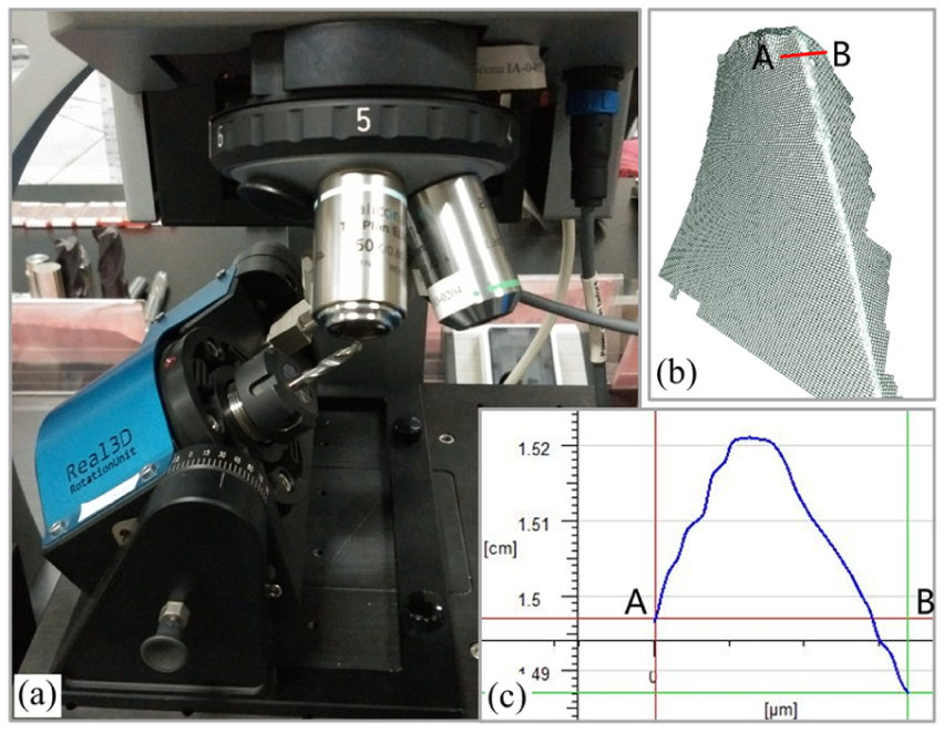
Measurement of the peripheral edge profile. (a) Micro-measurement device. (b) Topography of cutting edge. (c) Profile of cutting edge.
Determination of the coefficients
The edge profile is rotated to be symmetric around the vertical axis. Points within theoretical straight lines are chosen to draw a circle that fits the measured profile as close as possible. In addition, the circle must also be tangent to both straight fitting lines. The radius of the fitted circle is the round edge radius. The round edge profiles and their fitted circles for a different number of drilled holes are shown in Figure 9 for a 0.09 mm/rev feed rate. The edge radius is not constant along the cutting edge, and the radius is measured at a distance of 2.9 mm.
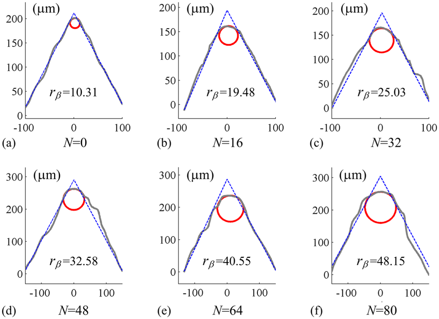
Edge profile and fitted circle: (a) N = 0, (b) N = 16, (c) N = 32, (d) N = 48, (e) N = 64, and (f) N = 80.
The statistical method ‘moving average’ is used to smooth the thrust force signals. Figure 10 shows the maximum forces (Tmax) chosen from the smoothed curves in the CFRP and titanium region. Polynomial regression lines show the variation trends of force Tmax (Figure 10). The average absolute deviation (Δ) of Tmax is calculated using equation (23), and the average deviations Δ are 12.34% and 0.85% for CFRP and Ti-6Al-4V alloy, respectively. Although the maximum forces for CFRP are clearly distinct, the fitting lines have the same trend as that of Ti-6Al-4V alloy. The maximum forces for CFRP at varying feed rates coincide with each other because they are discrete. To show Tmax of CFRP clearly, the maximum thrust forces for each feed rate are presented separately in Figure 10(a)–(c)
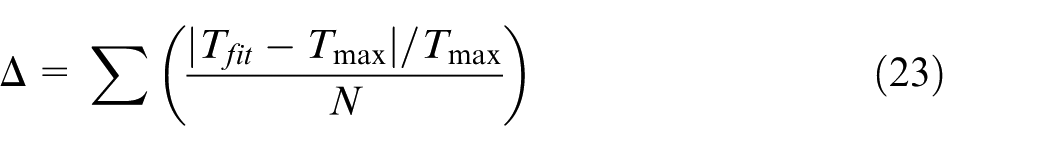
where Tfit is the fitted value of the maximum thrust force and N is the number of drilled holes.
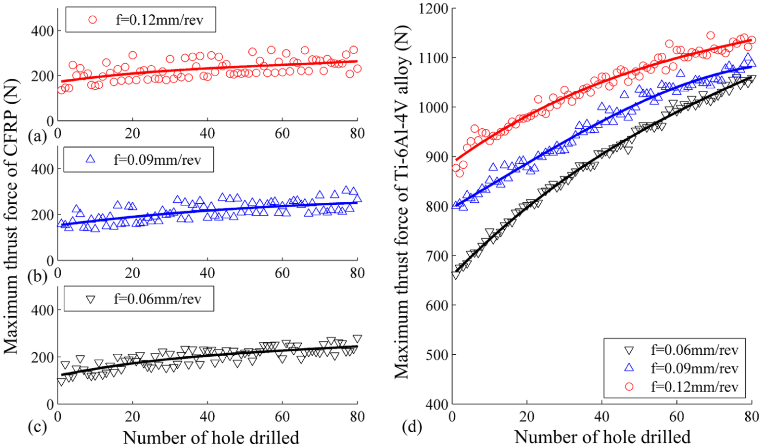
Maximum thrust forces versus number of drilled holes: (a) drilling CFRP at f=0.12mm/rev, (b) drilling CFRP at f=0.09mm/rev, (c) drilling CFRP at f=0.06mm/rev, (d) drilling Ti-6Al-4V alloy.
Figure 11(a) and (b) represents the variation of the fitted maximum forces with the edge radius at different feed rates. Since the edge radius of a fresh drill bit is greater than zero, the shearing force Fsh,f is obtained by linear extrapolation of thrust force. The force Fsh,f equals the vertical intercept of the fitted line where the edge radius is zero. The ploughing force Fpl,f is determined by subtracting the shearing force from the force Tfit. In addition, linear fitting was also used to obtain the force Fpl,f. The coefficients of determination (R2) are calculated and shown in Figure 11(c) and (d). In section ‘Model evaluation’, the causes of the increases in thrust force and ploughing force with the edge radius are presented.
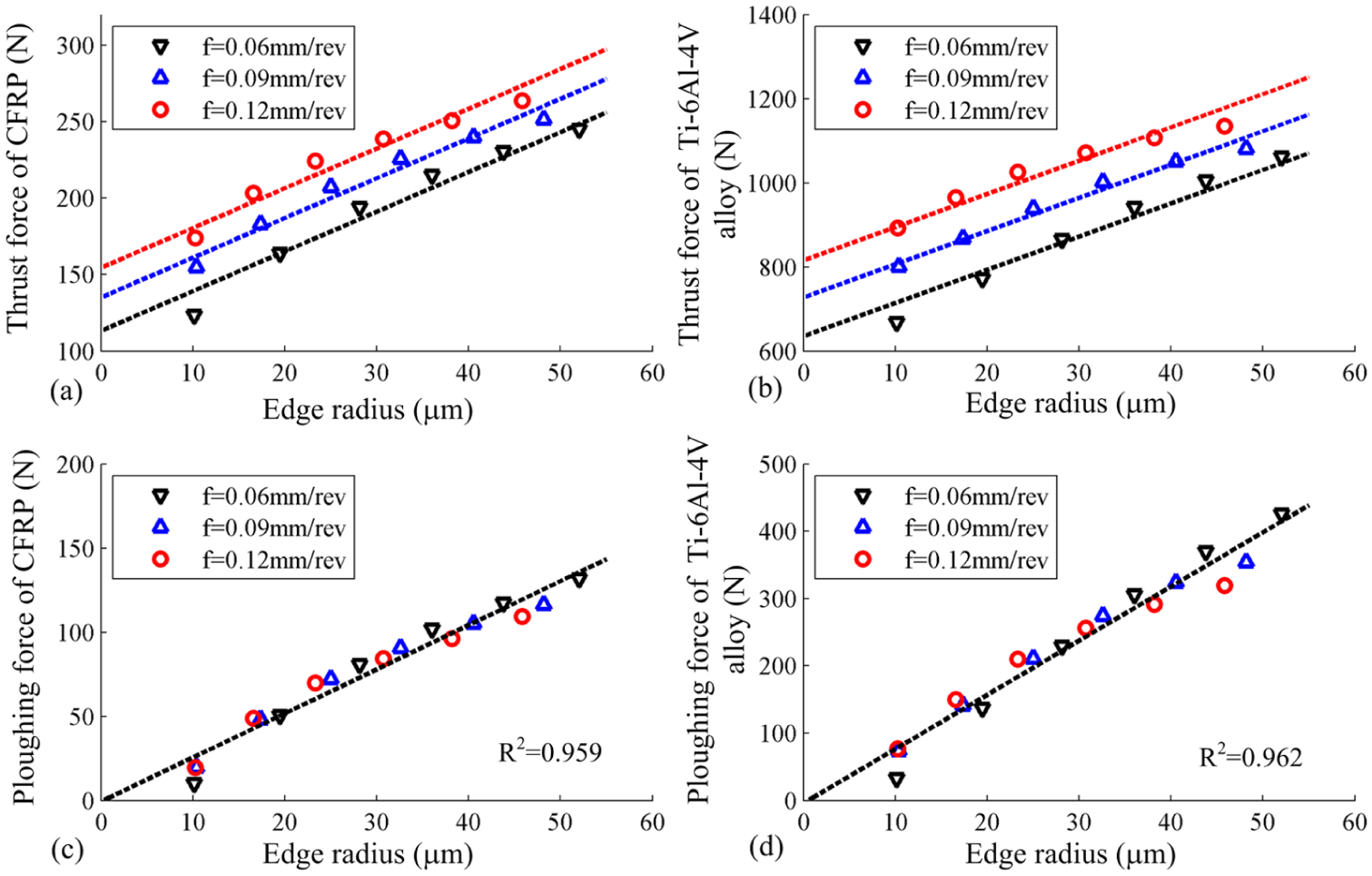
Cutting forces versus edge radius: (a) thrust force of CFRP, (b) thrust force of Ti-6Al-4V alloy, (c) ploughing force of CFRP, (d) ploughing force of i-6Al-4V alloy.
The coefficients of the proposed model are calibrated by employing equations (19) and (20) based on the shearing and ploughing forces. The calibrated values are listed in Table 3. For the chisel edge, the mechanism to remove material is different than that for the cutting lips. Therefore, coefficient kc0 is replaced with kc1 and kc2 is set to zero.
Calibrated coefficients.
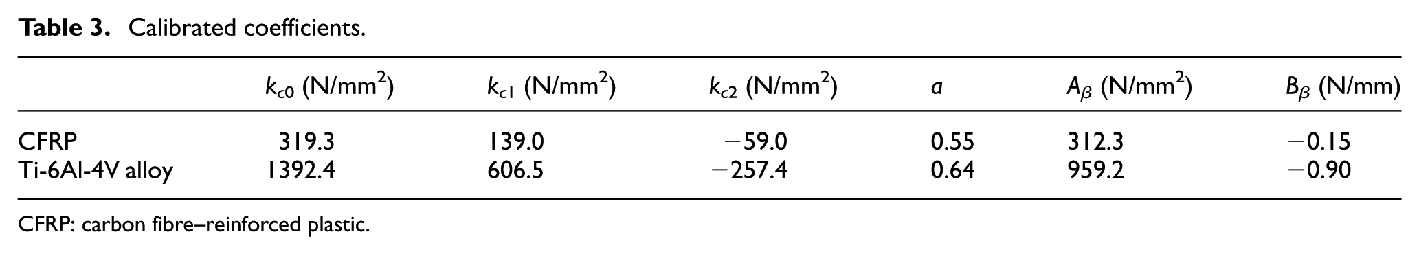
CFRP: carbon fibre–reinforced plastic.
Results and discussion
Model evaluation
The proposed model, whose coefficients are listed in Table 3, was used to predict the variation of the thrust force with machine time. The coefficient values were calibrated from experimental data. Lazar and Xirouchakis 37 proposed a model to predict the distribution of thrust force along the main cutting edges when drilling CFRP. In their model, a similar equation for the specific cutting pressure kc was presented and the coefficient kc2 was also negative. Pressure kc is positive along the drill edge because coefficient kc1 is positive and is much larger than coefficient kc2. The edge radius is never zero, even for a new tool. 30 Additionally, the predicted ploughing force is positive because Bβ is much smaller than Aβ. To validate the model, the predicted forces were compared with the measured forces. Table 4 lists the maximum thrust forces predicted by the present model and the experimental results. It is found that the proposed model performs well for Ti-6Al-4V alloy, with an average absolute error of 1.88%. The average absolute error for CFRP is 3.24%. The maximum absolute errors do not exceed 12.65% and 6.25% for CFRP and Ti-6Al-4V alloy, respectively. The absolute errors are within 5%, except for the first hole. A negative error indicates that the predicted thrust force is smaller than the experimental value.
Comparison of the maximum thrust forces.
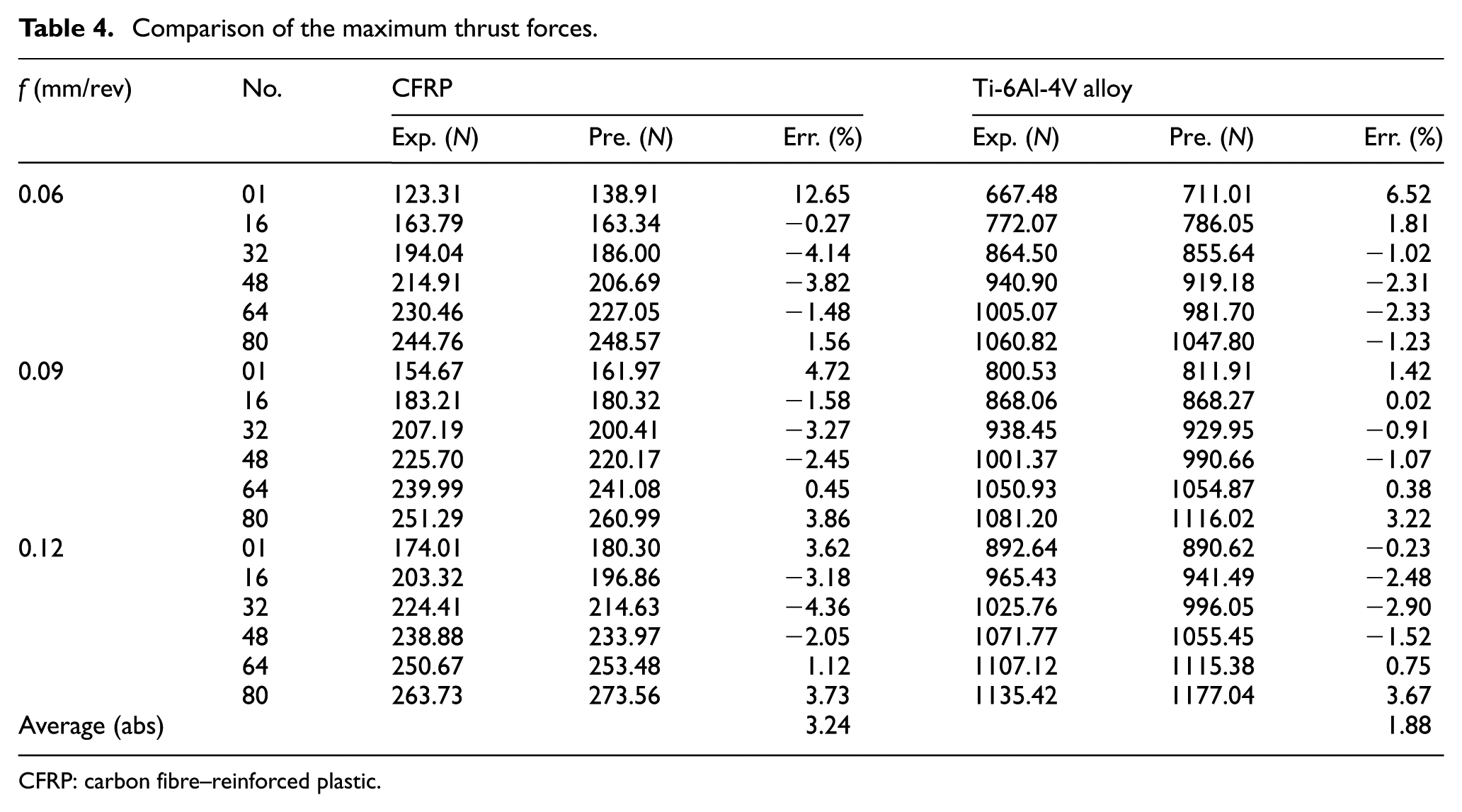
CFRP: carbon fibre–reinforced plastic.
The predicted errors for CFRP are slightly higher than those of titanium because of the high deviation of the thrust force in the CFRP region. A difference in the mechanism of material removal is the main reason behind the high discreteness of the recorded thrust force in the CFRP region. 14 For ductile materials such as titanium alloy, elastic–plastic deformation is the mechanism of material removal. Deformation is a steady state that leads to continuous formation of chips. In contrast, because of the brittleness of the fibre/matrix system, brittle fracture is the mechanism of material removal when drilling CFRP. Fractures are relatively unsteady and lead to powdery chips. Therefore, the deviation of the recorded thrust force in the CFRP region is larger.
Figure 12 shows the predicted and experimental thrust forces of the entire drill cycle with varying edge radii. As seen, the predicted and experimental force curves show the same trends and peak magnitudes for both materials. The predicted value is first higher and then lower than the measured value during the exit stage. The reason for this is that deformation of the workpiece at exit reduces the drop process of the thrust force and extends the machining time. This trend is obvious in high thrust force cases. Deformation occurs when uncut material is thin at the exit stage. The morphologies of the exit surfaces were observed during the exit stage when drilling CFRP, 40 which indicated the existence of deformation. The deformation causes exit burr for metals or protrusions for CFRP on the exit surface. Exit burrs are the main defect when drilling metals,5,6 whereas protrusions at the hole exit have been observed when drilling CFRP/Al stacks. 41
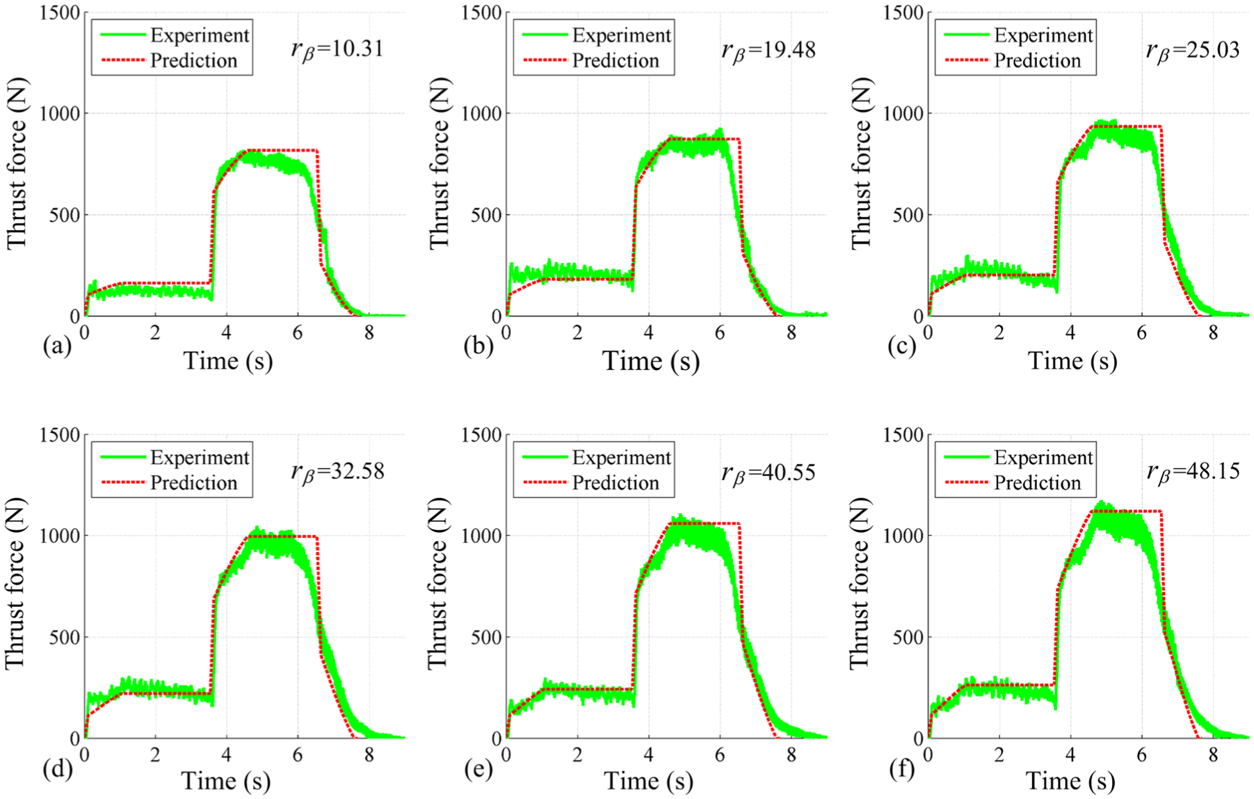
Comparisons of thrust forces (f = 0.09 mm/rev): (a) rβ=10.31μm, (b) rβ=19.48mm, (c) rβ=25.03μm, (d) rβ=32.58μm, (e) rβ=40.55μm, (f) rβ=48.15μm.
Effect of cutting parameters on edge radius
A round cutting edge is a suitable parameter to evaluate the bluntness of drill bits, as observed from Figure 9, indicating that the wear rate is identical on the rake and relief faces. A similar conclusion was reached in the work of Park et al., 32 where the edge wear and flank wear showed a similar amount of wear length at lower spindle speeds with carbide drills. Figure 13 shows the variation of the edge radius with the number of drilled holes and cutting distance at different feed rates. The edge radius increases with both cutting distance and the number of holes at varying feed rates. The growth rate of the edge radius increases with the feed rate when the same cutting distance is covered, whereas it slightly decreases with the feed rate when the same number of holes is drilled.
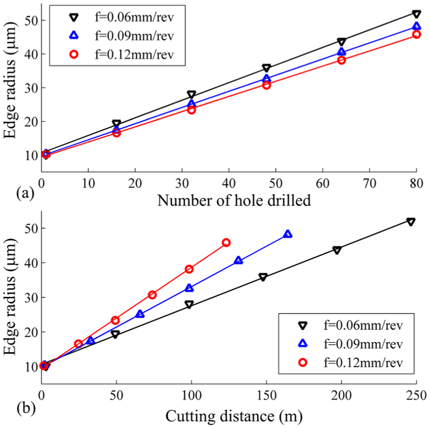
Edge radius versus the number of drilled holes and the cutting distance at varying feed rates edge radius versus (a) Number of drilled holes. (b) Cutting distance.
The edge radius is proportional to the square root of the product of the cutting force and cutting distance, according to equation (12). Both the cutting force and distance linearly increase with the number of holes drilled at a constant feed rate so that the product shows a quadratic increase. Furthermore, the edge radius has a linear relationship with the number of drilled holes. The cutting force increases as the feed rate increases, but the cutting distance decreases after a certain number of holes are drilled. According to equation (18), the ratio of the edge radius with varying feed rates after drilling the same number of holes can be expressed as equation (24)
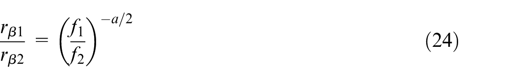
As shown in Table 3, coefficient a is positive. If f1/f2 < 1, then rβ1/rβ2 > 1, which suggests that the growth rate of the edge radius decreases as the feed rate increases. Similar relationships between tool wear and feed rate have been observed previously. In milling the composite, experimental results showed that flank wear of all of the investigated tools decreased as the feed rate increased at the same chip volume. 42 Tool wear showed an inverse relation to feed rate at the same cutting depth during the drilling process of metal-matrix composites. 43 Since exponent a/2 is small (approximately 0.3), the edge radius indicates no significant difference within the experimental range.
Effect of the edge radius on thrust force
As observed from Figure 10, the maximum thrust force increases with feed rate for both materials when the CFRP/Ti-6Al-4V stacks are drilled. This is somewhat analogous to what Ramulu et al. 17 reported in their work. In this study, tool wear is characterised by the cutting edge radius. With an increase in the edge radius, the thrust force essentially increases linearly, as observed from Figure 11(a) and (b). A similar correlation between thrust force and tool wear was also found in drilling composite materials.30,35 Two cutting elements with different edge radii are presented in Figure 14. The two elements have the same cutting depths tc, rake angles γ0, and relief angles. For the round edge, the rake angle varies from −π/2 at contact point P to γ0 at point S. Previously, an equivalent rake angle computed from the ratio tc/rβ was employed to calculate the cutting force of a round edge. 44 In this work, the equivalent rake angle (γe) of arc SP is used to explain the influence of the edge radius on the thrust force. The angle γe is smaller than γ0. The equivalent rake angle is identical for the cutting elements with the same rake and relief angles because the round part of the edge has the same shape.
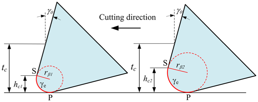
Cutting elements with different edge radii.
The unit cutting force acting on a round edge is larger than that on a sharp edge because the cutting force decreases as the rake angle increases. The thrust force of a round edge can be expressed as equation (25)

where Tu,γ0 and Tu,γe are the unit thrust forces per cutting depth for rake angles γ0 and γe, respectively. Equation (25) indicates that the thrust force increases linearly with the edge radius. The results of linear fitting the ploughing force show that the coefficient of determination (R2) is larger than 0.95 for both materials (Figure 11(c) and (d)), which suggests that the ploughing force increases linearly with the edge radius. A similar relationship was found by Wyen and Wegener. In that case, the influence of the edge radius on the ploughing force in the feed direction was linear when titanium alloys were machined. 38 The thrust force increases equally with ploughing force at the same feed rate.
The increase in the feed rate results in a higher thrust force and torque, larger surface roughness, worse roundness of the hole, smaller burr defects, and larger delamination when the CFRP/Ti-6Al-4V stack is drilled.14,17,27,41 Despite the occurrence of various types of defects, delamination induced in CFRP and burrs produced in titanium are consistently among the most serious types of defects.14,45 Burr height is proportional to the thrust force for the same feed rate, 27 and delamination increases with the thrust force when drilling CFRP. 25 In this regard, models have been established to relate the thrust force with delamination and burr size.5–7 Notably, the model presented in this article could assist in determining when to change tools to control machining defects within a suitable range.
Conclusion
This article outlines the novel mechanistic model of worn drill bits to predict the variation of thrust force when CFRP/Ti-6Al-4V stacks are drilled. The model was evaluated by performing appropriate drilling experiments. On the basis of the results, the following observations and conclusions can be drawn:
The edge radius increases with both cutting distance and the number of drilled holes at varying feed rates, which is proportional to the square root of the product of cutting force and cutting distance.
The edge radius growth rate increases with feed rate when the same cutting distance is covered, whereas it slightly decreases with feed rate when the same number of holes is drilled.
The maximum thrust force increases with feed rate, and it essentially increases linearly with the edge radius of worn drills when drilling CFRP/Ti-6Al-4V stacks.
The predicted thrust force curves are in very good agreement with experimental results, with average absolute errors of the maximum value for CFRP and Ti-6Al-4V alloy of 3.24% and 1.88%, respectively.
Footnotes
Appendix 1
Declaration of conflicting interests
The author(s) declared no potential conflicts of interest with respect to the research, authorship, and/or publication of this article.
Funding
The author(s) disclosed receipt of the following financial support for the research, authorship, and/or publication of this article: The work reported herein is sponsored by the National Natural Science Foundation of China (51275410, 51305352, and 51475379).