
Abstract
According to the increasing needs of rotary table and spindle to satisfy high-precision machining requirements, the accuracy of rotary table and spindle becomes an important issue due to the error averaging effect of hydrostatic thrust bearing. The objective of this study is to research a methodology to guide the precision design of hydrostatic thrust bearing in rotary table and spindle. A run-out error model based on error averaging effect is established using the Reynolds equation, pressure boundary conditions, flux continuity equations of pad and dynamic equations of shaft. The axial run-out error and angular error are calculated considering perpendicularity error and flatness error of the components. The simulation results show that the two perpendicularity errors between axis line and thrust bearing bushing surface have same direction, and the axial run-out error could reach to the maximum values. Also, the flatness error of thrust bearing bushing surface has a big influence on axial run-out error. Following the outcomes, the precision design of hydrostatic thrust bearing was conducted. The axial run-out errors of rotary table and spindle with hydrostatic thrust bearing were experimentally studied, and the results have good coherence to the simulation data. The run-out error model is demonstrated to be an effective approach to guide the precision design of hydrostatic thrust bearing in other rotary tables and spindles.
Keywords
Introduction
Hydrostatic thrust bearings are wildly used in rotary table and spindle in ultra-precision machine tools1–4 and high-precision manufacturing system 5 due to their high run-out accuracy which was induced by the error averaging effect of pressured oil or gas film. By comparison with rolling contact bearings, oil hydrostatic thrust bearings are given good damping and high stiffness properties 6 and minimum axial run-out error can be achieved. Aerostatic bearings are employed in high-speed spindles for bore grinding and precision milling, but with low stiffness.7–9 There are lots of research literature works published over the last two decades, both theoretically and experimentally, on the performance of oil or water hydrostatic thrust bearing or aerostatic bearing, mainly stiffness, damping characteristics, flow rate and load capacity.10–17 Also, the effect of structural parameters on the performance of hydrostatic thrust bearing18–22 was investigated by some researchers. However, the accuracy of hydrostatic thrust bearing is the most important factor, which determined some other properties. So, it is essential to thoroughly study the relationship between geometric errors and run-out error of hydrostatic thrust bearing.
For the run-out error in hydrostatic bearing, Kane et al. 23 designed an angled-surface self-compensating hydrostatic bearing and found error averaging ratio can reach 50 times. Hwang et al. 24 considered surface contour errors of axis and bearing, solving pentathlon errors of spindle by geometric relationships and force equilibrium equations. Yabe and Ishida 25 found out the axial run-out error in thrust bearing was mainly caused by the perpendicularity error between axis and bushing surface, which the error can be solved by dynamic equations of rotation shaft. Some other geometric parameters, like the angle between thrust surface of the housing and the rotation axis, and the angle between shaft’s bearing surface and rotation axis were considered to estimate the rotation accuracy of hydrostatic thrust bearing. 26 The hydrostatic thrust bearing run-out accuracy will decrease by the unparallel error of the bearing and the runner surface. 27 With the aim to analyze the geometric error, Stout and Barrans 5 stated that geometrical errors created in manufacture should be limited to 10% of the bearing clearance. Hydrostatic guideways are a sort of thrust bearing and the effect of guide rail geometric error on motion straightness was analyzed, also some suggestions for precision design were given.28,29
The above-mentioned works were conducted on the run-out error of hydrostatic thrust bearing by simulating calculation and experimental verification, but the internal quantitative relation between bearing parts geometric error and bearing rotation accuracy is not available, which means the precision design method should be further investigated. Because of the error averaging effect in hydrostatic bearing, the precision design method is different from traditional contact bearings. For this purpose, a run-out error model considering the Reynolds equation, pressure boundary conditions, flux continuity equations of pad and dynamic equations of shaft for hydrostatic thrust bearing was established. The run-out errors of hydrostatic thrust bearing in rotary table and spindle are calculated. The experimental results verified the correctness of the proposed precision design method.
Methodology
Error source analysis
The 3D models of hydrostatic thrust bearing in rotary table and spindle are shown in Figures 1 and 2, respectively. The schematic diagram is shown in Figure 3. The shaft, thrust bearing 1 and thrust bearing 2 were integrated together by screws, which constitute the rotational component of hydrostatic thrust bearing. The shaft manufacturing error contains flatness error of end faces 1 and 2 and the perpendicularity error between two end faces and axis line. The flatness error is the major manufacturing error of thrust bearings 1 and 2.
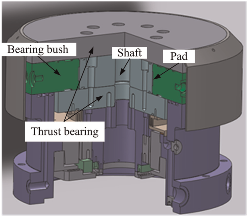
3D model of hydrostatic thrust bearing in rotary table.
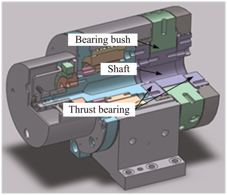
3D model of hydrostatic thrust bearing in spindle.
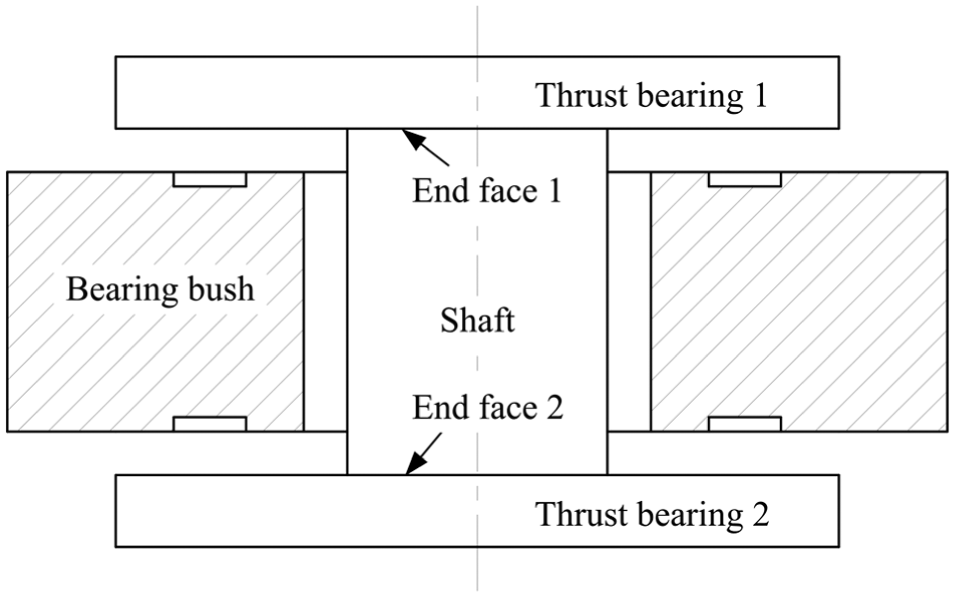
Hydrostatic thrust bearing schematic diagram.
Assuming that there were no deformations of assembled parts, the effect of flatness error of two end faces on oil film thickness can be neglected. So, the perpendicularity error between axis line and end face is one of main factors that affect oil film clearance in hydrostatic thrust bearing.
In practice, the flatness error of thrust bearing look similar to “saddle-shaped” is at all inevitable due to the manufacturing error of grinding machines. The oil film thickness changes with the rotation of shaft system. So, the flatness error of thrust bearing is another main factor which can affect the bearing clearance and hence run-out accuracy.
Run-out error modeling
The direct reason of axial run-out error is the variation of lubrication film clearance due to the form errors of thrust bearing or perpendicularity error between thrust bearing and rotation shaft. A model for calculating axial run-out error in hydrostatic thrust bearing was established, which consisted of four steps: (1) oil film clearance function, (2) the Reynolds equations of land, (3) flux continuity equations and (4) dynamic equations of shaft.
Oil film clearance function
In the first context, the perpendicularity errors cause the variation of oil film clearance. As shown in Figure 4, there exist perpendicularity errors between axis line and two end faces. The oil film clearance can be represented as
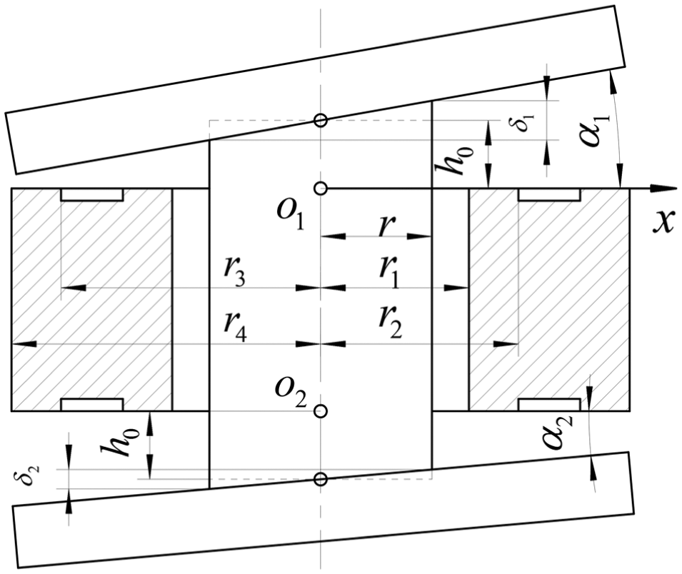
Perpendicularity errors in hydrostatic thrust bearing.
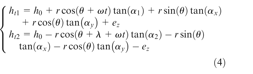
In addition, the angle phase difference between the two perpendicularity errors was described by introducing the sign λ. Consequently, the oil film clearance function can be expressed as
where ht1 and ht2 are oil film clearance of thrust bearings 1 and 2, respectively. The α1 and α2 are inclination angles, α1 > 0, α2 > 0 and the values are shown in equation (2)
where δ1 and δ2 are two perpendicularity errors (µm), δ1 > 0, δ2 > 0. The d is shaft diameter and d = 2r.
The second scenario is the variation of oil film clearance caused by “saddle-shaped” flatness error. In practice, the flatness error of thrust bearing look similar to “saddle-shaped” is at all inevitable due to the manufacturing error of grinding machines. The “saddle-shaped” flatness error of thrust bearing can be represented by quadratic function y = kx2, as shown in Figure 5. The oil film clearance can be represented as ht = h0+y in the cross section of shaft in the x direction.
“Saddle-shaped” flatness error in hydrostatic thrust bearing.
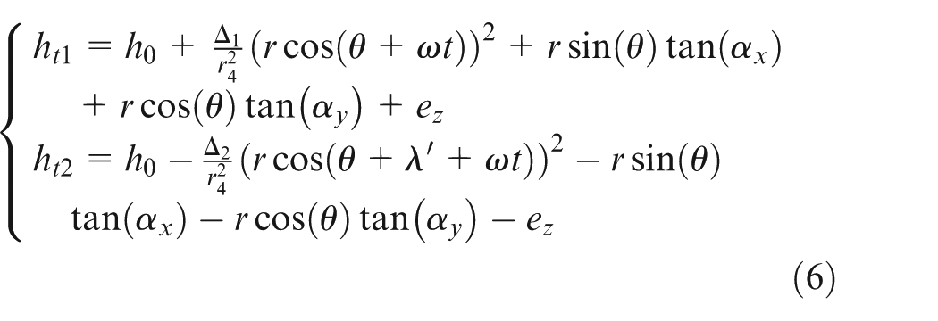
Similarly, the angle phase difference between the two flatness errors was described by introducing the sign λ′. And the oil film clearance function can be expressed as
where Δ1 and Δ2 are two flatness errors of thrust bearings 1 and 2, respectively. The Δ1 > 0 and Δ2 > 0. If the values are smaller than zero, the error direction is opposite to original conditions, as shown in Figure 5.
The oil film clearance function considering perpendicularity error can be represented as
For
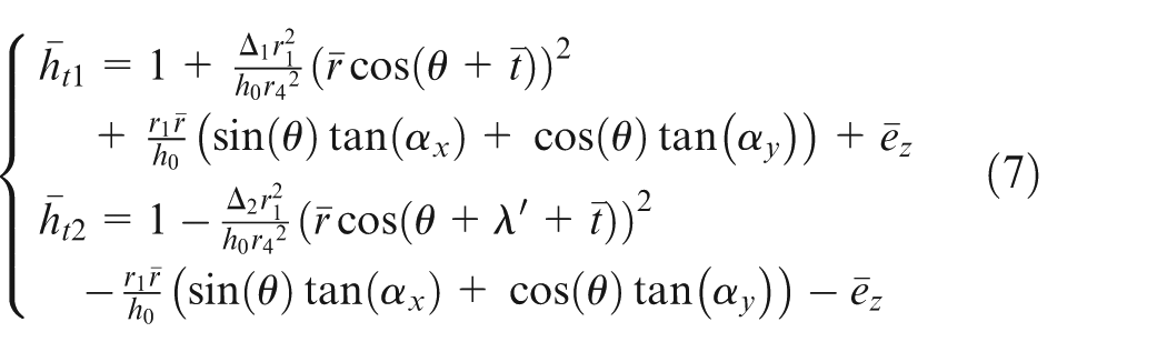
The oil film clearance function considering “saddle-shaped” flatness error can be represented as
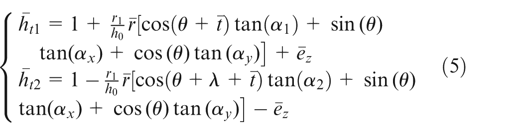
The corresponding dimensionless form of oil film clearance can be written as
The Reynolds equations of land
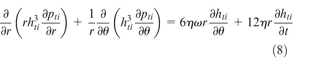
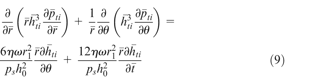
The pressure distribution of thrust bearing is pti (i = 1–2, representing the up and down thrust bearing, respectively). The pressure distribution on the land can be solved by the Reynolds equation, 30 as shown in equation (8)
Setting
The pressure boundary conditions of pad are given as
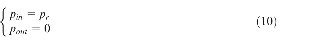
where pin and pout are pressure values of lubricating oil inflow and outflow the land, respectively. The pr is the lubricating oil pressure in the recess.
Flux continuity equations
For convenient calculation, convert the pad with scallop shape to rectangle style. The ijth pad schematic diagram is shown in Figure 6, the i represents the ith thrust bearing and the j represents the jth pad. The θl is the angle of land and θr is the angle of recess.
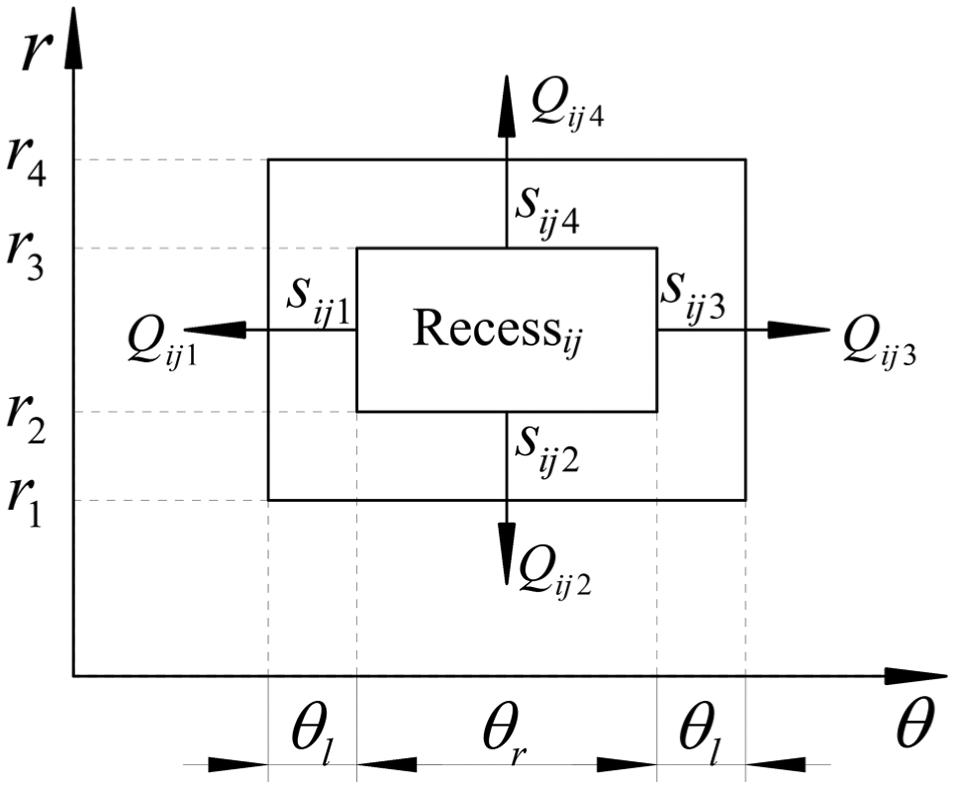
The pad schematic diagram in rectangular coordinates.
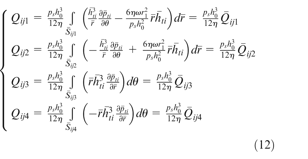
The flux squeezed out from the land of ijth pad is given as

where Qij1, Qij2, Qij3 and Qij4 are fluxes of the four lands, respectively. And the corresponding expressions are given as
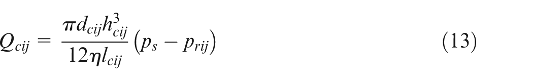
The flow of the ijth annular slot restrictor28,29,31 is expressed as
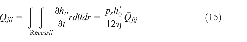
Regardless of the lubrication oil compressibility, the flow Qcij through the restrictor is equal to the sum of the flow Qoutij flows out the pad and Qjij squeezes out from the pad when shaft rotated. So, we can get the following two equations

So, the dimensionless form of flux continuity equation can be represented by

Dynamic equations of shaft
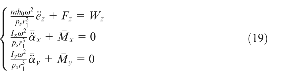
The dynamic equations of rotation shaft in hydrostatic thrust bearing can be expressed as
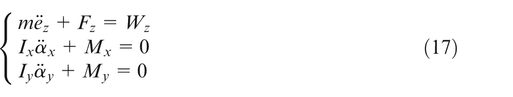
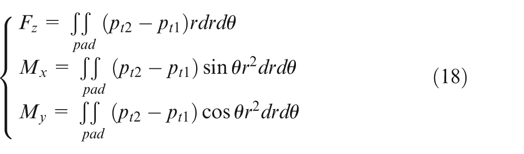
In equation (17), Wz is the external load on the rotation shaft in the z direction, Ix and Iy are moment of inertia about x and y axis, respectively. The expression of Fz, Mx and My is given as
The dimensionless form of rotation shaft dynamic equations can be written as
Solving the above equations, the axial run-out error and angular error caused by geometric error in hydrostatic thrust bearing can be derived.
Simulation results and precision design
Simulation results
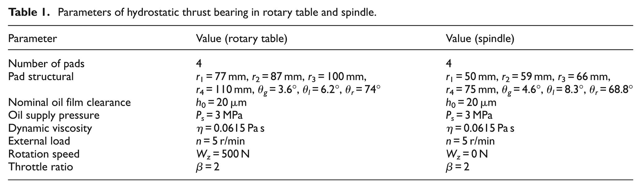
The research objects were two realistic hydrostatic thrust bearings in a rotary table and spindle. The COMSOL Multiphysics software was used for solving the model. The related parameters are shown in Table 1. The θg is the angle of the oil-returning slot.
Parameters of hydrostatic thrust bearing in rotary table and spindle.
Effect of perpendicularity error on axial run-out error
We assume that the perpendicularity error value is 5 µm, for both δ1 and δ2. The effect of phase difference between the two perpendicularity errors on axial run-out error and angular error is shown in Figure 7. It can be concluded that both the axial run-out error and the angular error value decrease with an increase in absolute value of λ. When the λ is equal to zero which also means the two perpendicularity errors have same direction, the axial run-out error and angular error reach the maximum value simultaneously. The axial run-out error and angular error reach the minimum value that approaches zero as the two perpendicularity errors have completely opposite direction.
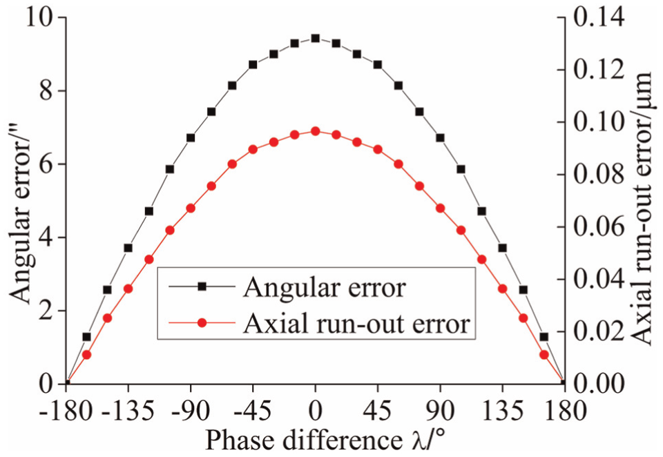
Relationship between λ and axial run-out error, and angular error.
Subsequently, the relationship between perpendicularity error value and run-out error was studied. The two perpendicularity errors have same direction when δ1 = δ2. Where δ1 = −δ2 means the two perpendicularity errors have opposite direction. The axial run-out error and angular error with different δ1 and δ2 in hydrostatic thrust bearing are shown in Figures 8 and 9, respectively.
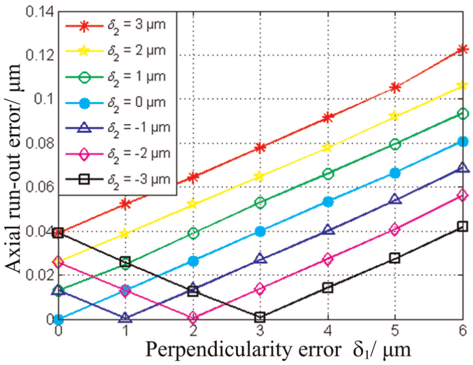
Relationship between perpendicularity error value and axial run-out error.
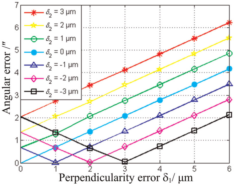
Relationship between perpendicularity error value and angular error.
As shown in Figures 8 and 9, the axial run-out error and angular error increase with the rise of δ1 when δ2 is equal to zero. As δ1 = −δ2, the axial run-out error and angular error are very small which is roughly equal to zero. This phenomenon was mainly attributed to closed structural form of hydrostatic thrust bearing, where the oil film reaction force variation of the double bearing bushing surface caused by the change of oil film clearance have the same value and with opposite direction, although great variability of oil film clearance was observed at different positions when the shaft system rotated. So, the axial run-out error and angular error have small values because a relatively equilibrium state has always maintained. And an important thing to note is in terms of what that physically means, as δ1 = δ2, the parallelism error of the two end faces is zero. In this situation, the axial run-out error and angular error increase with an increase in perpendicularity error. To sum up, the axial run-out error and angular error increase with an increase in absolute value of δ1 + δ2, whether the direction is same or opposite. This is because the greater the absolute value of δ1 + δ2, the greater the inclination angle of axis line will be. However, oil film reaction force variation will increase due to uneven oil film clearance when the shaft system has large pendulum angle, which leads to large axial run-out error.
In spite of high run-out accuracy being reached when the two perpendicularity errors have the same value in different directions, it could present a difficult challenge for assembling processes. In practice, the precision of perpendicularity should be guaranteed at a high level. And if not, the direction of perpendicularity error of end face 1 should be measured, evaluating the direction of error in machine tool. Then the end face 2 was machined to make sure it has an opposite direction with end face 1. Accordingly, the run-out accuracy in hydrostatic thrust bearing can be improved.
Effect of flatness error on run-out error
The axial run-out error with different “saddle-shaped” flatness errors Δ1 and Δ2 in hydrostatic thrust bearing is shown in Figure 10. The axial run-out error increases with the rise of Δ1 when Δ2 is equal to zero. As Δ1 ± Δ2 = 0, the axial run-out error is very small, which is roughly equal to zero. This is also because of the closed structural form in hydrostatic thrust bearing, the variation of oil film reaction forces caused by varied oil film clearance have the same value.
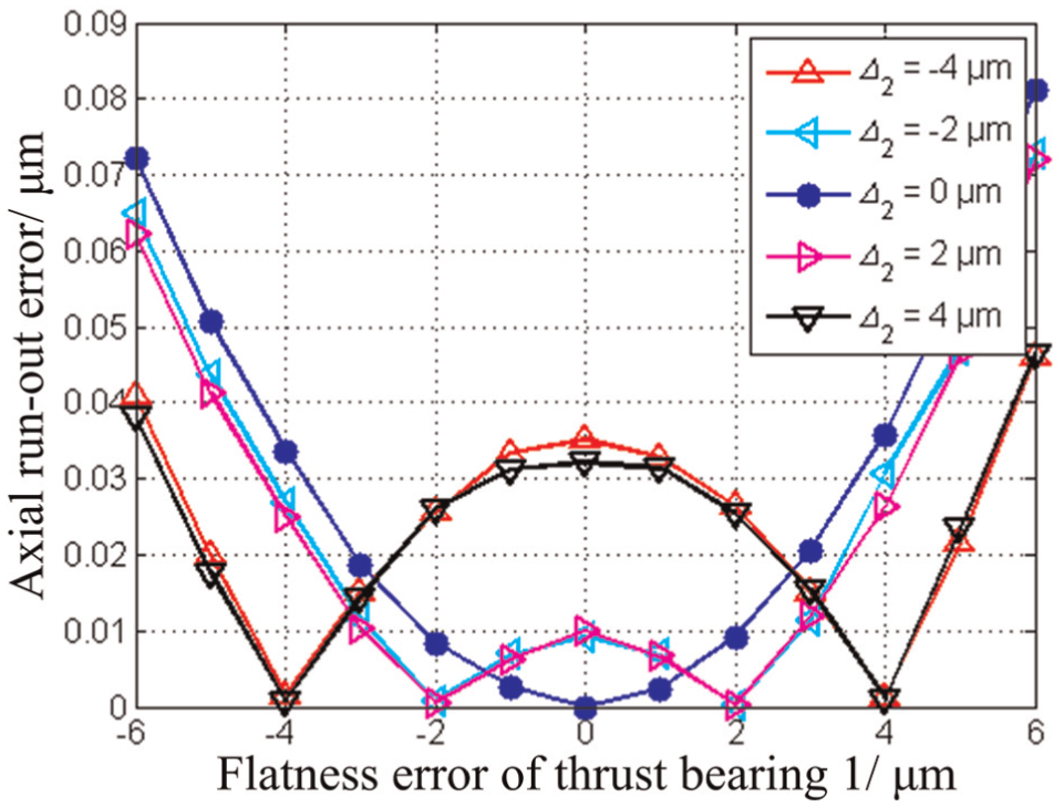
Relationship between two flatness errors and axial run-out error.
The effect of phase difference between the two “saddle-shaped” flatness errors on axial run-out error is shown in Figure 11. It can be found out that the axial run-out error reaches the maximum value when λ′ = 45°. The larger the sum of absolute value of Δ1 and Δ2, the larger will be the axial run-out error value.
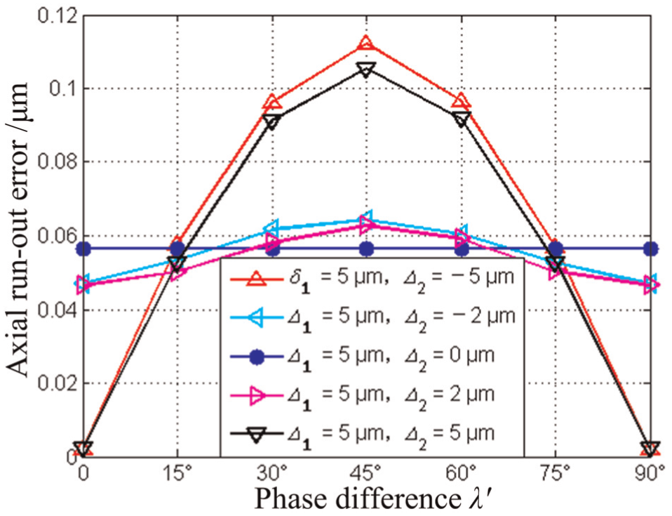
Relationship between λ′ and axial run-out error.
Precision design
According to accuracy indexes of hydrostatic rotary table, the axial run-out error is smaller than 0.2 µm. Considering the simulation results in Figures 8 and 10, and the produced errors during the assembly processes, for thrust bearing, perpendicularity error is 5 µm, thrust bearing flatness error is 5 µm.
Experimental verification
The measuring environmental conditions were as follows: room temperature was controlled within 21 ± 0.1 °C and the humidity was 45.4%. The measurement setup is shown in Figure 12. Tesatronic TT80 Inductance micrometer and high-precision inductive gauge head GT21 (repeatability 0.01 µm) were used to measure the two run-out errors. The standard sphere has a diameter 45 mm. For data acquisition, sample interval is 200 ms, 60 sampling points during every revolution and three revolutions were needed. Figures 13 and 14 are axial run-out error measurement results of rotary table and spindle, respectively. It is important to note that the eccentric value between the shaft axis and standard sphere axis was contained in the measured value. The run-out error = measured value − eccentric value.
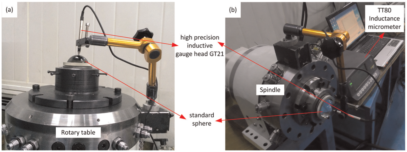
Axial run-out error measurement setup images: (a) rotary table and (b) spindle.
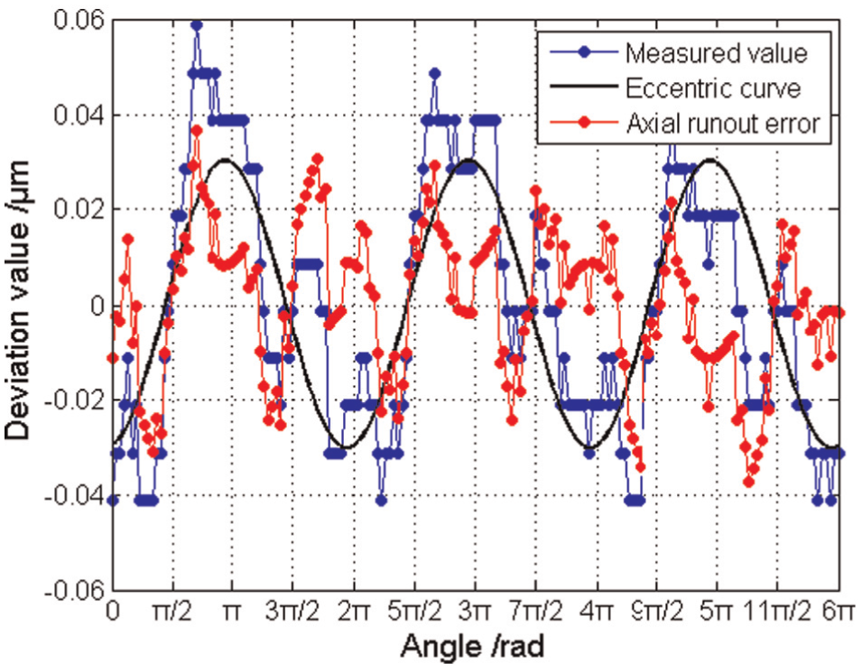
Measurement results of rotary table axial run-out error.
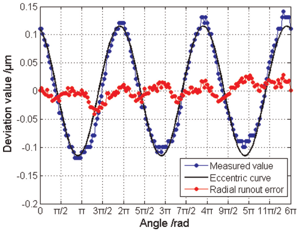
Measurement results of spindle axial run-out error.
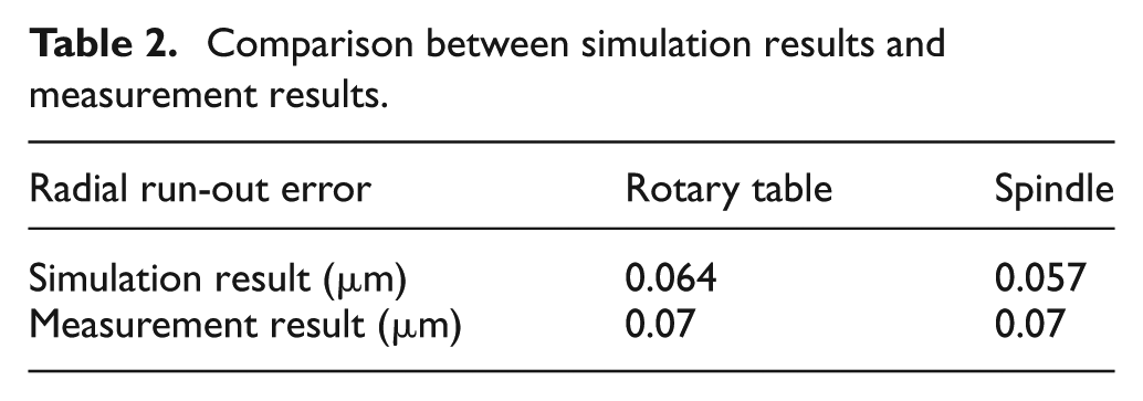
According to the value in the precision design, the calculated axial run-out errors are 0.064 and 0.057 µm for rotary table and spindle, respectively. Both the measured values are 0.07 µm. The comparison between simulation results and measurement results is shown in Table 2. It can be found that the experimental results are a slightly larger than numerical results. High precise measurement is a complicated process, it is difficult to get the accurate measuring data due to many influencing factors. Additionally, the elastic deformation of assembled parts could be happened under the actual working condition, which will change the pressured oil film clearance. Also, the difference may be induced by the assembly errors or oil film pressure variation in the pads. However, both the numerical and experimental results met the design requirement, and the deflection between these numbers are not significant.
Comparison between simulation results and measurement results.
Conclusion
A precision design method of hydrostatic thrust bearing in rotary table and spindle is presented in this study. From the simulation and experiment results, the following conclusions can be drawn:
The relationship between geometric error of hydrostatic thrust bearing and run-out error was analyzed quantitatively based on run-out error model considering oil film clearance function, the Reynolds equation, pressure boundary conditions, flux continuity equations of pad land and dynamic equations of shaft.
The axial run-out error and angular error increase with an increasing in perpendicularity error, and both reach the maximum value when the two perpendicularity errors have same direction and reach the minimum value that approaches zero as the two perpendicularity errors have completely opposite direction.
The axial run-out error increases with the rise of Δ1 when Δ2 is equal to zero. As Δ1 ± Δ2 = 0, the axial run-out error is very small which is roughly equal to zero. The axial run-out error reaches the maximum value when phase difference is λ′ = 45°.
The simulations based on the method can be used as a powerful tool for supporting the precision design of hydrostatic thrust bearing in rotary table and spindle. For hydrostatic thrust bearing, as the perpendicularity error is 5 µm and the thrust bearing flatness error is 5 µm, both the measured axial run-out errors of rotary table and spindle are 0.07 µm.
The experimental results validate that the proposed simulation approach is effective and efficient. The deflection between these numbers will be decreased as the fluid–solid interaction problem is considered in the model for further research.
Footnotes
Appendix 1
Declaration of conflicting interests
The author(s) declared no potential conflicts of interest with respect to the research, authorship and/or publication of this article.
Funding
The author(s) disclosed receipt of the following financial support for the research, authorship, and/or publication of this article: This work was supported by the National Natural Science Foundation of China (NSFC 51275395) and the National Science and Technology Major Project of the Ministry of Science and Technology of China (2012ZX04002-091).