
Abstract
The primary objective of this research is to investigate the effect of multi-wall carbon nanotubes on drilling of multi-wall carbon nanotube–embedded epoxy/glass fabric polymeric nanocomposites. The experiments were conducted on composites with varying the weight percentage of multi-wall carbon nanotubes content to analyse drilling-induced delamination and surface roughness, which affect the quality and property of the drilled holes. The drilling parameters considered are spindle speed, feed rate and drill diameter. The microstructure of the holes was characterized using field emission scanning electron microscopy methods. For correlating the effect of the weight percentage of carbon nanotubes with the referred drilling parameters, a mathematical model was used, based on response surface methodology. For development of the mathematical model, four factors, namely, spindle speed, feed rate, diameter of drill and weight percentage of carbon nanotubes, were taken into account. The result established that delamination and surface roughness are reduced as multi-wall carbon nanotubes’ content increases. Maximum improvement in delamination factor was observed in the case of 1.0 wt% multi-wall carbon nanotube–embedded epoxy/glass fabric polymeric nanocomposite, which is 25% and 31.09% at the entrance and exit sides of the hole, respectively. With an increase in the feed rate and the drill diameter, delamination factor increases; however, with an increase in spindle speed, delamination factor decreases. Lower value of surface roughness (1.113 µm) was observed in 1.5 wt% of multi-wall carbon nanotube–embedded epoxy/glass fabric polymeric nanocomposite. However, surface roughness increases with an increase in feed rate and drill diameter.
Keywords
Introduction
The use of glass fibre–reinforced polymer (GFRP) composite materials is steadily rising in various engineering fields due to their high strength and stiffness, good corrosive resistance as well as small thermal expansion. Machining of GFRP materials becomes necessary for getting net-shaped components. Researches have been largely focussed on addition of small content of nanofillers to the polymer matrix for increasing the mechanical and thermal properties of the GFRP composites. For enhancement of the mechanical properties of laminates, carbon nanotubes are considered to be potential fillers because of their excellent mechanical, electrical and thermal properties. Although to transfer the stress from matrix to fibres, carbon nanotubes act as interface.
Florian et al. 1 observed that strength, stiffness and fracture toughness of polymer composites are improved with the addition of carbon nanotubes. Machining of GFRP nanocomposite materials is different than other materials due to their anisotropic and non-homogeneous nature. Among several machining operations, drilling is the principal one for making holes in the assembled components in mechanical structures. It can affect the performance of the parts and life span of the GFRP nanocomposites. Serious problems that may occur during the drilling operation include debonding of fibres and matrix, thermal degradation, peel-up and pull-out of fibres. 2 Around 60% of the parts are rejected in aircraft industries only due to drilling-induced damages. Delamination of the composites reduces the strength of the material due to fatigue, pitiable assembly tolerance and affects the composite structure integrity. 3
Drilling tool geometry plays an important role in the drilling of the GFRP composite materials, particularly when the quality of the machined hole is a significant issue. 4 Ismail et al. 5 conducted a critical review on advances in twist drill design development for composite machining to minimize delamination during drilling and tool wear to obtain high-quality surface. Damage due to tool geometry is recognized as a serious problem during drilling. Murphy et al. 6 studied the performance of coated tungsten carbide drill during drilling of carbon fibre–reinforced polymer (CFRP) composite material. They found that using coated drill bit, the damage around the hole was minimum. Davim et al. 7 studied the behaviour of two distinct drills when drilling GFRP composite materials. Their objective was to establish a relation between the drilling parameters, with thrust force, delamination and surface roughness. Hocheng and Tsao 8 carried out an experiment with distinct drill. They concluded that the main factor responsible for delamination is thrust force. Rajamurugan et al. 9 used brad point drill for GFR–polyester composite materials having different diameters. They found that delamination factor increases when the drill diameter increases due to an increase in the contact area. This is responsible for an increase in the thrust force.
Drilling-induced delamination has two obvious mechanisms, namely, peel-up and push-out delamination at the entrance and the exit of drills. Peel-up delamination occurs when a drill bit touches the workpiece and fibres graze with flutes of the drill and peel upwards. Push-out delamination occurs at the exit side of the drill. By the time the drill reaches the exit side, the uncut thickness of the fibres gets reduced and due to the failure of the inter-laminar bonding, push-out delamination occurs. Wang et al. 10 studied about the mechanism of damage generation in the drilling of CFRP/titanium stack composite material. They found that the generation of high-temperature during drilling is the main reason for damage.
Mohan et al. 11 carried out an experiment on GFRP composite materials at different cutting speeds and feed rates. They recorded lower delamination at high cutting speed and low feed rate. Khashaba et al. 12 found that the cutting parameters also influence delamination at the entrance and exit sides of the drill. Singh and Bhatnagar 13 carried out an experiment on unidirectional GFR plastics and found that drill geometry affects delamination. When feed rates are high, delamination is maximum due to the impact of drill on the workpiece. 14 Arul et al. 15 established that the thrust force is related to the delamination factor. Accordingly, as the thrust force goes up, the delamination factor increases as well. Singh et al. 16 conducted an experiment for optimal control of thrust force for delamination-free drilling in GFRP laminates. They found that there is a critical limit on thrust force during drilling of FRP composite laminates below which no delamination occurs.
In the machining operations, surface finish is a significant factor. Roughness of the machined surface has been the focus of many studies. Surface finish is a significant design parameter and a determining factor in precision fit, fastener loads and fatigue loads. In addition to tolerance, proper selection of the cutting parameters is a significant prerequisite for control of surface roughness. 17 Feed rate and spindle speed also play an important role in determining surface roughness. When the feed rate is 0.10 mm/rev, surface roughness is high at a low cutting speed. However, surface roughness decreases when the cutting speed goes up. 18
Latha and Senthilkumar 19 investigated surface roughness in drilling of GFRP composites. They found that the feed rate and drill diameters have significant influence on surface roughness. When the feed rate increases, there is a significant rise in surface roughness, whereas a change in the diameter of drills results in slight changes in the surface roughness. For instance, with a 6-mm drill diameter, surface roughness value varies from 1.6502 to 3.5373 µm. According to Palanikumar et al., 20 surface roughness depends on the cutting parameters and drill diameter. It increases with an increase in the feed rate. Again, surface roughness is minimum when a small diameter drill is used. Spindle speed, on its part, has a modest influence on the drilling of GFRP. Takeyama and Lijima 21 found that when GFR plastics are used for machining operations, surface roughness is minimum at a high cutting speed. In this process, the cutting temperature becomes high which leads to softening of the work material.
During the last decade, a number of researchers have come to the conclusion that it is very important to minimize delamination during the machining process. Optimization and modelling methods have been used to find out the influence of the cutting parameters on delamination. Kilickap 22 carried out an experiment, based on L16 Taguchi’s experimental design, to determine the optimum cutting parameters. Li and Zhang 23 developed a cutting force model through orthogonal experiment method and analysis of variance (ANOVA). Their conclusion was that the depth of cut has significant influence on cutting force. Mishra et al. 24 used an artificial neural network for the prediction of drilling-induced damage in the drilling of unidirectional GFR plastic laminates. Their results indicate that the predictive model has been in good agreement with the test data.
Palanikumar et al. 25 developed an empirical model using ANOVA and Taguchi in the drilling of the GFRP composite materials. Zheng and Liu 26 carried out a wear test and developed a model for prediction of wear loss using the radial basis function and multilayer perceptron neural network model as well as the least mean square model. Li and Zhang 27 presented a model using orthogonal experiment method in the high-speed milling of polytetrafluroethylene (PTFE) composite to predict longevity of tools. Chen et al. 28 carried out an experiment on milling of Al 7075-T6 alloy. They developed a mathematical model using Taguchi and ANOVA to correlate all the factors crucial to surface roughness.
Palanikumar 29 developed a model to correlate the surface roughness and machining parameters in the drilling of GFRP composite and accordingly observed the effect of the cutting parameters on drilling. Sureshkumar et al. 30 developed a mathematical model for drilling into GFRP composites using full-factorial method and ANOVA. Their objective was to correlate the experiment results with general predictions. They found that the developed model was fit significantly with 95% level of confidence.
Many researchers used response surface methodology (RSM) for optimization and modelling. Sarma et al. 31 examined turning of GFRP composites and established a model for analysis of the cutting force using the RSM. Balaji et al. 32 carried out an experiment for optimization of the cutting parameters in the drilling of AISI 304 stainless steels using RSM. Krishnamoorthy et al. 33 carried out an experiment and presented an empirical model to study the delamination factor in the drilling of CFRP composite materials. They found the developed model to be compatible with the experimental results. Palanikumar and Davim 34 used RSM for predicting tool wear during the machining of the GFRP composites.
The objective of this study is to determine the influence of the drilling parameters such as spindle speed, feed rate, drill diameter and weight percentage of multi-wall carbon nanotubes (MWCNTs) on the delamination factor and the surface roughness of holes during the drilling of GFRP nanocomposites. RSM has been developed to correlate the drilling parameters and weight percentage of MWCNTs with different cutting parameters. ANOVA has been used to examine which factor has greater influence on drilling of GFRP nanocomposites.
RSM
The RSM is a statistical technique used mainly for modelling and analysis of experimental data. 35 It is an approach to explore the space for input factors. It helps to develop relationship between one or more responses and input parameters. First of all in RSM, the limit of experiment domain has to be defined. In this investigation, the weight percentages of MWCNT, drill diameter, feed rate and spindle speed are selected as the input parameters.
If the linear function is used for response modelling, then the function is first-order model as elaborated in equation (1)

where Y is a response function, the input variables are x1, x2,…, xk and
In this study, RSM is used to develop a model for output responses such as delamination factor (Fd) and surface roughness (Ra). Considering the weight percentage of MWCNT (w), drill diameter (d), feed rate (f) and spindle speed (v) as the input parameters as shown in equations (2) and (3)


The quadratic expression of RSM is used to see the influence of the parameters as described in equation (4)
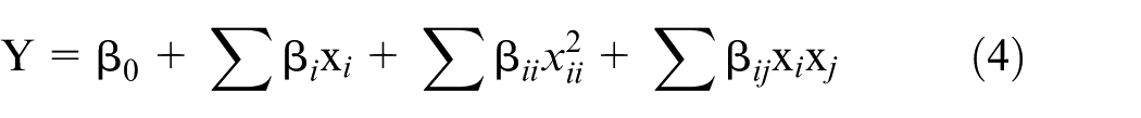
where β0 is the coefficient for the constant term, and the coefficients of linear, square and interaction terms are β i , β ii and β ij , respectively. For the analysis of the parameters, four factors and three levels of each factor are used. Box–Behnken design is used for better accuracy in the smallest possible number of the experiments. This is the most important design method used for establishing the relationship between the parameters and responses.
Experimental procedure and fabrication of materials
Materials’ fabrication and method
In this study, MWCNT-embedded epoxy/glass fabric nanocomposites were chosen as the test material. The materials were prepared using 12 layers of plain woven glass fibre of stacking order [45/−45], [45/−45], [30/−60], [30/−60], [30/−60], [0/90] // [0/90], [30/−60], [30/−60], [30/−60] [45/−45], [45/−45]. For preparation of nanocomposites, a calculated amount of MWCNTs, that is, 0.5, 1.0 and 1.5 wt%, was used in matrix to enhance the mechanical properties of laminates. MWCNTs with acetone were sonicated for 1 h at 20 kHz using ultrasonic vibrator to minimize agglomeration. Then the mixture of acetone and MWCNT was added to epoxy resin (Lapox L-12 ARL-12 Epoxy Resin; Atul Ltd, India) and again sonicated for another 60 min. To remove the acetone, the mixture was stirred at 80 °C for 60 min using a magnetic stirrer. After allowing the MWCNT–epoxy mixture to cool down to room temperature, so as to avoid premature curing, a low viscous curing agent (Lapox K-6 AH-312 Epoxy Hardener, Atul Ltd) was added and mixed using a mechanical stirrer rotated at 900 r/min for 5 min. Finally, the mixture was applied on glass fibre sheet by hand layup technique. The vacuum bagging method was used to apply pressure for squeezing out extra resin at room temperature.
Experiment procedure
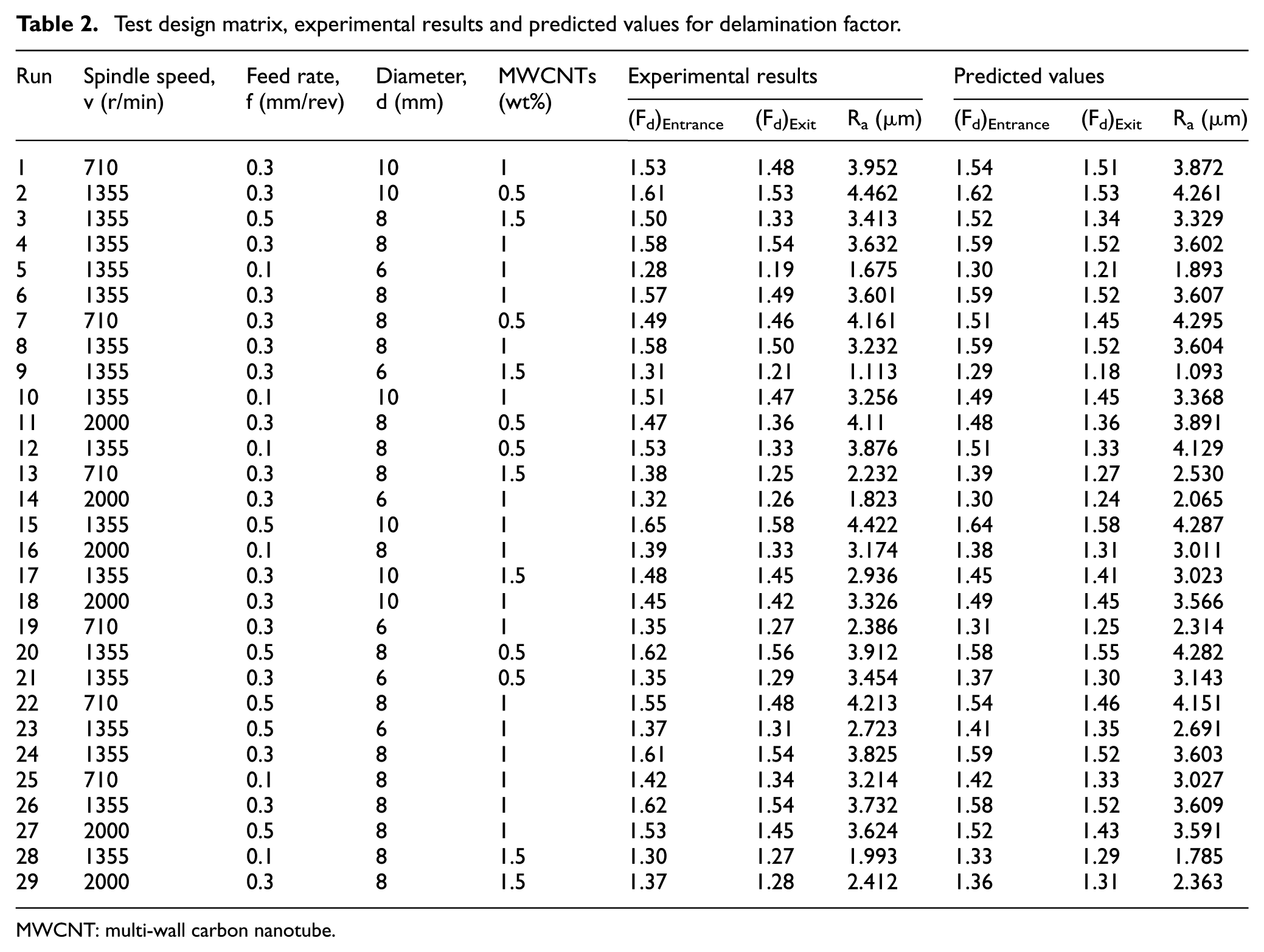
The GFRP nanocomposites, having size of 100 × 100 × 5.40 mm3, were used in the experiment. The basic purpose of the experiment was to find out the effect of the drilling parameters and weight percentage of MWCNT on delamination and surface roughness. The experiment was conducted on Batliboi BVR5 radial drilling machine with 8 kW of spindle power. Four parameters in the drilling process, namely, percentage of carbon nanotubes (in three levels), drill diameter (in three levels), spindle speed (in three levels) and feed rate (in three levels), were considered to be variables. Table 1 shows the parameters and their levels used in this study. A series of experiments were conducted according to the Box–Behnken design, as presented in Table 2, which gives the levels of variables used in design matrix. Table 2 also presents the experimental results and predicted values of delamination factor (at entrance and exit) and surface roughness. It consists of 29 experiments for development of a mathematical model on delamination and surface roughness of the holes. Different TiAlN-coated solid carbide drills were used for each specimen (i.e. 0.5, 1.0 and 1.5 wt% MWCNT-embedded epoxy/glass fabric polymeric nanocomposite) as a cutting tool as shown in Figure 1. However, due to the coating on drill bits, tool wear is negligible, therefore very less chance to affect the quality of hole during drilling.
Drilling parameters, weight percentage of MWCNTs and levels.
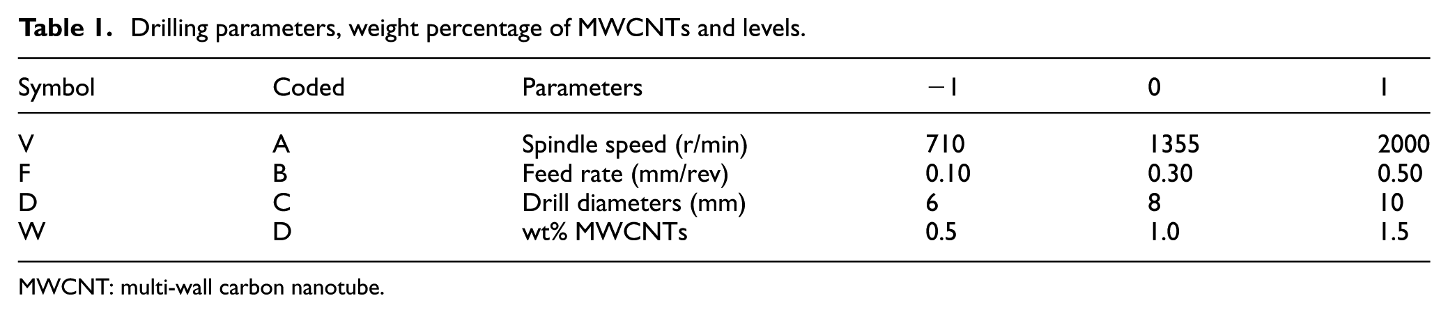
MWCNT: multi-wall carbon nanotube.
Test design matrix, experimental results and predicted values for delamination factor.
MWCNT: multi-wall carbon nanotube.
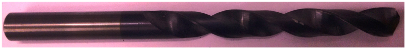
TiAlN-coated solid carbide drill.
The damages around the holes at the entrance and exit sides were assessed by a non-destructive test, that is, image processing technique. The holes were scanned at 1200 dpi; scanned images were taken for assessing damages around the hole using ImageJ 1.50 public domain software. With proper selection of brightness, binary and threshold, the maximum damaged zone diameter is measured for each hole as shown in Figure 2, where Figure 2(a) denotes the scanned image of hole, Figure 2(b) presents the initial processed image and Figure 2(c) indicates the final processed image in which the dark areas indicate the drilling-induced damage. The design of experiment was used for regression and graphical presentation of the obtained data.
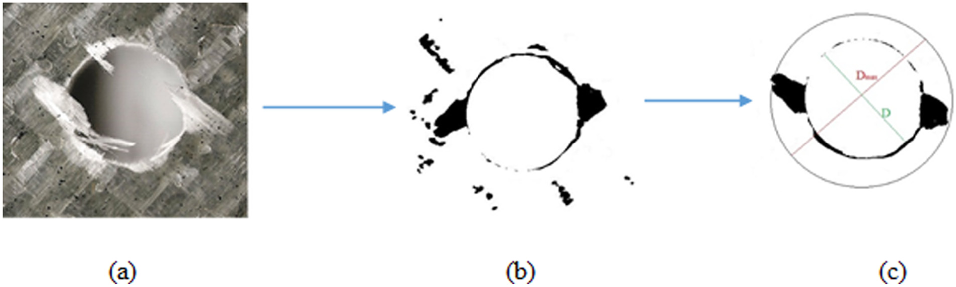
Digital image processing: (a) digital image, (b) initial processing and (c) final image.
Delamination and calculation of delamination factor
Delamination is a major cause of damage during drilling of GFRP nanocomposites. The damage at the entrance and the exit sides of the hole was assessed. It was measured by the ratio of the maximum damaged zone diameter (Dmax) to the hole diameter (D), as expressed in equation (5) 36
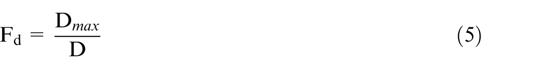
where the maximum diameter of the damaged zone is Dmax and diameter of the hole is D (mm), as shown in Figure 2(c).
Measurement of surface roughness
The surface roughness of the drilled hole was measured by Surftest SJ-210 manufactured by Mitutoyo America Corp. with 0.8 cut-off length and a moving speed of 0.5 mm/s according to the ISO 1997 standard. For each hole, four measurements were taken at different sections of the hole. The average of these values is listed in Table 2. The surface roughness measurement set-up and the surface roughness profile of the hole as observed in the drilling of GFRP nanocomposites are presented in Figure 3.
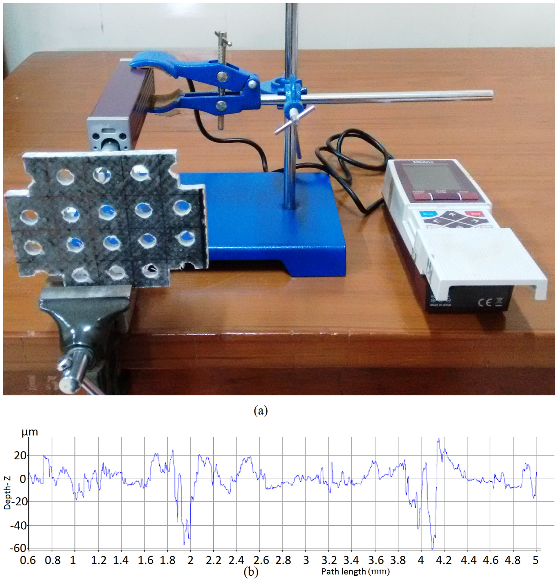
Process of surface roughness measurement: (a) measurement set-up and (b) surface roughness profile.
Results and discussion
Modelling of the drilling parameter using RSM
An empirical mathematical model was developed using RSM regression analysis. This model is used to predict the delamination factor at the entrance and exit sides of the hole. The summary statistics of the model for delamination factors are presented in Tables 3 and 4 while that of the surface roughness are denoted in Table 5.
Model summary statistics for the delamination factor at entrance.
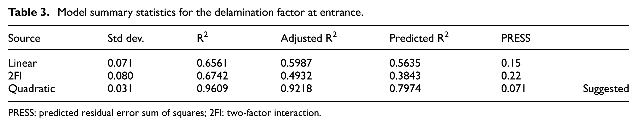
PRESS: predicted residual error sum of squares; 2FI: two-factor interaction.
Model summary statistics for the delamination factor at exit.
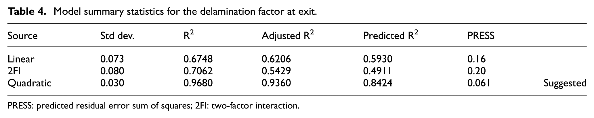
PRESS: predicted residual error sum of squares; 2FI: two-factor interaction.
Model summary statistics for the surface roughness (Ra).
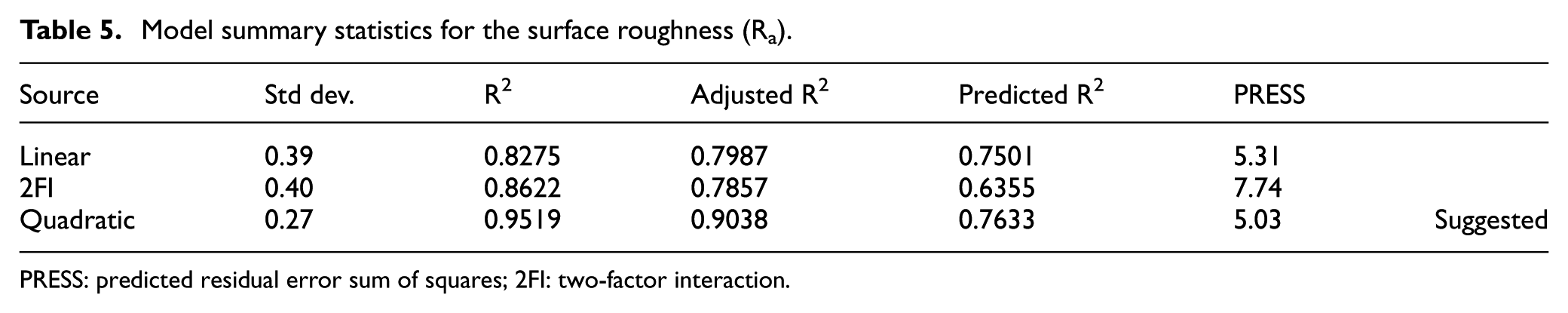
PRESS: predicted residual error sum of squares; 2FI: two-factor interaction.
From Tables 3–5, it can be seen that the obtained results of model summary statistics are consistent with Kilickap, 3 in which quadratic model is the best suggested model for delamination factor and surface roughness in the drilling of GFRP nanocomposites. The suggested model is formulated in equation (6)
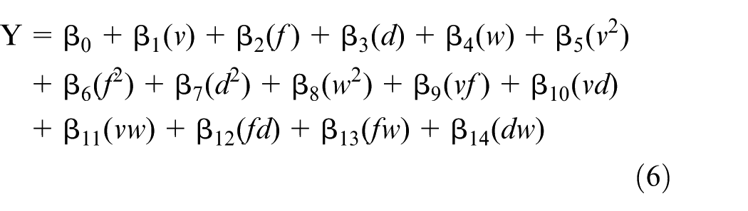
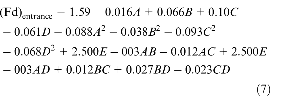
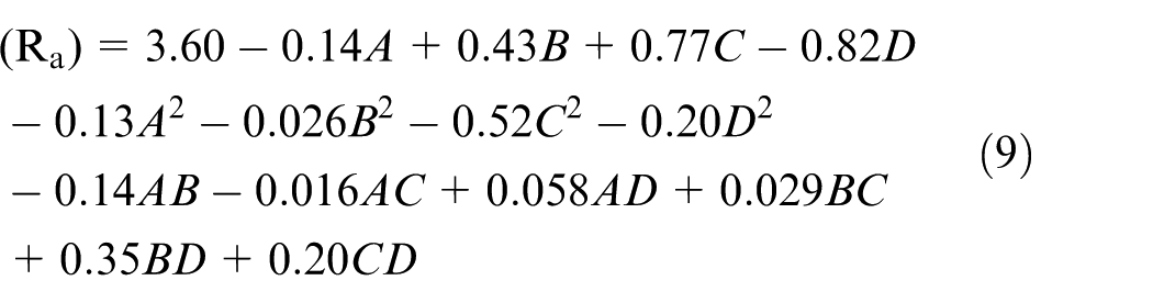
The values of coefficient were determined using regression. The developed mathematical model for the delamination factor (at the entrance and exit) and surface roughness are presented in equations (7)–(9) on the basis of the considered parameters’ level and their regression analysis using RSM. The equations for delamination factor and surface roughness are expressed below through coded value
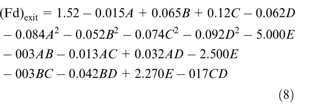
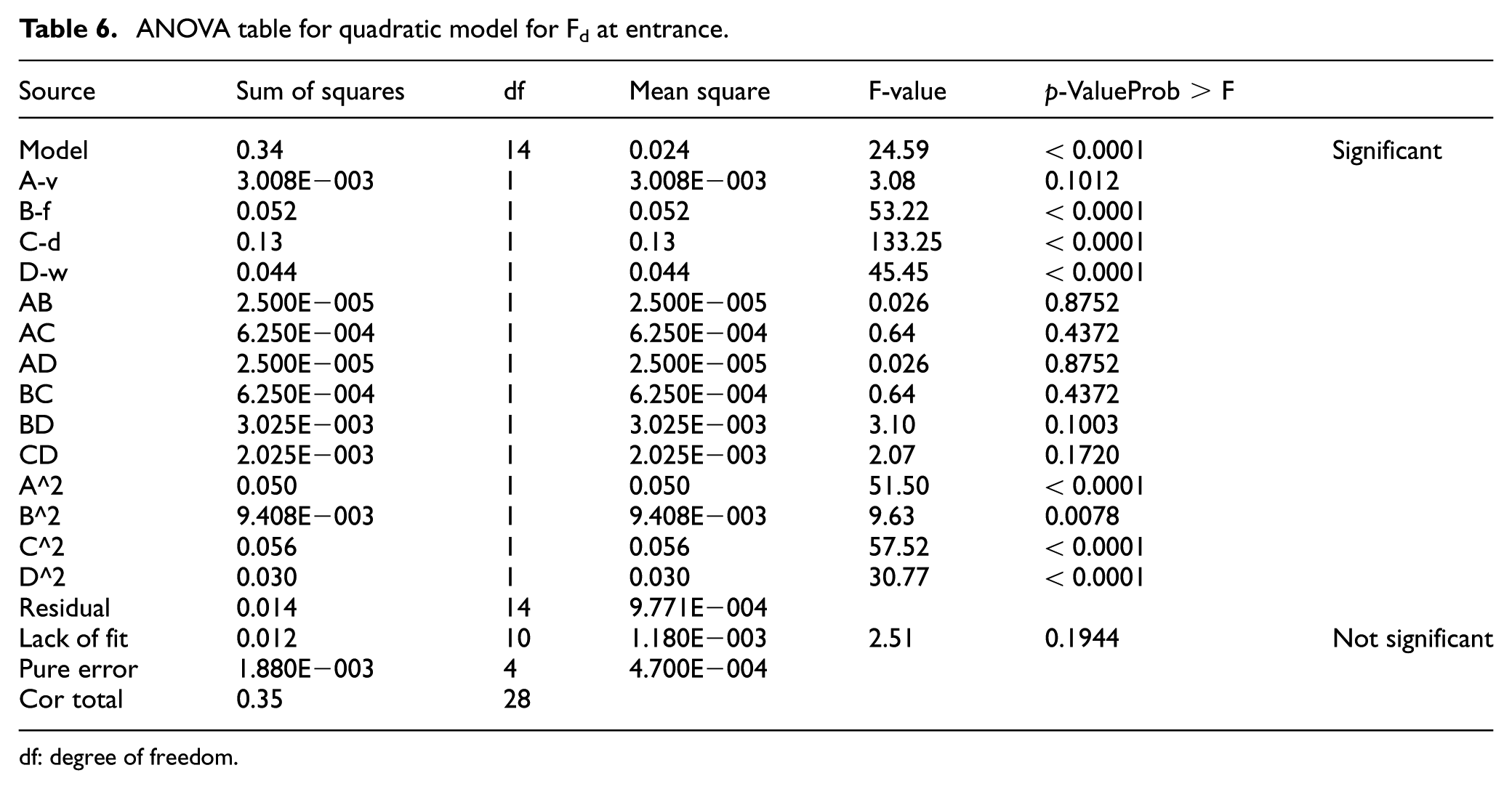
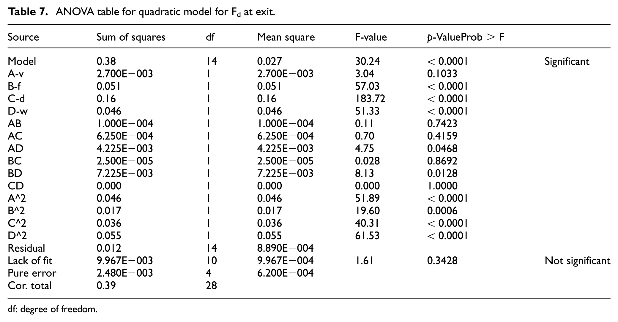
Both the experimental results and predicted values of delamination factor as well as surface roughness are presented in Table 2. To check the suitability of the model, ANOVA is used. The ANOVA result of delamination factor at the entrance is presented in Table 6. According to Table 6, the ‘F’ values of the processing parameters, obtained from the experiment data for delamination factor (at the entrance), are 133.25, 53.22, 45.45 and 3.08 for drill diameter, feed rate, weight percentage of MWCNT and spindle speed, respectively. Drill diameter is the most significant parameter followed by feed rate and weight percentage of MWCNT; however, spindle speed is less significant at 95% level of confidence. Table 7 presents the ANOVA result of delamination factor at the exit. From Table 7, it can be seen that the F value of the cutting parameters obtained from the experimental results are 183.72, 57.03, 51.33 and 3.04 for drill diameter, feed rate, weight percentage of MWCNT and spindle speed, respectively. For delamination factor at the exit, drill diameter is the most significant parameter because as the drill diameter increases, the contact area of the tool and the workpiece interface widens causing more damage around the holes; however, spindle speed is less significant.
ANOVA table for quadratic model for Fd at entrance.
df: degree of freedom.
ANOVA table for quadratic model for Fd at exit.
df: degree of freedom.
The signal-to-noise (S/N) ratio measures the precision of the model. A ratio greater than 4 indicates accuracy of the model. The obtained S/N ratio is 15.791 and 18.537 for the delamination factor at the entrance and exit sides, respectively. It indicates that the developed model is appropriate at 95% level of confidence within the limits of factors considered. The ANOVA results for surface roughness are presented in Table 8. It can be seen that the weight percentage of MWCNTs has the greatest influence on surface roughness followed by drill diameter and feed rate. However, spindle speed has very little influence on surface roughness. The F-values of the weight percentage of MWCNTs, drill diameter and feed rate are 111.39, 96.24 and 29.93, respectively. For surface roughness model, the S/N ratio is 16.475, which is greater than 4, indicating that the model is suitable within the acceptable level of confidence.
ANOVA table for quadratic model for surface roughness (Ra).
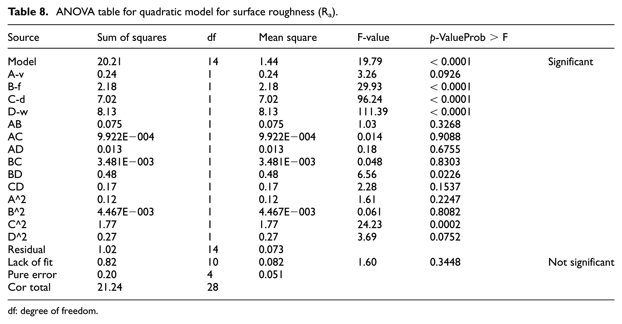
df: degree of freedom.
From Figure 4, it can be seen that the experimental results and the predicted results concerning the model are in good agreement. The normal probability plots of residual versus predicted results for delamination factors and surface roughness are shown in Figure 5, which is based on central limit theorem. 37 If all the residuals remain along the central line, it will indicate that the values are distributed normally. From Figure 4, it can be observed that all the values are spread along the central line, confirming that the proposed model is appropriate at 95% level of confidence.
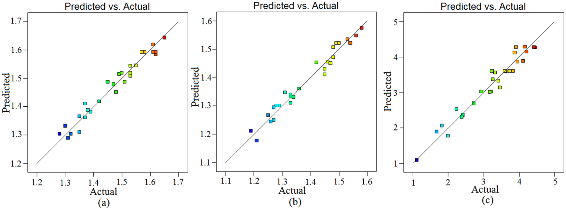
Experimental versus predicted results of delamination factor: (a) at entrance, (b) at exit and (c) surface roughness.
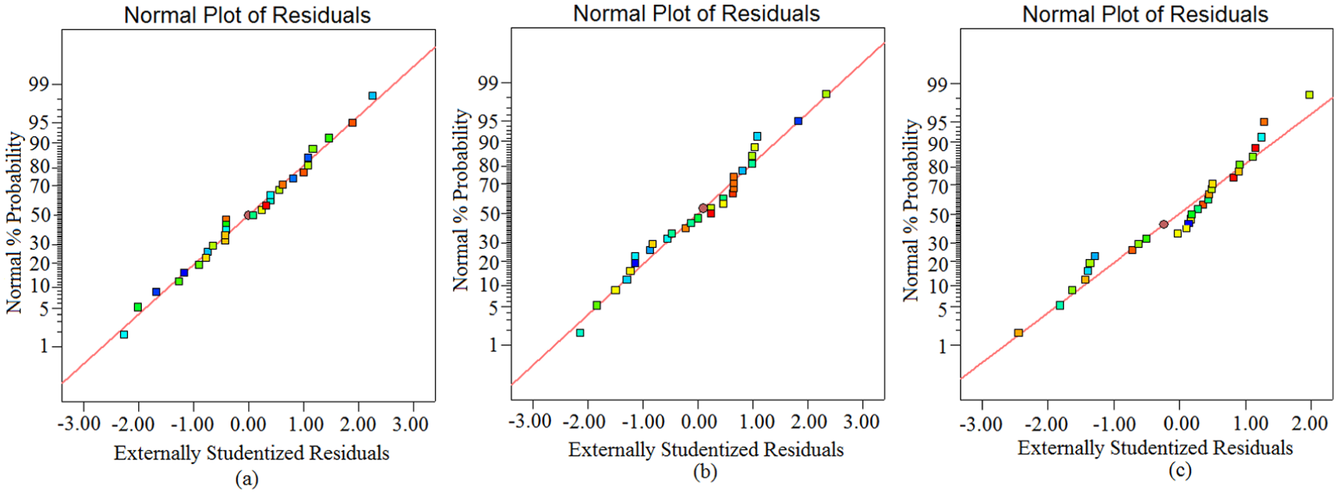
Residuals versus predicted response for delamination factor: (a) at entrance, (b) at exit and (c) surface roughness.
Validation of models
With a new set of parameters, an experiment was conducted to validate the obtained models. Multiple response values were measured and compared with the predicted values obtained from models. Table 9 presents the levels of variable used for validation of the obtained models. It also presents the experimental results and predicted values of output responses, that is, delamination factor (at entry and exit sides) and surface roughness of the hole in the drilling GFRP nanocomposites. Two trials were performed on each set of parameters and their percentage error of validation data is presented in Figure 6. From Figure 6, it has been noted that the percentage error between the experimental and predicted results is minimum which depicts the accuracy of the models.
Validation data for experimental and predicted results.
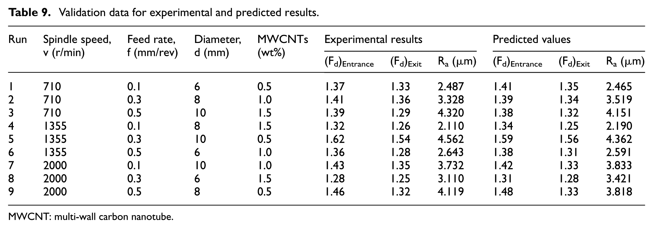
MWCNT: multi-wall carbon nanotube.
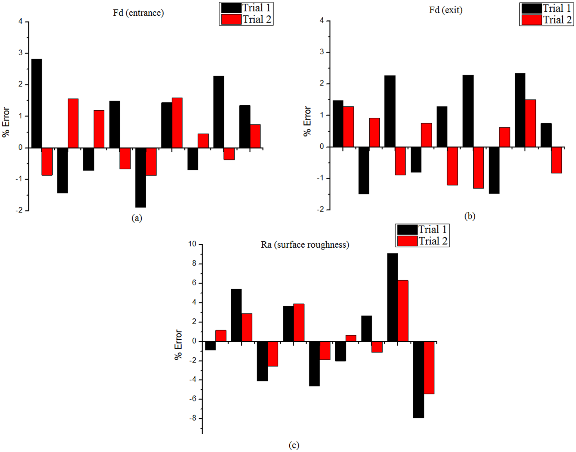
% Error between experimental and predicted results of (a) delamination factor at entrance side, (b) delamination factor at exit side and (c) surface roughness of hole.
Delamination analysis
Drilling of FRP composite materials is different from other materials due to their anisotropic behaviour. Nowadays, drilling of such type of materials is much more needed for industries. Drilling of GFRP composite materials may cause serious damages such as incomplete removal of fibres, delamination, fuzzing and protrusion of fibres. Although development of cracks between the plies due to delamination can ruin the mechanical performance of GFRP composite materials. To overcome these problems, MWCNTs are added to epoxy resin which improves the strength of the interface as well as the machinability of GFRP composite materials. There are two obvious mechanisms of delamination in the drilling of GFRP composite materials, that is, peel-up and push-out. The cutting edge of the drill grazes the laminates when the drill bit touches the workpiece. The grazed material peels off along the flutes of the drill; as a result, the upper lamina peels off causing peel-up delamination.
The delamination mechanism at the exit side works as the uncut plies bend elastically due to the compressive force exerted by the drill. When the drill approaches the exit side, resistance to the bending decreases due to the reduction in the pressure on the uncut plies. Next, as the bending stress increases, the inter-laminar strength of plies weakens. As a result, cracks develop around the hole when the drill point pushes down further. Then flexural rigidity of plies becomes weaker and it causes cracks to propagate easily. Due to this phenomenon, failings of inter-laminar bonding cause push-out delamination. However, with the addition of MWCNTs in epoxy resin, the strength of the materials and sticking capability of fibres as well as matrix increase. It also improves the machinability of the material because MWCNTs provide lubrication at the tool chip interface. However, to ensure damage-free holes, proper selections of the cutting parameters are essential.
Figure 7(a)–(f) shows the micrograph of the holes observed through scanning electron microscope (SEM) during the drilling of MWCNT-embedded epoxy/glass fabric polymeric nanocomposites. The micrographs were taken at the cut section of the hole wall. The field emission scanning electron microscopy (FESEM) images in Figure 7(a)–(d) show cut sections of the holes plagued with shear failure, fractured fibres and debonding as a result of weak bonding between the matrix and fibres. It has been observed that the cross section of the fibre glass of 0.5 and 1.0 wt% MWCNTs is not smooth, which indicates that the failure occurs largely due to debonding. Under the same machining condition, the cross section of the fibres for the 1.5 wt% doped MWCNTs shows smooth surface and strong bonding between fibers and matrix as shown in figure 7 (e)-(f). It can be noted that the failure depicts wrinkled patterns followed by smooth cleaved surface, which concludes that shearing is the prevailing failure mode in 1.5 wt% MWCNT-embedded fibres.
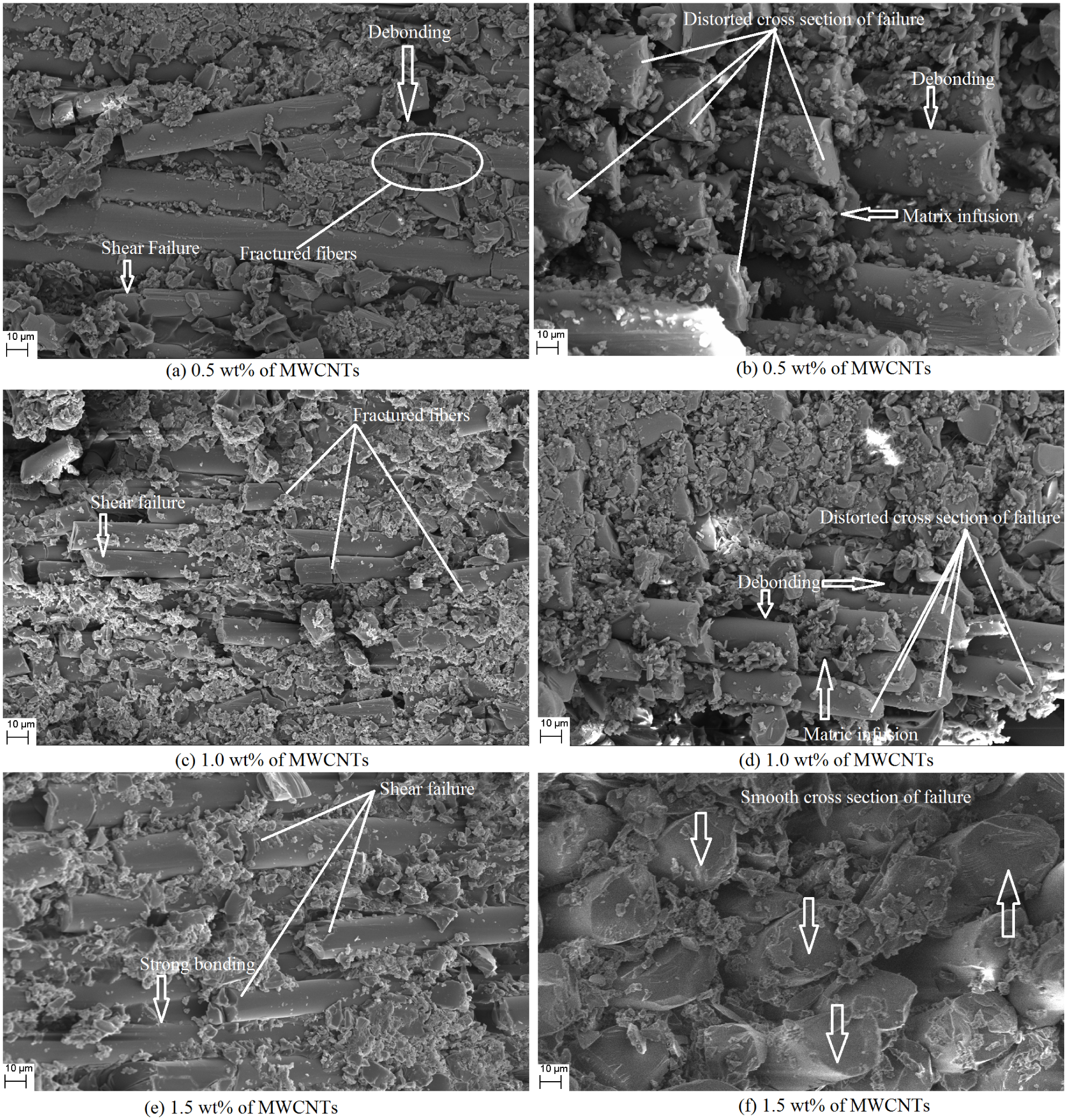
SEM micrograph of MWCNT–embedded GFRP nanocomposite.
Effect of drilling parameters and weight percentage of MWCNTs on delamination
During the drilling of MWCNT-embedded epoxy/glass fabric nanocomposites, damages around the holes occur due to thrust force induced on the workpiece when the drill bit touches the material, which happens due to the inhomogeneity in GFRP. This drilling-induced damage causes rejection of the part. Hence, optimization of the input process parameters is needed so as to obtain suitable results. The objective of this investigation is to examine the impact of the drilling parameters and weight percentage of MWCNTs on the delamination factor.
From several optimization techniques, RSM is found to be the most suitable technique to analyse the experimental results. It consists of several independent factors influencing a dependent response. Figures 8–13 present three-dimensional response plot of delamination factor against spindle speed, feed rate, drill diameter and weight percentage of MWCNTs.
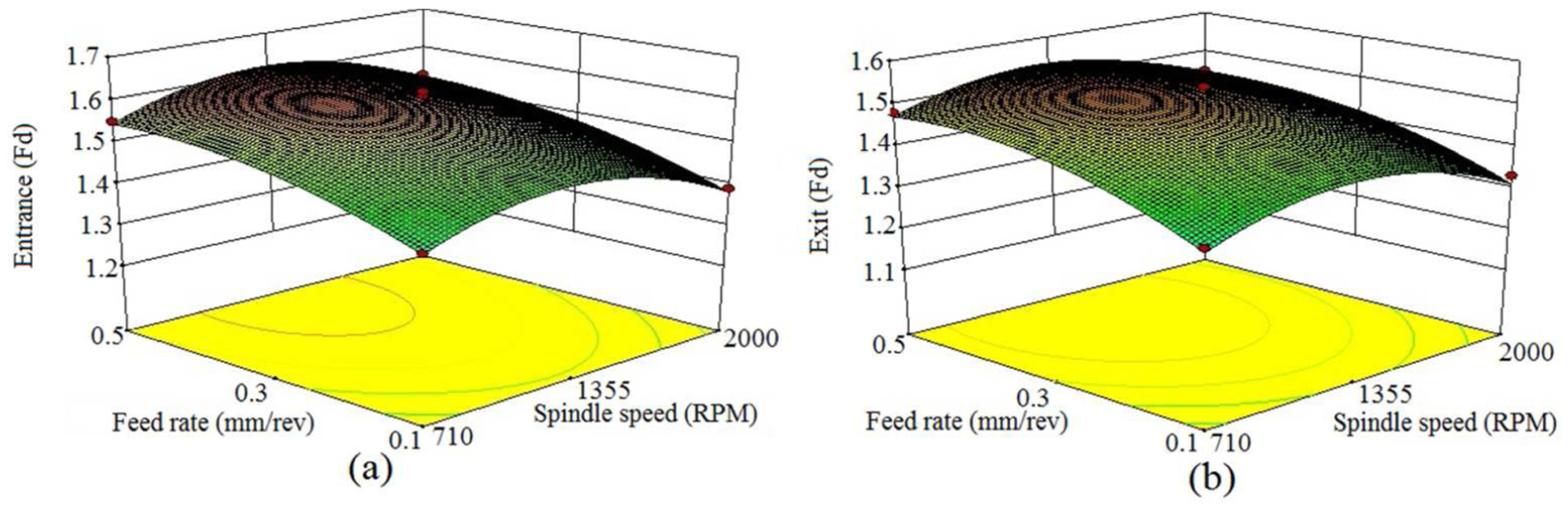
Delamination factor response graph as a function of feed rate and spindle speed: (a) at entrance and (b) at exit.
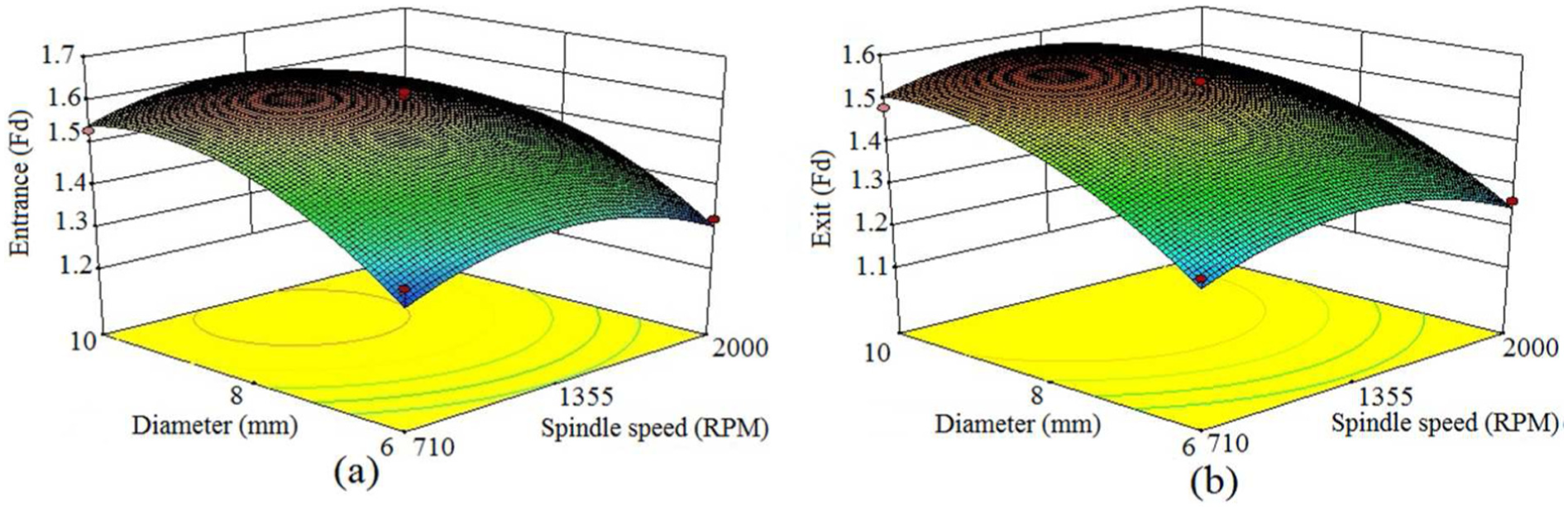
Delamination factor response graph as a function of drill diameter and spindle speed: (a) at entrance and (b) at exit.
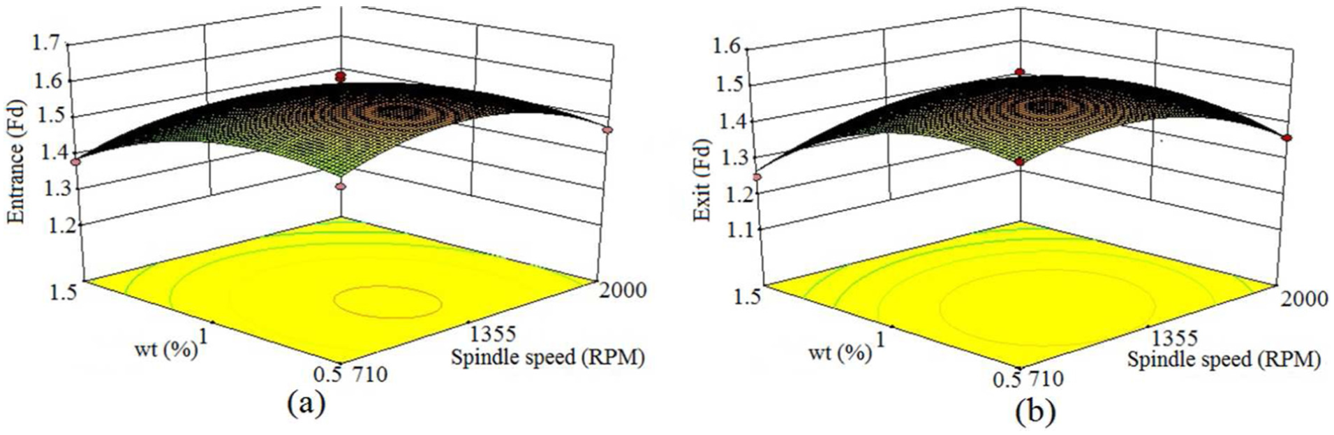
Delamination factor response graph as a function of the weight percentage of MWCNTs and spindle speed: (a) at entrance and (b) at exit.
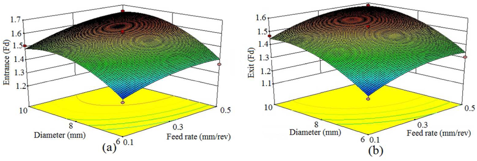
Delamination factor response graph as a function of drill diameter and feed rate: (a) at entrance and (b) at exit.
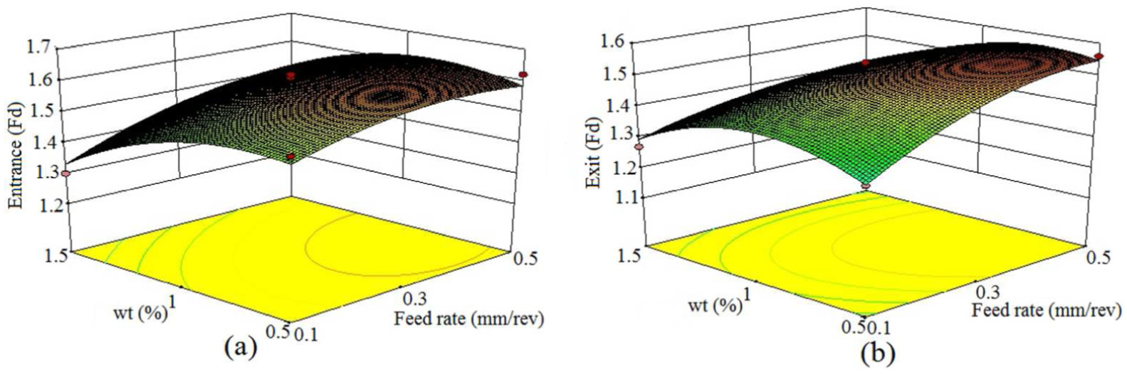
Delamination factor response graph as a function of the weight percentage of MWCNTs and feed rate: (a) at entrance and (b) at exit.
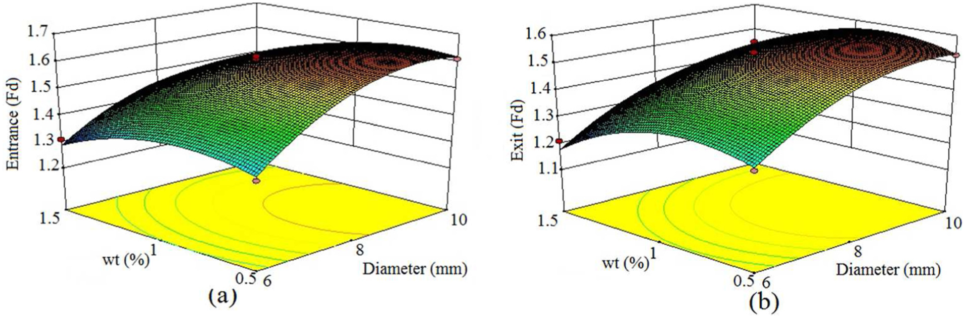
Delamination factor response graph as a function of the weight percentage of MWCNTs and drill diameter: (a) at entrance and (b) at exit.
Figure 8(a) and (b) shows that the delamination factor increases with an increase in feed rate. However, delamination factor decreases with increasing spindle speed. At a low feed rate (0.10 mm/rev) and high spindle speed (2000 r/min), lowest delamination factor was observed. As the feed rate increases, the damage behaviour around hole is like impact damage. As a result, delamination is high at high feed rate. However, when spindle speed increases, matrix material gets softened due to high cutting temperature. Figure 9(a) and (b) specifies the influence of spindle speed and drill diameter in the drilling of MWCNT–embedded epoxy/glass fabric nanocomposites. The figure illustrates that the same trend could be observed with respect to the spindle speed as discussed earlier. Delamination factor at the entrance and exit points goes up due to an increase in the drill diameter. The reason is an expansion of the contact area between the drill and the workpiece interface. As a result, there is a rise in the thrust force leading to more delamination. The lowest delamination factor is obtained at 6 mm of diameter and 2000 r/min of spindle speed.
Figure 10(a) and (b) demonstrates that the delamination factor at the entrance and the exit points diminishes as the weight percentage of MWCNTs increases. However, the effect of the spindle speed on the delamination factor is the same as discussed previously. The minimum delamination is obtained at 1.5 wt% of MWCNTs and 2000 r/min of spindle speed. As the weight percentage of MWCNTs increases, the strength, fracture toughness and flexural strength of the material increase as well. Due to an increase in the flexural strength, sticking capability between the fibres and resin enhanced, which in turns reduces delamination. At the exit side, delamination is less due to an increase in inter-laminar bonding strength. 1
Figure 11(a) and (b) presents the effect of drill diameter and feed rate on delamination factor in the drilling of MWCNT–embedded epoxy/glass fabric nanocomposites. As discussed previously, due to an increase in the drill diameter and feed rate, the delamination factor increases at the entrance and exit sides. The maximum delamination is measured at 10 mm of drill diameter and 0.5 mm/rev of feed rate. On the other hand, the smallest delamination factor is observed at 6 mm of diameter and 0.10 mm/rev of feed rate. Figure 12(a) and (b) shows the interaction between the weight percentage of MWCNTs and the feed rate in drilling of MWCNT-embedded epoxy/glass fabric nanocomposites. The rise in the feed rate increases the delamination factor. However, with an increase in the weight percentage of MWCNTs, the delamination factor decreases. The lowest delamination factor is obtained at 0.10 mm/rev of the feed rate and 1.5 wt% of MWCNTs. Figure 13(a) and (b) presents the interaction plot between the weight percentage of MWCNTs and the drill diameter. As discussed previously, the delamination factor decreases with an increase in the weight percentage of MWCNTs due to a rise in the flexural strength and the fracture toughness. However, the delamination factor at the exit side is lower than that of the delamination factor at the entry side. The effect of the drill diameter on the delamination factor maintains the same trend as discussed in Figures 8 and 10.
Surface roughness analysis
The surface roughness of holes was measured to study the effect of MWCNT loading in epoxy resin. It was measured using Surftest SJ-210 (Mitutoyo America Corp.). The surface roughness is a major parameter to minimize during machining operation, which can affect the performance of the part when subjected to fatigue load, precision fits and fastener holes. It occurs due to fibre fracture, pull-outs and cracking of matrices in pieces. Four measurements were taken at different sections of the holes and their average value was analysed. The experimental results of the surface roughness are presented in Table 2.
ANOVA was used to study significant parameters which have more influence on surface roughness. MWCNT was found to have the greatest influence on surface roughness followed by drill diameters and feed rate. Spindle speed has the least influence on surface roughness as presented in Table 8. Box–Behnken was used for modelling of surface roughness. The developed model is presented in equation (9), which was found to be suitable to predict the surface roughness value. The predicted results on the basis of the developed model are presented in Table 2. To signify the MWCNT loading on surface roughness, the micrograph of the holes was taken using FESEM technique at 0.10 mm/rev and 2000 r/min. The FESEM characterization established that as the MWCNT loading increases, debonding of the fibre and matrix reduces. From Figure 14(a), it can be observed that more debonding occurs between the fibres and matrix in 0.5 wt% MWCNT-loaded GFRP nanocomposites. However, at 1.0 wt% MWCNT, pull-outs of the fibres and fractured fibres were observed to be the minimum as shown in Figure 14(b). It can be clearly seen in Figure 14(c) that due to an increase in the MWCNT content, the bonding strength between the fibres and the matrix increases, which results in reduction in debonding. It can also be observed that tiny particles of the fibre are attached to the hole wall. From these figures, one could conclude that better surface of the hole could be obtained by increasing the MWCNT content.
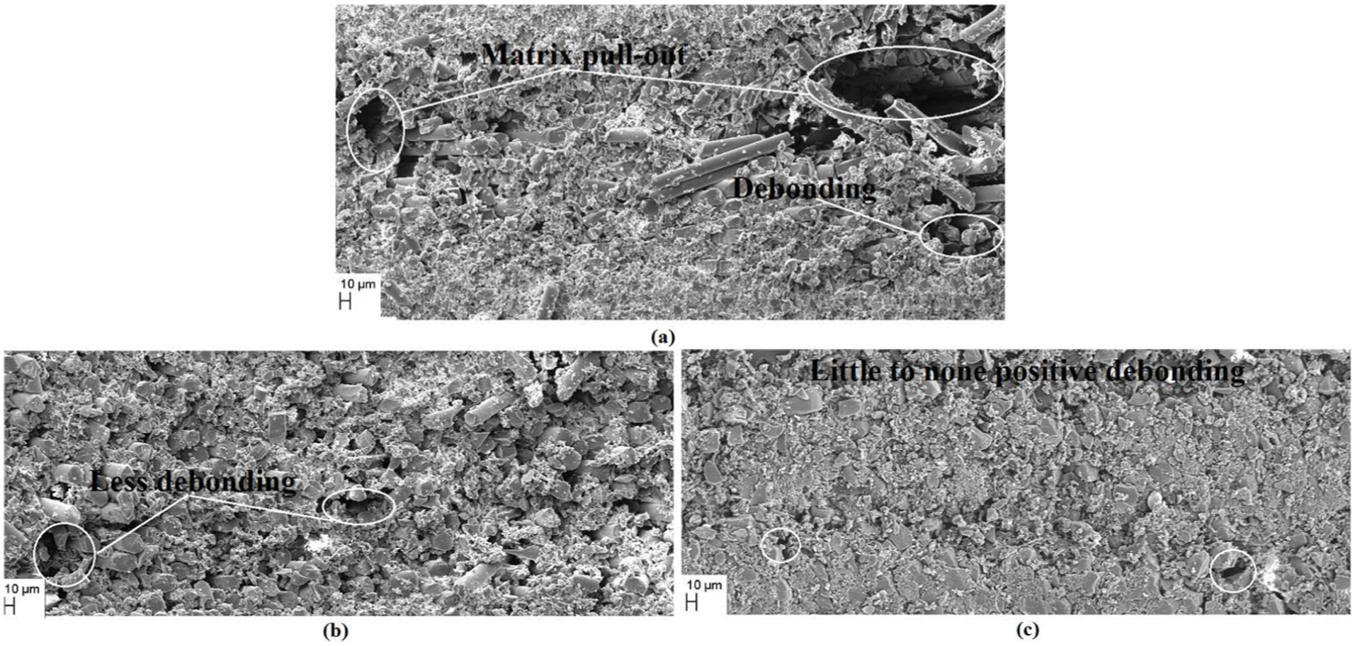
FESEM micrograph of drill hole wall: (a) 0.5 wt% MWCNT, (b) 1.0 wt% MWCNT and (c) 1.5 wt% MWCNT-embedded GFRP nanocomposite.
Influence of parameters on surface roughness
The three-dimensional response surface graph is presented in Figure 15. It can be seen that as the weight percentage of MWCNT and spindle speed increases, surface roughness decreases. However, with an increase in the feed rate and drill diameter, the surface roughness increases. From Figure 15(a), it can be observed that as the feed rate increases, the roughness of the hole increases as well. On the other hand, with an increase in the weight percentage of MWCNT, the surface roughness decreases. The reason is that at a higher feed rate, fracture is more violent as compared to a lower feed rate. From Figure 15(b), it can be seen that the surface roughness decreases with an increase in the weight percentage of MWCNTs. In a low percentage of MWCNT-loaded GFRP nanocomposites, the maximum value of surface roughness was measured due to generation of heat in drilling, which leads to softening of the matrix and formation of built-up edge on the hole wall at a higher spindle speed. However, the generated heat gets easily transferred because 1.5 wt% of MWCNT loading in epoxy increases the conductivity of GFRP nanocomposite materials. As a result, there is little chance to form built-up edge on the hole wall. Hence, at a higher spindle speed, the surface roughness is low.
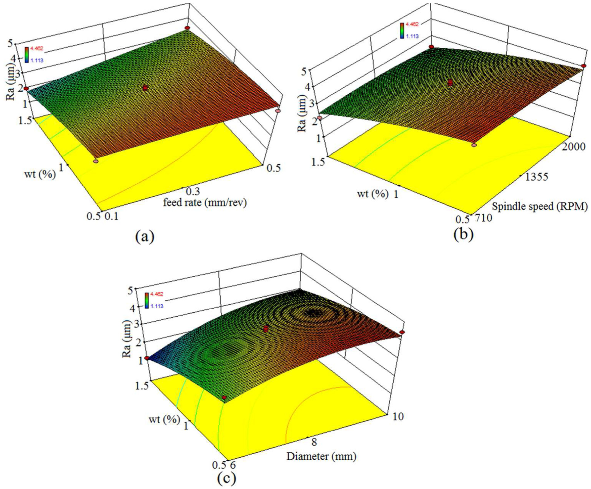
Effect of (a) feed rate, (b) spindle speed and (c) drill diameter on the surface roughness for varying amounts of MWCNT.
As the drill diameter increases, the surface roughness of the hole increases as well. The minimum value of surface roughness is measured in 1.5 wt% of MWCNT-loaded GFRP nanocomposites and with a drilled diameter of 6 mm, as shown in Figure 15(c). It has been observed that as the drilled diameter increases, the thrust force on the material increases due to a wider contact area. This leads to more debonding in the matrix and fibres. However, as the weight percentage of MWCNT increases, debonding gets reduced. It can be seen in the FESEM micrograph of hole, as presented in Figure 14.
Conclusion
The main objective of this study was to investigate the influence of the drilling parameters and weight percentage of MWCNTs in the drilling of MWCNT-embedded epoxy/glass fabric nanocomposites using solid carbide TiAlN-coated drills with different diameters. The experiments were based on Box–Behnken design. Nonlinear second-order models for delamination factor and surface roughness were developed using RSM technique. The conclusions from this study can be summarized as follows:
The mathematical models are developed for the study of delamination factors (at the entrance and exit sides) and surface roughness in the drilling of MWCNT-embedded epoxy/glass fabric nanocomposites. The developed nonlinear models are reasonably appropriate and could be used for prediction within the level of factors investigated.
The models are appropriate at 95% level of confidence within level considered.
The results indicate that the delamination factor at the entry and exit sides increases with an increase in the feed rate. On the other hand, due to an increase in the spindle speed, the delamination factor decreases.
Due to the addition of MWCNTs to the matrix, strength and fracture toughness of the GFRP nanocomposites get enhanced. As a result, the delamination at the entry side is reduced. The delamination factor at the exit side is lower than at the entry side. The delamination factor occurs at the exit side due to the failure of inter-laminar bonding. However, the addition of MWCNTs increases the inter-laminar bonding strength.
As the drill diameter increases, the contact surface of the material and the drills increases. As a result, the thrust force also increases during the drilling of MWCNT-embedded epoxy/glass fabric nanocomposites. It leads to an increase in the delamination factor. Hence, instead of bigger holes, smaller holes may be drilled.
MWCNTs have greater influence on surface roughness. The results indicate that an increase in the weight percentage of MWCNTs reduces surface roughness.
The surface roughness of the holes increases with an increase in the feed rate and drilled diameter.
As the weight percentage of MWCNT increases, the conductivity of the GFRP nanocomposites increases as well, which leads to a decrease in the chance of built-up edge formation on the hole wall. As a result, at 1.5 wt% loading of MWCNTs, a low value of surface roughness is measured.
Footnotes
Declaration of conflicting interests
The author(s) declared no potential conflicts of interest with respect to the research, authorship and/or publication of this article.
Funding
The author(s) received no financial support for the research, authorship and/or publication of this article.