
Abstract
In this work, the influence of multi-walled carbon nanotube is presented on laser drilling of multi-walled carbon nanotube–doped glass/epoxy polymeric nanocomposite. Multi-walled carbon nanotubes were dispersed in polymer matrix to improve the thermal conductivity and heat transfer characteristics of materials, which also reduces the divergence in decomposition temperature of matrix and glass fiber. Effect of carbon nanotube on laser drilling–induced damages was assessed by considering heat-affected zone, taper angle, and surface roughness as output parameters. Scanning acoustic microscopy showed the useful technique to examine the laser drilling damage around the hole by providing ply-by-ply damage analysis. In addition, scanning electron microscope provided more details to better analyze the machining quality of laser-drilled hole. Energy dispersive X-ray analysis provided the elemental analysis of charred material which is deposited on the hole wall. Obtained results indicate that the quality of hole was improved significantly due to addition of multi-walled carbon nanotube in polymer matrix.
Keywords
Introduction
Mainly glass fiber, carbon fiber, and aramid fiber are used as reinforcement in fiber-reinforced polymer composite material. The use of glass fiber reinforced polymer (GFRP) composite material increases considerably in automotive, aerospace, energy, defense, railway, and marine due to its high strength to weight ratio.1,2 Therefore, GFRP composite materials are used as a substitute for metals. For example, Bell Boeing V-22 Osprey military aircraft and B787 aircraft made up with 50% of composite content, 3 25% of composite parts uses in Airbus 380. 4 Generally, conventional drilling of GFRP composite material is used in industries although its application of thrust force on the composite material causes serious damages such as drilling-induced delamination, fiber push-out,5–7 fracture of fiber,5–8 cracking of matrix,5–9 and low surface finish. 10 During mechanical drilling, tool wear is the serious problem, which occurred due to brittle nature of glass fiber. However, as tool wear increases, the machining time and cost increase significantly.11–13 The use of non-tradition machining operations such as laser processing or abrasive water jet machining for composite materials increases because of non-contact machining operation.14,15 Laser processing offers several benefits over traditional drilling such as no tool wear, thrust force, delamination, and fiber push-out problem. 16 A detail summary of advantages, drawbacks, and desirability of laser machining are presented in Table 1. From Table 1, it can be seen that laser machining offers several advantages over the conventional machining, ultrasonic machining, and water jet machining. 17 However, the main challenge in laser drilling of GFRP material is to minimize the heat-affected zone (HAZ) and maintain the high drilling operation speed in order to reduce the cost. GFRP composite materials are different from that of conventional materials such as metals, ceramics, and polymer because of anisotropic behavior. 18 In fact, at high temperature, there is a large difference in material properties which causes the difficulties in laser processing. 19 Laser processing of materials is a thermal processes, though due to the large difference in thermal properties, some serious damages are occurred such as HAZ, matrix recession, and taper angle. 20 During the laser machining of GFRP laminates, initially, the ablation temperature may not cross the vaporization temperature of glass fiber, but more than the degradation temperature of matrix which leads to poor surface finish. 21 Mainly GFRP laminates represent a complex architecture, due to this reason anisotropic heat conduction of laminate is another cause of HAZ. Heat conduction in the direction of fiber is faster than traverse direction, which leads to non-uniform HAZ. The large difference in thermal conductivity of fiber and matrix makes tougher to obtain uniform HAZ.
Desirability of machining processes for fiber reinforced polymer composite material. 13
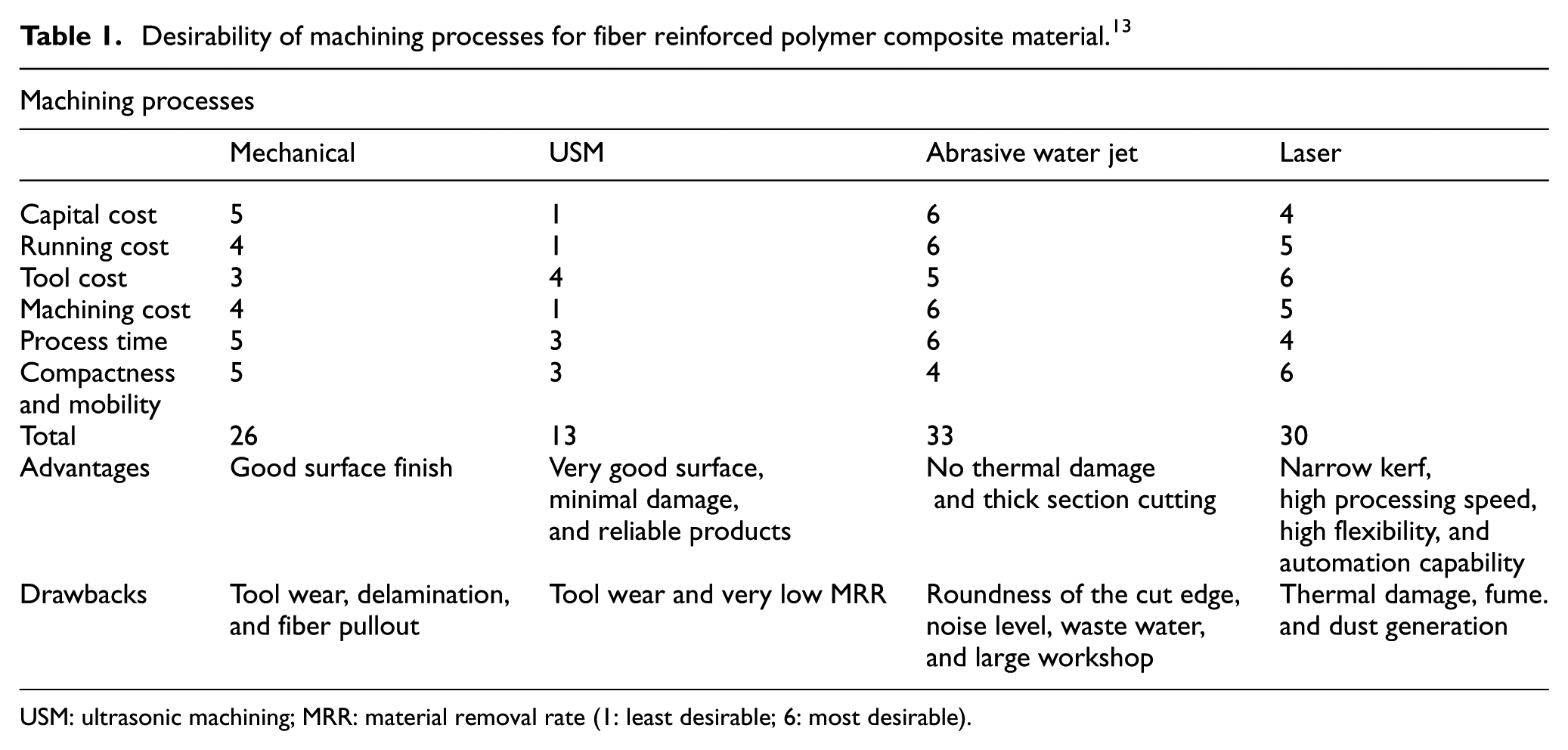
USM: ultrasonic machining; MRR: material removal rate (1: least desirable; 6: most desirable).
Many authors reported that laser parameters such as amount of power, scan speed, frequency, assisted gas pressure, and type of gas have an influence on HAZ, taper angle, and surface roughness during laser processing of polymeric materials.22–25 Laser power is the most effective parameter on the structure of HAZ during processing of GFRP composite materials. When low amount of laser power and plus repetition rate are used, less charred material and clear hole wall are observed. However, at high laser power, matrix is vaporized due to low vaporization temperature and glass fibers were melted. 26 Another serious damage during laser processing is taper angle. It can be minimized using high scan speed and frequency because of short interaction time of laser beam to the material. However, taper angle increases with increase in amount of power and assisted gas pressure. 27 Negarestani and Li 28 reported that assisted gas has been an influencing factor in laser processing of polymeric materials. They used three types of assisted gases namely oxygen, nitrogen, and argon and found that cutting quality was improved using inert gas with high pressure. To find out the effect of laser processing on surface quality of polymeric material, laser beam power and scan speed must be optimized to achieve superior surface quality and roughness value. Choudhury and Shirley 29 performed laser cutting of polymeric material namely polypropylene (PP), polycarbonate (PC), and polymethyl methacrylate (PMMA). They found that the surface roughness decreases as the amount of laser power, scan speed, and compressed air pressure increases. Choudhury and Chuan 30 performed a laser cutting operation on GFRP composite material. They observed surface roughness can be improved as the thickness of material and cutting speed increase; however, the effect of these parameters is not consistent.
Several authors have reported that HAZ and taper angle are the serious thermal damages during laser processing of polymeric materials. These are occurred because of large difference in thermal properties of fiber and matrix. If the divergence in thermal properties of constituent material minimizes, then HAZ and taper angle can be minimized. Thus, the dispersion of highly conductive nanoparticle in matrix could reduce the difference in thermal properties of fiber and matrix. Nagesh et al. 31 reported that using carbon black as nanofillers in matrix reduces HAZ and taper angle considerably. However, the uses of carbon black in excess amount in matrix may ruin the mechanical properties of laminates. Therefore, multi-walled carbon nanotubes (MWCNTs) are considered as potential nanofiller in matrix to reduce the divergence in thermal properties of fiber and matrix because of its high thermal conductivity and excellent mechanical properties. 32
In this work, an attempt is taken to reduce the HAZ and taper angle as well as to improve the surface finishing of hole by the dispersion of MWCNTs in polymer matrix. Four GFRP nanocomposite materials were prepared with different weight percentage of MWCNTs, that is, neat epoxy, 0.5 wt%, 1.0 wt%, and 1.5 wt% MWCNT-doped GFRP nanocomposites. Laser power, scan speed, and wt% of MWCNT are considered as main input parameters. However, HAZ, taper angle, and surface roughness are considered as output responses to assess the influence of MWCNT on laser drilling of MWCNT-doped glass/epoxy polymeric nanocomposite.
Experimental procedure
Material fabrication
The workpiece laminates were prepared using 12 layer of woven roven glass fiber of 600 gsm of stacking order [45/−45], [45/−45], [30/−60], [30/−60], [30/−60], [0/90] // [0/90], [30/−60], [30/−60], [30/−60] [45/−45], and [45/−45]. Calculated amount of MWCNTs (United Nanotech Innovations Pvt. Ltd., India) was added in epoxy to minimize the mismatch of thermal properties of constituent material. MWCNTs of different weight percentages such as 0 wt%, 0.5 wt%, 1.0 wt%, and 1.5 wt% was added to acetone with the help of Ultrasonic probe sonicator (Oscar Ultrasonic Pvt. Ltd., Mumbai, India) and sonicated for 30 min at 20 KHz to minimize the chances of agglomeration. Then, epoxy (Lapox L-12 ARL-12 Epoxy Resin, Atul Ltd., India) was added to the mixture and again sonicated for 30 min. The mixture of MWCNTs, acetone, and epoxy resin is heated at 80 C followed by magnetic stir for 60 min to remove the acetone. The MWCNTs-epoxy cool down at room temperature to avoid premature curing, and then hardener (Lapox K-6 AH-312, Atul Ltd., India) was added and mixed at 900 r/min for 10 min using mechanical stirring process. Hand lay-up technique was used for application of epoxy to the each layer of fiber, then material was pressurized in mold using vacuum bagging technique at 700 mm of Hg for 24 h (Figure 1). The prepared workpiece material has 50% of fiber volume fraction and the average thickness is around 5.40 mm.
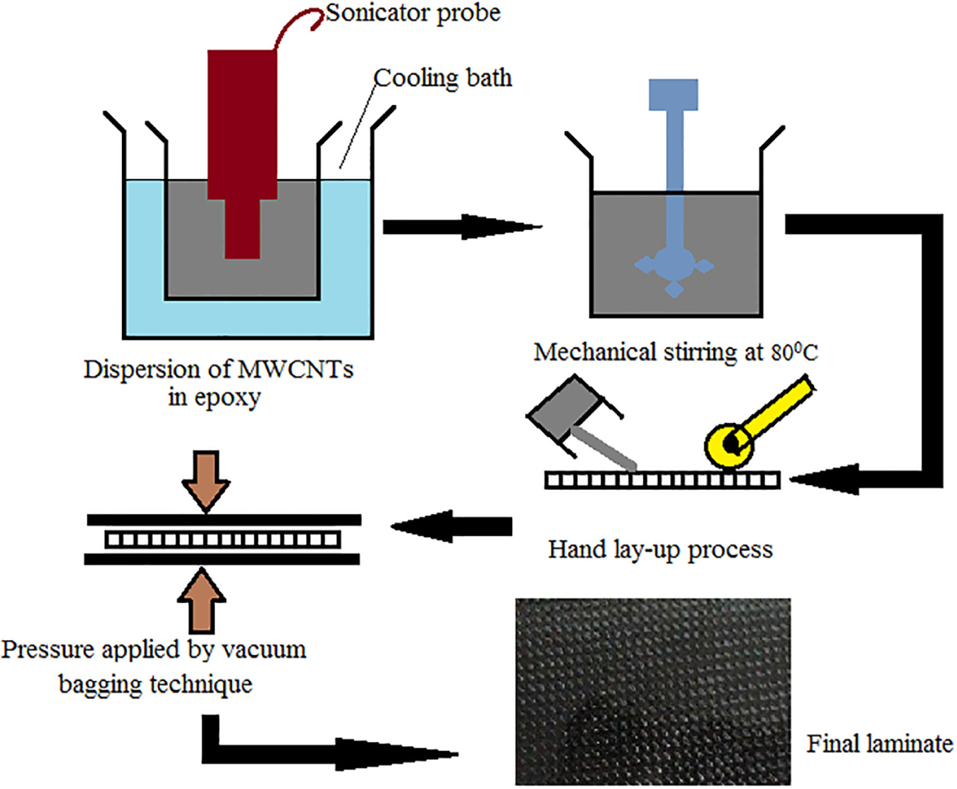
Schematic representation of material fabrication.
Laser equipment
A continuous mode fiber laser of maximum power 400 W and central emission wavelength of 1070 ± 10 nm were used for machining, which has maximum modulation rate of 100 KHz and central pulse width is less than 10 µs. The spot size for the focused laser beam is 100 µm. Lens focal length is 200 mm and distance between laminates and laser nozzle was maintained at 0.5 mm. Three axes computer numerical controlled (CNC) bed (150 × 150 × 100 mm3) was used for drilling of MWCNT-doped epoxy/glass fiber polymeric nanocomposite. Trepanning drilling technique was considered to perform the drilling of 8-mm-diameter hole in GFRP nanocomposite. The details of laser drilling setup are presented in Figure 2.
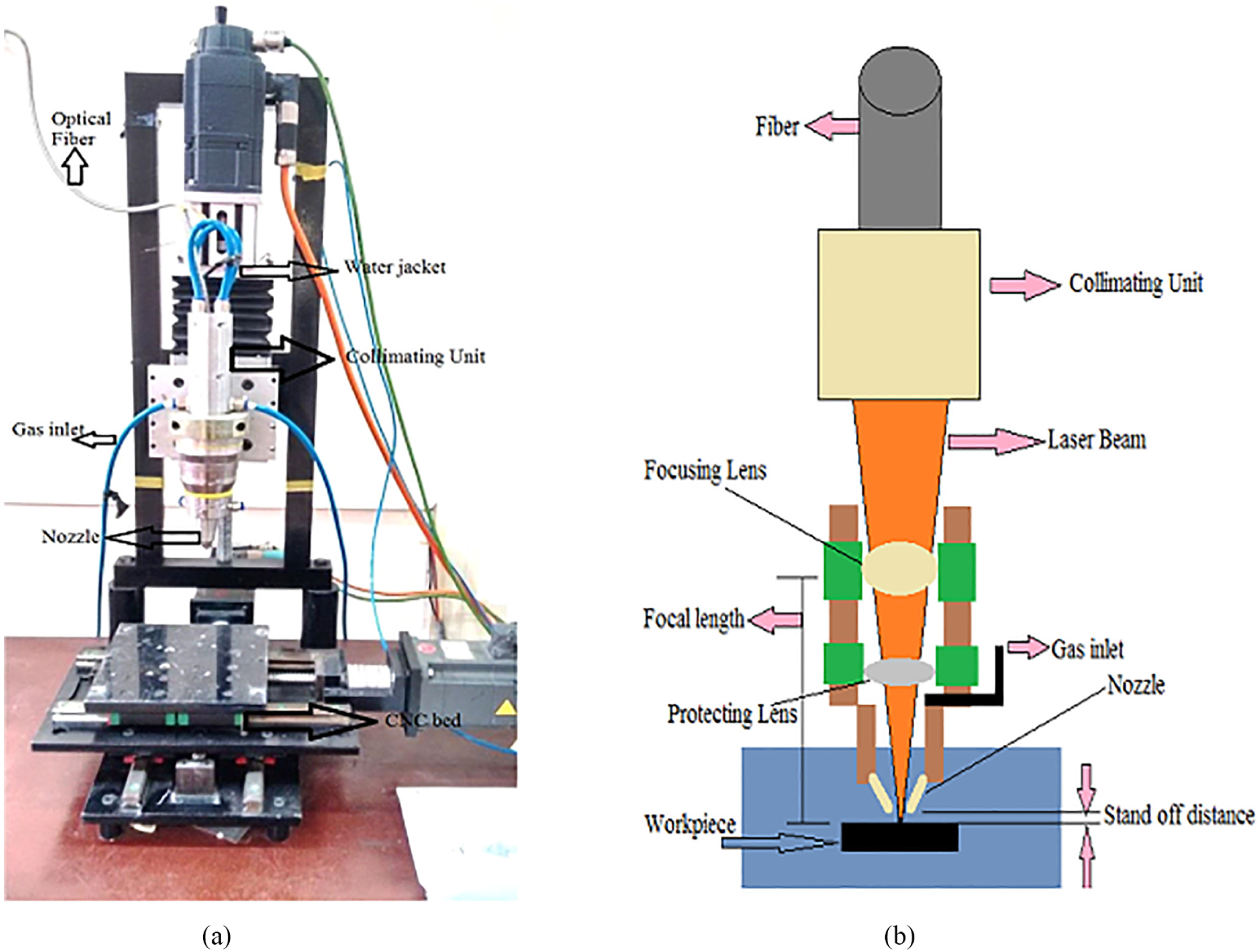
(a) Laser drilling machining system and (b) schematic of laser machine and workpiece arrangement.
Plan of experiment and measurement
For laser drilling, the most important parameters on which quality of hole depends are laser power (W) and scan speed (mm/min). In this experiment, these parameters are used to assess the influence of MWCNT (wt%) on output responses such as HAZ, taper angle, and surface roughness. Table 2 presents the parameters and their level used in this experiment. Test was conducted according to full factorial design, to find out the percentage contribution of MWCNT content and laser parameters on the output responses. Analysis of variance (ANOVA) was used to examine the more and less significant parameter on outcome. All set of experiments were conducted on 10 kg/cm2 pressure of N2 gas to aid in heat dissipation, and investigate the effect of laser power and scan speed while drilling MWCNT-doped glass/epoxy polymeric nanocomposite. Another experiment (at 360 W and 270 mm/min) was conducted to quantify the effect of assisted gas pressure on output responses at different pressures such as 6, 8, 10, and 12 kg/cm2. For each experiment, four (4) holes were drilled.
Laser drilling parameters and their level.
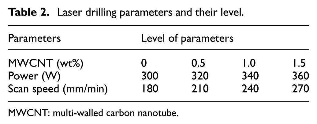
MWCNT: multi-walled carbon nanotube.
HAZ was measured using optical microscope. HAZ was evaluated on the basis of burnt surface around the hole. For each hole, four measurements were taken and their average values are considered for analysis. Taper angle was measured considering the top and bottom sides diameter of hole presented by Nagesh et al. 31 using equation (1)
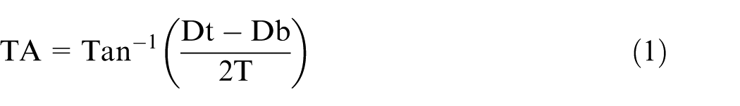
where TA denotes the taper angle, Dt and Db are the diameters at top and bottom of the hole, respectively, and T represents the thickness of material.
The hole diameter was measured on both side top and bottom face of material using image processing software (ImageJ 1.50), in which lower taper denotes the minimum wastage of materials. Schematic representation of HAZ and taper angle measurement is presented in Figure 3. Surface roughness (Ra) of hole is measured using contact-type stylus (SJ-210, Mutitiyo Inc., USA) profilometer. Cut-off length for measurement was fixed at 0.8 mm and moving speed was maintained 0.5 mm/s according to ISO 1997 standard. Profilometry was conducted from 2 to ply 11, first ply and last ply were not considered which is generally delaminated during laser drilling. For each hole, four measurements were taken at different cut section and their average values are consider for analysis.
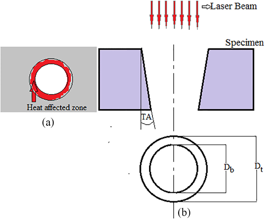
Measurement of (a) heat-affected zone and (b) taper angle.
Scanning acoustic microscopy
Scanning acoustic microscopy (SAM) (Model: V400; KSI, Germany) is an approach to characterizing laser drilling damage around the hole (as shown in Figure 4). To obtain the pre-eminent balance between quality of image and depth of imaging, 50 MHz non-contact transducer was chosen for composite materials which provide better visualization of ply-by-ply damage. The ultrasonic sound waves are transmitted from transducer to the GFRP laminate through a coupling medium (usually water). Grey scale images are developed based on amplitude and flight time of reflected waves. In this technique, X-scan was used to examine the ply-by-ply damage analysis along the depth of machined hole.
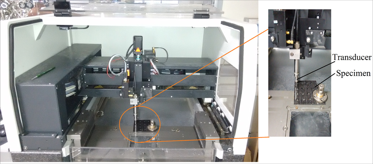
Scanning acoustic microscopy setup.
Results and discussion
Effect of MWCNTs on HAZ
During laser drilling of GFRP material, serious damage occurred due to thermal effects, which results in the alternation of microstructure and/or mechanical properties of GFRP laminates. HAZ is the serious thermal damage around the hole during laser processing of GFRP laminates.
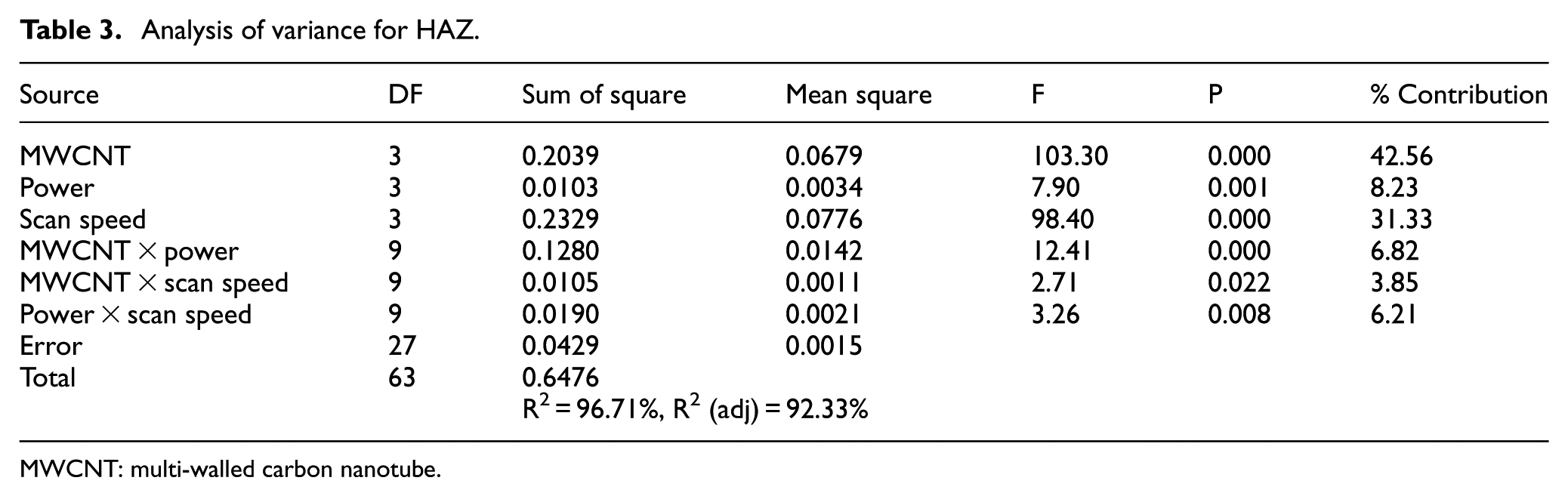
The ANOVA results for HAZ is presented in Table 3, and the obtained results indicate that scan speed and wt% of MWCNT are more significant on HAZ at the 95% level of confidence; however, laser beam power is less significant on HAZ. The ANOVA results also indicate the “F” values of the input parameters obtained from experimental results are 103.30, 7.90, and 98.40 for wt% of MWCNT, laser beam power and scan speed, respectively. It can be seen that wt% of MWCNT and scan speed are more effective parameter on HAZ; however, laser beam power is less effective in this laser drilling tests. Another interesting result could be obtained from ANOVA is that the interaction term is also significant on HAZ, in which, the interaction of wt% of MWCNT and laser power is more effective on the HAZ.
Analysis of variance for HAZ.
MWCNT: multi-walled carbon nanotube.
Figure 5 presents the interaction plot of HAZ, in which effect of MWCNT, as well as laser parameters such as laser beam power and scan speed, is presented. From Figure 5(a), it can be seen that HAZ increases with laser power, which is in good agreement with the results of Davim et al. 21 This phenomenon could be occurred due to higher incident energy at high laser beam power, which causes accumulation of heat at cutting zone. However, increasing wt% of MWCNT in polymer matrix HAZ reduced considerably. This reduction can be estimated by approximately 22% at high laser power. The reason is that when amount of MWCNT increases, thermal conductivity of polymer matrix increases which in turn reduces the thermal focus. Dispersion of MWCNT favors the thermal propagation in the vicinity of the machining area. Thereby, the decomposition temperature of polymer matrix increases, consequently reduced the divergence in thermal properties of glass fiber and matrix, which reduces the decomposition of matrix.
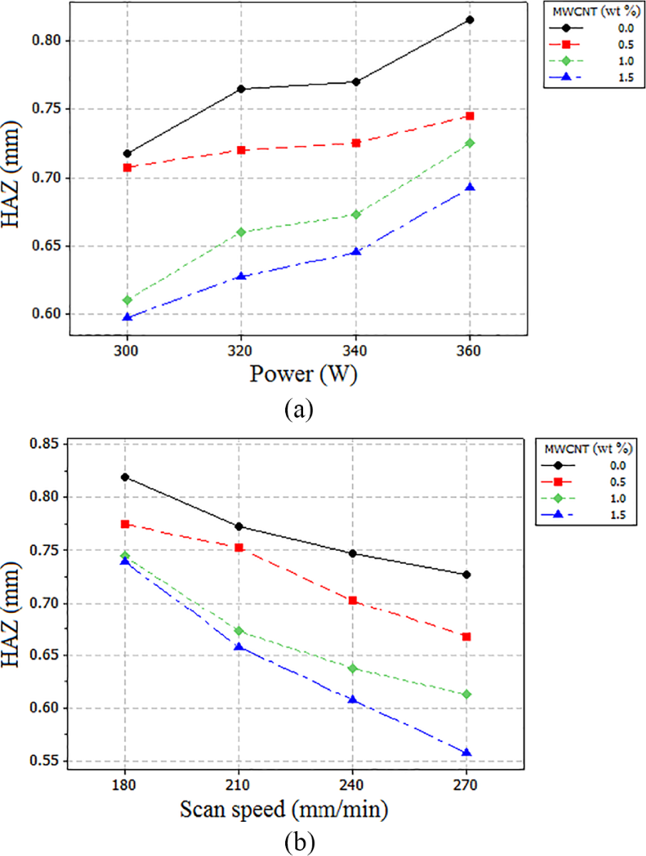
Effect of (a) laser power and (b) scan speed on HAZ for various amount of MWCNT.
From Figure 5(b), it can be seen that for different wt% of MWCNT, the HAZ around the hole decreases when scan speed increases. Due to reduction in interaction time between laser beams and GFRP materials, less time is available for the development of HAZ as there is less heat accumulation or incidental energy. Figure 6 denotes the micrograph of machined hole taken at 300 W and 270 mm/min for various amount of MWCNT. It can be seen that as wt% of MWCNT increases, HAZ decreases, which is in good agreement with experimental finding.
(a) Demonstration of HAZ for neat GFRP composite material, (b) demonstration of HAZ for 0.5 wt% MWCNT-doped GFRP nanocomposite material, (c) demonstration of HAZ for 1.0 wt% MWCNT-doped GFRP nanocomposite material, and (d) demonstration of HAZ for 1.5 wt% MWCNT-doped GFRP nanocomposite material.
Effect of MWCNTs on taper angle
Development of taper kerf during laser processing of GFRP composite material is the major problem. In this study, taper angle is considered to be one of the main quality factors of laser-drilled hole. To measure the hole taper, top face and bottom face diameters were measured using the technique of image processing by utilizing ImageJ 1.50 public domain software. In this study, thickness of workpiece materials is constant. Processing parameters such as amount of laser power and scan speed could affect the taper angle in the drilling of MWCNT-doped glass/epoxy polymeric nanocomposite.
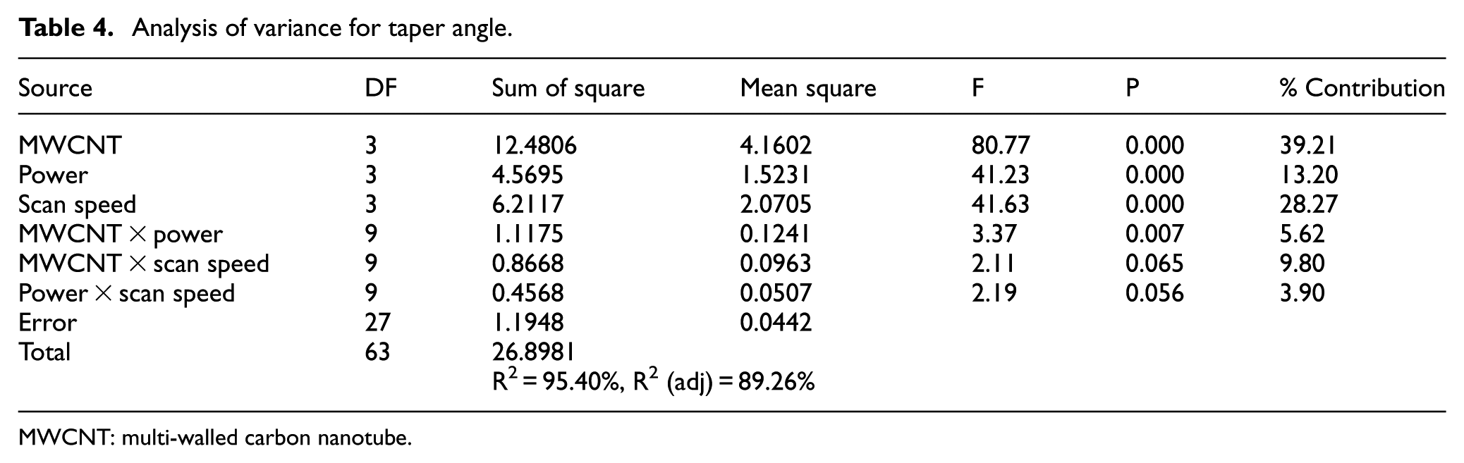
The ANOVA results of taper angle, obtained in the laser drilling of MWCNT-doped glass/epoxy polymeric nanocomposite, are presented in Table 4. Results indicate that all processing parameters such as wt% of MWCNT, laser power, and scan speed have statistically significant on taper angle at the 95% level of confidence. The obtained “F” values of drilling parameters from experimental results are 80.77, 41.60, and 41.23 for wt% of MWCNT, scan speed, and laser beam power, respectively. It can be seen that the wt% of MWCNT is the most significant parameter on taper angle followed by scan speed and laser power. In case of interaction of parameters, only MWCNT and power are significant and effective on taper angle at given level of confidence.
Analysis of variance for taper angle.
MWCNT: multi-walled carbon nanotube.
Figure 7 indicates the evolution of taper angle with processing parameters such as laser power and scan speed. From Figure 7(a), it can be noted that taper angle increases with amount of laser power; however, as wt% of MWCNT increases in polymer matrix, taper angle decreases. Lower taper angle observed at 300 W in the drilling of 1.5 wt% of MWCNT-doped glass/epoxy polymeric nanocomposite. The reason is that larger amount of heat is produced at high laser power, which increases the taper angle. In MWCNT-doped glass/epoxy polymeric nanocomposite material, heat is accumulated around the hole and easily transferred through the material due to improvement in heat transfer characteristics, therefore, less chance is available to decompose the matrix due to incident heat.
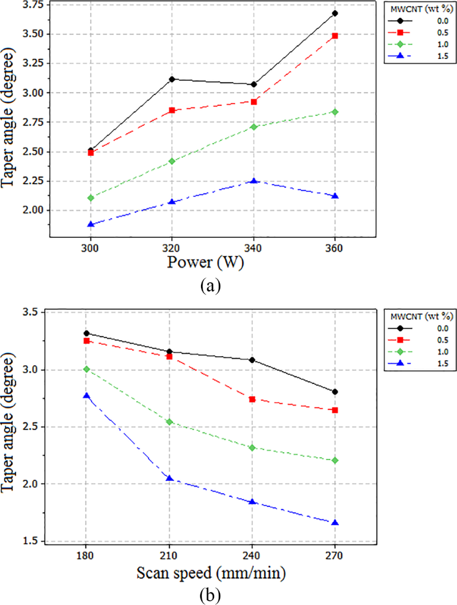
Effect of (a) laser power and (b) scan speed on taper angle for various amount of MWCNT.
Moreover, in case of neat epoxy/glass fiber reinforced composite material, heat accumulation around the hole is maximum which leads to decomposition of the matrix; hence, maximum difference in top face and bottom face diameter was observed. Figure 7(b) indicates that as scan speed increases, taper angle decreases. It is due to less interaction time of laser beam with workpiece material. As interaction time increases, absorption of energy increases which leads to maximum removal of material; therefore, maximum taper is observed at low scan speed. Larger taper angle was observed in neat epoxy/glass fabric composite material at 180 mm/min; however, in 1.5 wt% of MWCNT-doped glass/epoxy polymeric nanocomposite, lower taper angle was observed. It appears that, when MWCNT content in polymer matrix increases, decomposition temperature of matrix enhanced; therefore, decomposition of matrix reduced which in turn taper angle decreases.
Effect of MWCNT on surface roughness of hole
Surface roughness (Ra) measurement for laser drilling of MWCNT-doped glass/epoxy polymeric nanocomposite was performed on the 8-mm hole produced after laser drilling. Surface roughness of hole is another important parameter that represents the quality and accuracy of laser-drilled hole.
The ANOVA result of surface roughness of hole in the laser drilling of MWCNT-doped glass/epoxy polymeric nanocomposite is presented in Table 5. It can be noted that all processing parameters such as wt% of MWCNT, laser power, and scan speed are significant at 95% level of confidence. The obtained “F” values for parameters from experimental results are 199.20, 57.08, and 26.42 for wt% of MWCNT, laser power, and scan speed, respectively. Another interesting result obtained from ANOVA is that the interaction processing parameters would be effective on the surface roughness of hole at chosen level of confidence.
Analysis of variance for surface roughness.
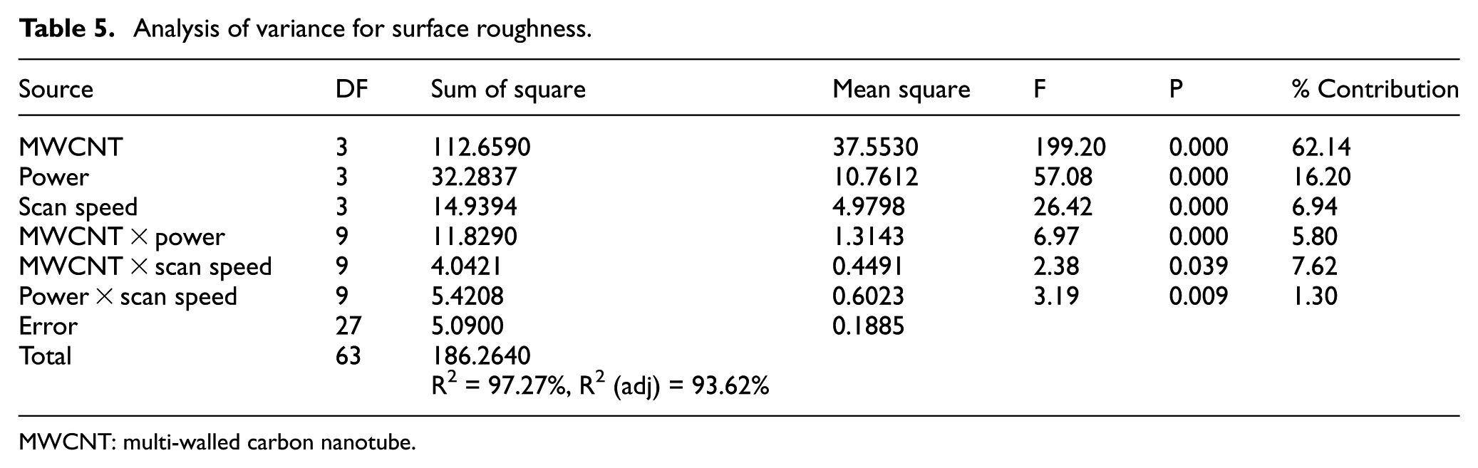
MWCNT: multi-walled carbon nanotube.
From Figure 8(a), it can be observed that surface roughness decreases as MWCNT content increases in polymer matrix. However, surface roughness increases with laser power which is consistent with Ghany and Newishy. 33 The reason is that, at high amount of laser power, matrix disintegrated first due to its low decomposition temperature, leaving protruded fiber on cut surface which increases the surface roughness. Moreover, due to increase in MWCNT content in polymer matrix, fiber and matrix were decomposed together; therefore, chance of cave formation minimizes, which in turn results in smoother surface obtained at 1.5 wt% MWCNT-doped GFRP nanocomposite.
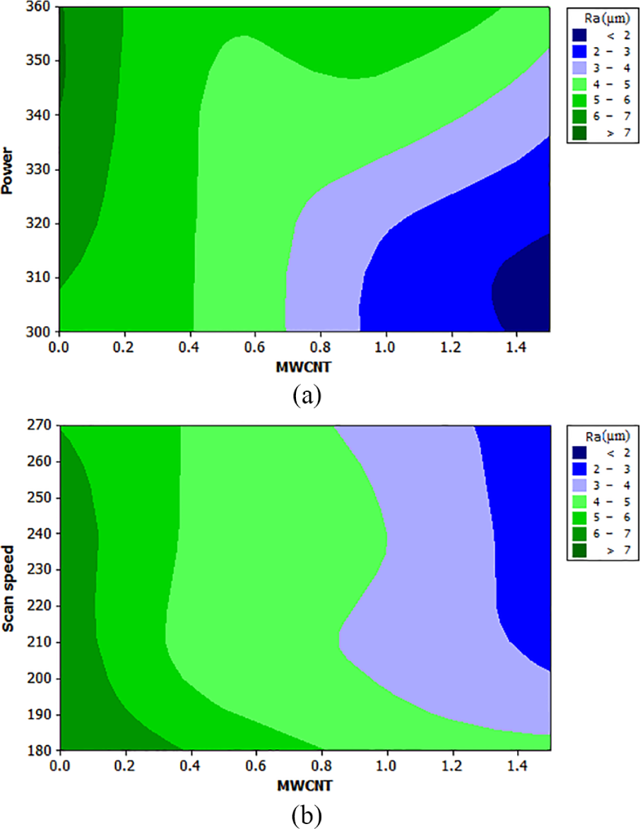
Effect of (a) laser power and (b) scan speed on surface roughness for various amount of MWCNT.
Figure 8(b) presents the contour plot of MWCNT and scan speed on surface roughness. It indicates that surface roughness decreases as the scan speed increases and this result is consistent with Chen. 34 The results indicate that at low scan speed, the matrix vaporized completely and burnt due to large interaction of laser beam with workpiece material, resulting in charred deposited on surface which is responsible for poor surface finish. Moreover, at high scan speed and 1.5 wt% MWCNT, vaporization of matrix and severing of fibers were impeccable, resulting in better surface finish.
Effect of assisted gas pressure
Assisted gas pressure is an essential factor in laser drilling of MWCNT-doped glass/epoxy polymeric nanocomposite material to protect the optics, remove charred material decomposition, and also add heat dissipation. To examine the effect of assisted gas pressure on HAZ, taper angle, and surface roughness of hole, materials were drilled at 360 W of laser power and 270 mm/min of scan speed on different gas pressure. For each experiment, four holes were drilled and their results corresponding to assisted gas pressure are presented in Figure 9.
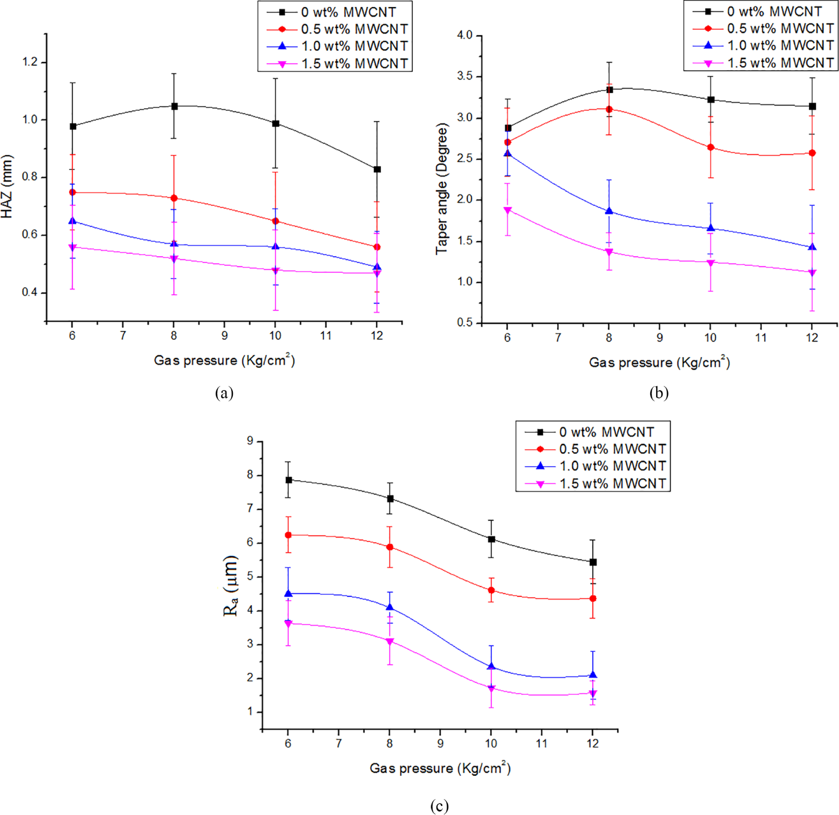
Effect of assisted gas pressure on (a) HAZ, (b) taper angle, and (c) surface roughness for different wt% of MWCNT.
Figure 9(a) indicates the influence of assisted gas pressure on HAZ of laser drilling for different specimens at 360 W and 270 mm/min. It has been observed that variation of HAZ in neat epoxy/glass fiber composite material is not consistent. However, in MWCNT-doped glass/epoxy nanocomposite material variation of HAZ with gas pressure is almost consistent. It can be seen that as gas pressure increases, HAZ decreases in case of 1.0 wt% and 1.5 wt% MWCNT-doped glass/epoxy polymeric nanocomposite. This result can be explained by the fact the reduction in matrix recession at high pressure. At low power, melting of material is dominant on material removal mechanism; however, at high power, vaporization of material is dominated on material removal mechanism. The assisted gas pressure increases the removal of material at high power due to vaporization mechanism and consequently heat dissipation increases at high pressure which in turn reduces the formation of HAZ.
Figure 9(b) presents the effect of assisted gas pressure on taper angle at 360 W and 270 mm/min. it can be seen that, as gas pressure and content of MWCNT increase, taper angle decreases. At high pressure, material was removed easily and also nitrogen gas which assisted in heat dissipation, therefore, lower taper was observed. Neat epoxy and 0.5 wt% of MWCNT-doped glass/epoxy polymeric nanocomposite material followed almost same trend; however, maximum taper angle was observed in neat epoxy/glass fiber composite material. It indicates that matrix decomposes first due to low decomposition temperature (400 °C–600 °C) and flushed out with high pressure which is responsible for wider angle. As content of MWCNT increases, heat transfer characteristic as well as divergence in vaporization temperature reduces; therefore, minimum taper angle could be obtained in 1.5 wt% of MWCNT-doped glass/epoxy polymeric nanocomposite.
Figure 9(c) indicates the effect of assisted gas pressure on surface finishing in drilling of MWCNT-doped glass/epoxy polymeric nanocomposite. It is noted that smoother surface could be obtained with increasing pressure and MWCNT content. At high pressure, the decomposition of charred material on surface is minimum. Moreover, due to addition of MWCNT in polymer matrix, decomposition temperature of matrix increases, thus fiber not only melts (as seen in neat epoxy/glass fiber composite material) but also decomposes with matrix, resulting in minimum protruded fiber on hole wall; therefore, lower surface roughness observed in 1.5 wt% MWCNT-doped glass/epoxy polymeric nanocomposite.
Ply-by-ply damage analysis
As formerly mentioned, X-scan was performed on MWCNT-doped glass/epoxy polymeric nanocomposite materials which indicates significantly lower damage at 1.5 wt% of MWCNT reinforcement in matrix. During X-scan, as thickness of scan increases, weak reflection was observed. Thus, in order to get proper analysis, X-scan was performed on bottom side by flipping the laminates. X-scan was performed on hole machined at 360 W and 270 mm/min for various wt% of MWCNT-doped GFRP nanocomposite materials.
Table 6 presents the ply-by-ply damage development of MWCNT-doped GFRP nanocomposite material due to HAZ. The top image shows the laser beam entry side, while the bottom image indicates the laser beam exit side. It can be seen that HAZ around the hole decreases as dispersion of MWCNT in polymer matrix increases. This could be due to less divergence in decomposition temperature of fiber and matrix. MWCNT helps to improve the heat transfer characteristic of material due to its high thermal conductivity behavior, which reduces heat accumulation around the cut section of hole. Thus, in case of 1.5 wt% of MWCNT-doped GFRP nanocomposite, low disintegration of matrix is observed as compared to neat epoxy/glass polymer composite material. However, the HAZ at bottom is more than the top, due to cooling effect of N2 as assisted gas.
Demonstration of ply-by-ply damage analysis.
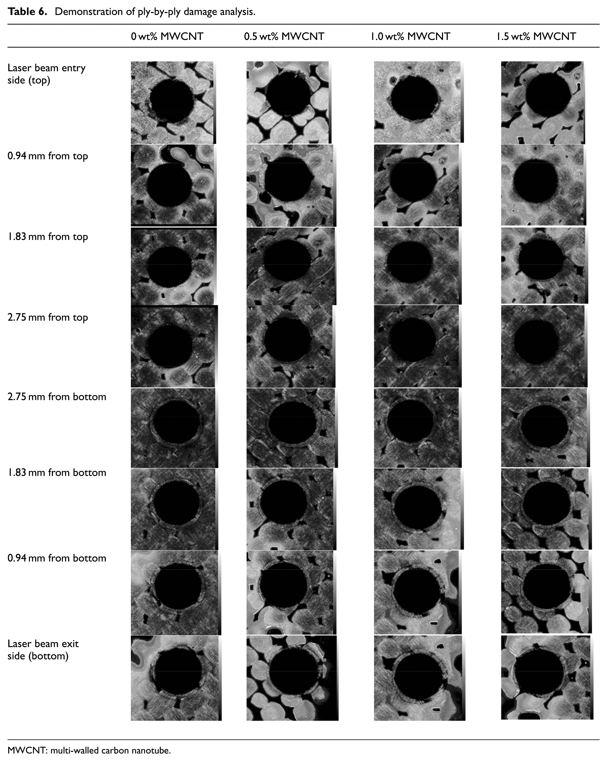
MWCNT: multi-walled carbon nanotube.
SEM and energy dispersive X-ray analysis of drilled hole
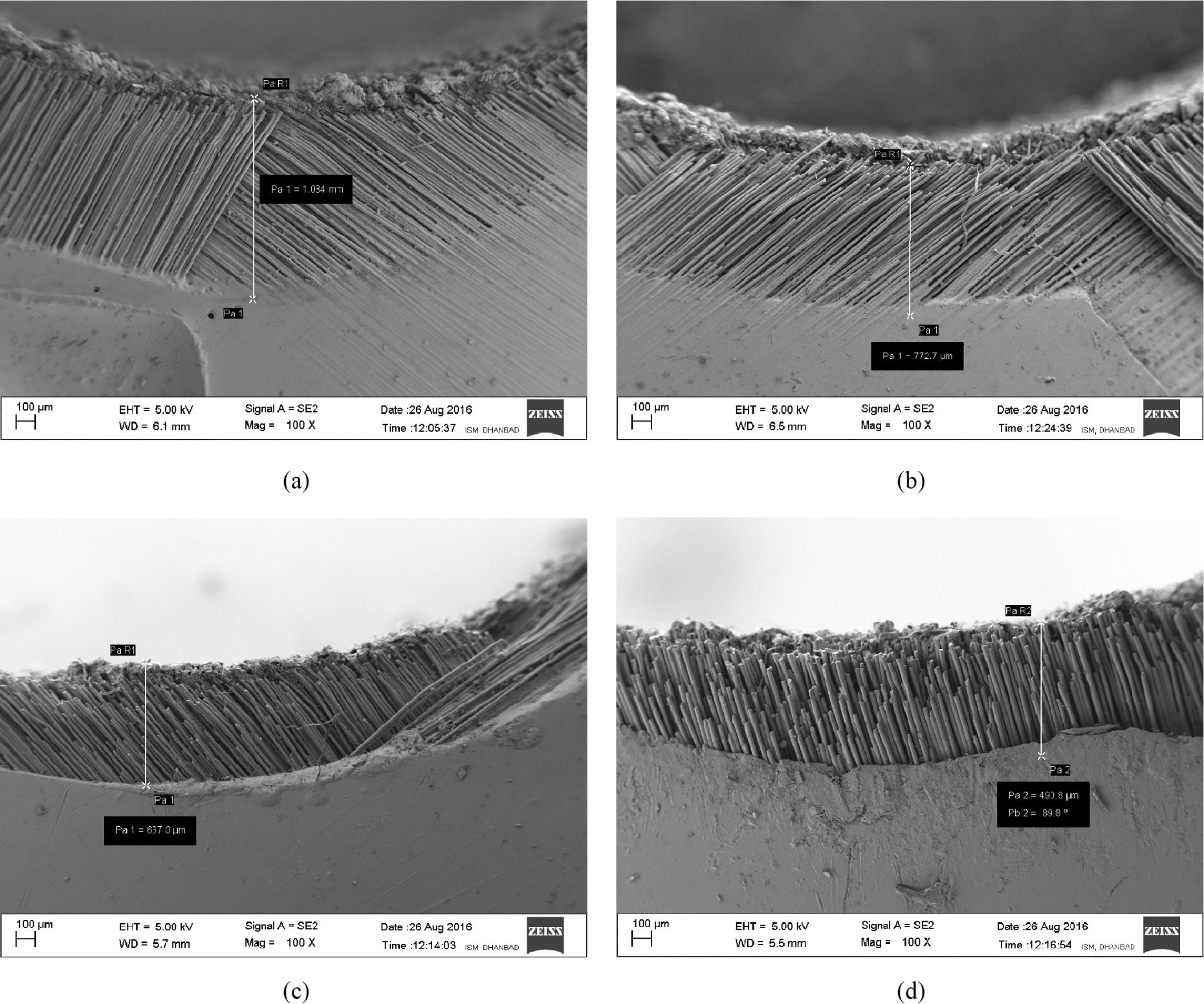
Figure 10 presents the micrograph of hole wall drilled at 300 W of laser beam power and 270 mm/min of scan speed. It can be seen that some of the fiber ends of neat epoxy/glass fiber composite material appeared like mushroom heads sticking out of matrix due to incident of laser beam on material. Polymer matrix disintegrated first due to low decomposition temperature; however, at same energy, fibers were melted into droplets and fused together as shown in Figure 10(a). Although, in case of 0.5 wt% MWCNT-doped GFRP nanocomposite, thick char deposited at entry side, swelling of fiber and central cavity on fiber ends were observed as depicted in Figure 10(b). Moreover, in case of 1.0 wt% of MWCNT-doped GFRP nanocomposite laminates, less swelling of fiber and thin char observed as presented in Figure 10(c). Figure 10(d) indicates the micrograph of 1.5 wt% of MWCNT-doped glass/epoxy polymer nanocomposite, in which very thin charred material and less protruded fibers are observed. The reason is that the decomposition temperature of matrix increases due to addition of MWCNT which in turn fiber and matrix disintegrated together.
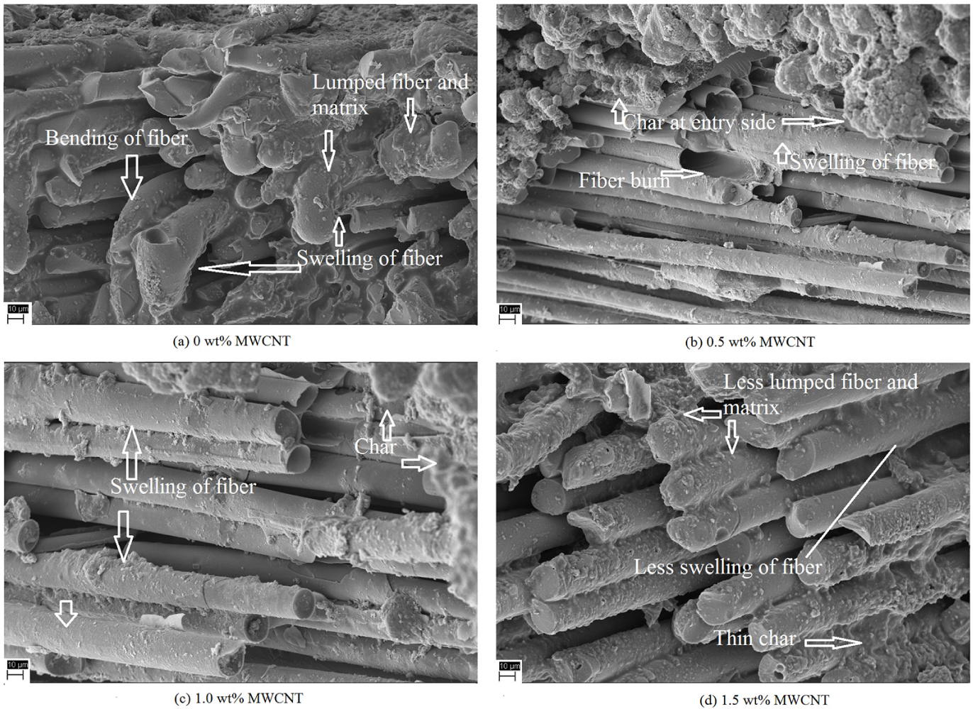
Micrograph of hole wall of various amount of MWCNT taken at 360 W and 270 mm/min.
Energy dispersive X-ray analysis (EDAX) analysis was performed to examine the composition of char material deposited on hole wall (Figure 11). For reference, elemental analysis of neat epoxy/glass fiber composite materials was also investigated, which is presented in Figure 11(a). In the elemental analysis of all specimens, highest wt% of carbon observed on hole wall, due to disintegration of matrix into carbon or graphite. After carbon, oxygen was found in high wt% due to formation of oxide during laser processing of GFRP laminates. From Figure 11, it can be seen that, as wt% of MWCNT increases, the wt% of silicon and calcium increases, which is an evident to the maximum decomposition of fiber at 1.5 wt% of MWCNT content as shown in Figure 11(d). Other elements such as silicon, calcium, magnesium, aluminum, and sodium are found mostly in oxide form due to composition of glass fiber (SiO2, 52 wt%; Al2O3, 15 wt%; CaO + MgO, 22 wt%; and Na2O, 2 wt%).
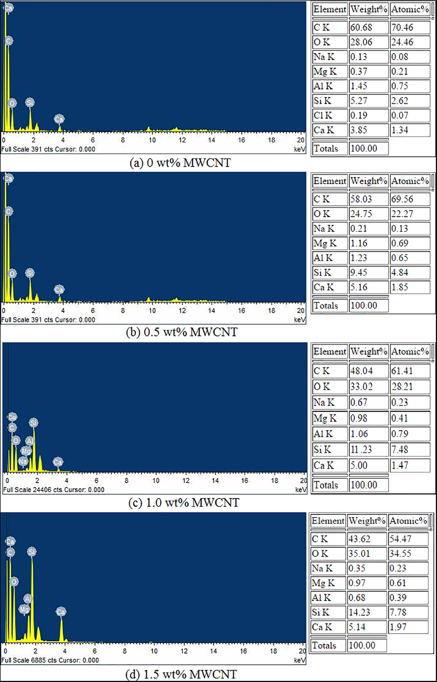
EDAX analysis of charred material of hole wall.
Conclusion
Following are the major conclusions drawn from the experimental investigation in laser drilling of MWCNT-doped glass/epoxy polymer nanocomposite:
The behavior of GFRP composite material in laser drilling is different from that of polymeric materials as well as metals, due to inhomogeneous thermal properties. Differences in thermal conductivity of glass fiber and matrix led to uneven melting and vaporization of materials.
Addition of MWCNT in polymer matrix improved the decomposition temperature of matrix; therefore, the HAZ, taper angle, and surface roughness of hole significantly reduced.
HAZ increases with amount of laser power due to heat accumulation at cut section which disintegrated polymer matrix easily. However, decreases as weight percentage of MWCNT in polymer matrix increase. As scan speed increases, HAZ was reduced due to minimum exposure of workpiece material to the laser beam. Moreover, slight difference in HAZ was observed with increasing assisted gas pressure in case of MWCNT-doped glass/epoxy polymer nanocomposite.
Laser parameters (laser power, scan speed, and assisted gas pressure) affect the taper angle considerably. Taper angle increases with laser beam power, however, decreases with increase in wt% of MWCNT, scan speed, and assisted gas pressure.
As far as the surface qualities are concerned in laser drilling, wt% of MWCNT plays important role in the improvement of surface finish. Moreover, surface finish was improved with increasing scan speed and assisted gas pressure; thus, for smoother surface, scan speed has to be regulated and optimized. However, surface roughness increases with laser power.
Footnotes
Acknowledgements
Authors would like to thank Micro- and Nano-Characterization facility, CENSE at IISc Bangalore for allowing the use of scanning acoustic microscopy (SAM).
Declaration of conflicting interests
The author(s) declared no potential conflicts of interest with respect to the research, authorship, and/or publication of this article.
Funding
The author(s) received no financial support for the research, authorship, and/or publication of this article.