
Abstract
The tool–workpiece interactions when a single-point diamond cutting tool with specific tool edge geometry is made to contact with a copper workpiece are evaluated by the molecular dynamics simulations under different temperatures, boundary conditions and model sizes for ultra-precision microcutting and in-process surface form measurement based on a force sensor–integrated fast tool servo. It is confirmed that the proposed multi-relaxation time method is effective to stabilize the workpiece molecular dynamics model over a wide temperature range up to the room temperature under which a practical microcutting and on-machine surface form metrology process are conducted. The boundary condition and model size of the molecular dynamics model are then optimized to make reliable and cost-effective simulations for evaluation of the elastic–plastic transition contact depth and the corresponding contact force when a diamond tool with a practical edge sharpness of up to 30 nm is employed for microcutting and on-machine surface form metrology.
Keywords
Introduction
Microcutting by utilizing fast tool servo (FTS) is an important technology for precision manufacturing of complex ultra-precision surfaces and micro-structured surfaces.1–6 The FTS-based microcutting is a complicated process, in which the materials are removed at a high rate using a sharp single-point diamond tool with an edge sharpness larger than 10 nm. 7 Although the FTS and the advanced machine tool technologies have been well developed to realize a nanometric or even subnanometric positioning resolution for the diamond cutting tool with respect to the workpiece surface, 8 the form accuracies of the fabricated surfaces are influenced by a number of factors in geometrical, mechanical and chemical aspects.9–11 The measurement of the surface form of the fabricated workpiece is thus an important issue for assurance of the fabrication accuracy. It is also expected to carry out the surface form metrology on the machine tool without removing the workpiece from the machine for improving the measurement accuracy and efficiency.12–14
On-machine surface form metrology is often carried out by mounting a commercial stylus profiling instrument, which is referred to as the stylus profiler, on the machine tool.15,16 In such a measurement, the scanning stage of the profiler and/or the moving axes of the machine tool are employed to provide scanning motions for the stylus probe, which can be a diamond tip with a micrometer-order radius or a ruby ball with a millimeter-order radius, to trace over the workpiece surface. The vertical displacement of the stylus probe, which is detected by the displacement gauge of the profiler, provides the height information of the surface profile. A state-of-the-art commercial stylus profiler can reach a subnanometric resolution in the vertical direction, which is compatible to the positioning capability of an ultra-precision diamond turning machine. The robustness of the stylus profiler to workpiece surface and environmental conditions also assure the reliability of the on-machine measurement results.
On the other hand, one of the most important motivations for on-machine surface form metrology is to feedback the measurement data to the cutting process for the purpose of compensation fabrication. From this point of view, it is necessary to accurately identify the tip position of the stylus probe with respect to that of the cutting edge of the diamond tool, which is extremely important for complex surfaces and micro-structured surfaces with steep slopes and highly curved features since a slight difference between the position of measurement and that of fabrication can cause a large error in the result of the compensation fabrication. This makes it difficult for applying the conventional type of on-machine measurement, where the measurement probe is physically separated from that of the cutting tool, to ultra-precision fabrication of complex surfaces and micro-structured surfaces with requirements of submicrometric or higher accuracies.
The authors have developed a new technology of on-machine surface form metrology using a force sensor–integrated fast tool servo (FS-FTS) as the stylus probe. 17 After the designed surface form is fabricated on the workpiece with the cutting tool controlled by the FS-FTS and the machine tool axes, the workpiece surface is scanned with the same cutting tool using the machine axes to generating the scanning motions. The contact force between the cutting tool and the workpiece surface is monitored by the FS of the FS-FTS during the scanning. The position of the cutting tool tip along the depth of cut direction is servo-controlled with the piezoelectric (PZT) actuator of the FS-FTS in such a way that the contact force is kept to be constant value, which corresponds to the measuring force of a stylus profiler. The servo-controlled PZT motion is measured by the displacement sensor of the FS-FTS. The surface form of the workpiece can then be accurately reconstructed from a combination of the FS-FTS PZT motion and the machine axes’ scanning motion. Since the measurement point is in the accordance of the cutting point for compensation fabrication, the problem inherent in conventional on-machine surface form metrology can be solved. This new type of on-machine measurement technology has demonstrated its effectiveness in various applications of fabrications of the micro-structured surfaces.8,18–20
Establishment of the tool–workpiece contact, in which the cutting tool tip is set on the workpiece surface with a command contact force, is the first step for on-machine surface form metrology based on the FS-FTS. It determines the measuring force in the following step of scanning the diamond cutting tool tip over the workpiece surface for measurement of the surface form. For making the tool–workpiece contact, the diamond tool is brought toward the workpiece surface by controlling the machine tool slide or the PZT actuator of the FS-FTS while monitoring the output of the FS simultaneously. The tool–workpiece contact can be established when the output of the FS reaches a threshold value (the command contact force). Ideally, the tool–workpiece contact is expected to be established within the purely elastic region of the workpiece surface so that there will be no permanent contact marks (damages) induced on the workpiece surface during this process. However, permanent contact marks with a depth of several nanometers have been confirmed in the previous research when the surfaces of soft metals such as copper and aluminum, which are the popular materials used in diamond cutting, are made to contact with the diamond tool in the current version of FS-FTS with a contact force measurement resolution of 0.06 mN and a tool displacement measurement resolution of 1 nm.8,19
To apply the FS-FTS-based on-machine measurement technology to ultra-precision optical surfaces of soft metals with subnanometric surface qualities, it is necessary to design a new generation of FS-FTS with sufficient measurement resolutions of contact force and tool displacement so that the tool–workpiece contact can be established with 0 or minimum damages on such soft metal surfaces. For this purpose, it is necessary to make clear the design criterion for the next generation FS-FTS based on an accurate understanding of the subnanometric elastic and plastic deformation behaviors, especially the elastic–plastic transition contact depth and the corresponding contact force, when the soft metal workpiece surface is made to contact with a diamond cutting tool of a specific cutting edge geometry.
Molecular dynamics (MD) simulation has become a powerful means for characterization of the mechanical properties of materials in the subnanometric range such as identification of Young’s modulus and hardness of thin films.21,22 The authors have proposed a multi-relaxation method, based on the fact that the dominant vibration component of the workpiece atoms has a certain period determined by the size of the MD model, for stabilization of the MD model so that it can be applied for investigating the subnanometric elastic–plastic transition depth without the influence of the vibrations of the workpiece atoms. 23 An effective approach has also been proposed for improving the accuracy of estimation of the transition depth by observing the residual defects on the workpiece surface after the tool retracting operation in combination with an initial based on the force and tool position curve. Although under the conditions of a low temperature (0.1 K) and a small tool edge sharpness of less than 5 nm due to the limitation in the MD model, the proposed methods have been successfully applied to identify the subnanometric elastic–plastic transition depth of a copper workpiece.
The first motivation of this article is to confirm the feasibility of the multi-relaxation method for MD model stabilization under the condition of room temperature where actual diamond machining is carried out. It is followed by the second motivation that is to optimize the MD model so that it can be employed for characterization of the tool–workpiece contact when a diamond cutting tool with a practical edge sharpness of up to 30 nm is made to contact with a copper workpiece surface, without increasing much the size of the MD model and the computation cost. After a brief description of the simulation model and methodology, a series of simulation results under different simulation conditions are presented and compared. The elastic–plastic transition contact depth is obtained under an improved simulation condition that is close to the real situation for microcutting and on-machine surface form metrology using the FS-FTS.
The model and its stabilization at room temperature by the multi-relaxation time method
Figure 1 shows three MD simulation models, which are referred to as Model 1, Model 2 and Model 3, respectively. Model 1 is basically the same as that in the previous research. 23 Each MD simulation model consists of a copper workpiece and a diamond tool. The simulations are performed using the Large-Scale Atomic/Molecular Massively Parallel Simulator (LAMMPS). 24 In each model, the copper atoms in the workpiece are described by the embedded atom method (EAM) potential, 25 which has been widely applied for MD simulations of metallic systems. Meanwhile, since the EAM potential is not available for simulating the interaction between the copper atoms and the carbon atoms, the two-body Morse potential, which is good for simulating interactions in copper-carbon system, 26 is employed. In all the three models, the X-, Y- and Z-directions coincide with the [100], [010] and [001] crystallographic orientations of the workpiece, respectively. The sharpness, contact arc length, rake and clearance angles of diamond tool are denoted as ρ, ltool, θr and θc, respectively.
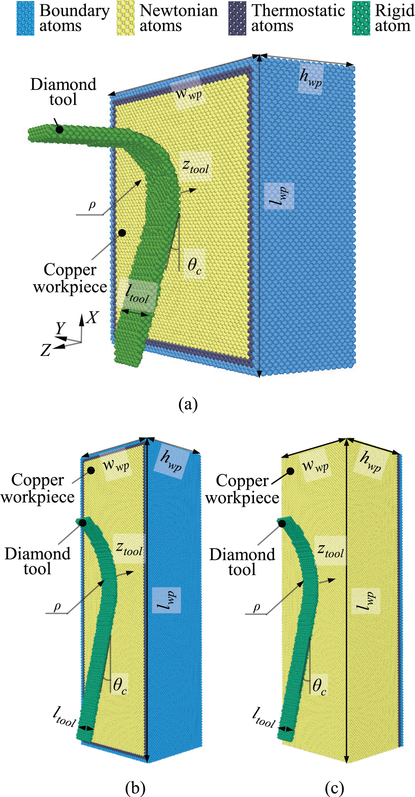
MD simulation models of tool–workpiece contact: (a) Model 1, (b) Model 2 and (c) Model 3.
Model 1, as shown in Figure 1, is for verifying the effectiveness of the proposed multi-relaxation time method to stabilize the MD model over a wide temperature range up to the room temperature under which practical microcutting and on-machine surface form metrology are conducted. The workpiece is surrounded by three layers of atoms, which are the boundary atoms, the thermostat atoms and the Newtonian atoms. Fixed boundary conditions (FBCs) are imposed in the outer surfaces of the three layers of the workpiece atoms except for the free (001) surface at z = 0. The position of the tool tip along the Z-direction is denoted as ztool. Taking into consideration that the purpose of Model 1 is for verifying the effectiveness of the proposed multi-relaxation time method, the sharpness ρ of the diamond tool, which is not related to this purpose, is set to be a small value of 3 nm for shortening the computation time. The rake angle θr and the clearance angle θc are set to be 0° and 7°, respectively, which are the typical values for practical diamond cutting tools.
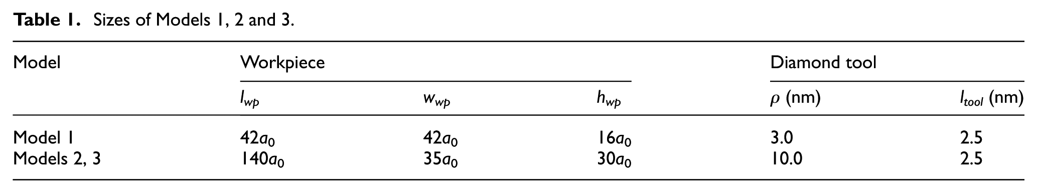
Models 2 and 3, as shown in Figure 1(b) and (c), respectively, are optimized from Model 1 for investigating the optimal boundary condition and model dimension, without increasing much the workpiece volume from Model 1, for reliable and cost-effective simulations of the elastic–plastic transition contact depth. The sharpness of the diamond tool in Models 2 and 3 is set to be larger than 10 nm as those of practical diamond tools. The widths of the workpieces along the Y-direction in Models 2 and 3 are shortened according to the Y-directional length of the modeled diamond tool to reduce the computational cost of the MD simulation. As shown in Figure 1(b), the boundary condition of Mode 2, which is based on the FBCs, is set to be the same as that of Model 1. As shown in Figure 1(c), periodic boundary conditions (PBCs), which can be imposed in the workpiece to simulate an infinite boundary plane,27,28 are set to the X- and Y- directions for Model 3. Therefore, the influence of the boundary condition on the evaluation of the elastic–plastic transition contact depth can thus be investigated by comparing the simulation results between Model 2 and Model 3. In addition, based on Model 3, in which the model size is changeable, the optimized model size conditions for evaluating the elastic–plastic transition contact depth can thus be investigated. For the sake of clarity, the sizes of the MD simulation Models 1, 2 and 3 are listed in Table 1. The workpiece volumes of the models are determined based on Cui et al., 29 which are regarded to be sufficient for reliable simulations.
Sizes of Models 1, 2 and 3.
For all the above models, heat dissipations in the MD simulations are carried out by maintaining the thermostat atoms at a constant simulation temperature through employing the Nosé–Hoover thermostat method. 30 The velocity-Verlet algorithm with a time step of 1 fs is used for integrating the Newton’s equations of motion for the thermostat atoms and the Newtonian atoms. 31
Figure 2 shows a schematic diagram of the simulation steps for the tool–workpiece contact. Before bringing the diamond tool to make into contact with the workpiece surface, the MD simulation model is first relaxed in a canonical ensemble. The canonical ensemble is a collection of all systems whose thermodynamic state is characterized by a fixed number of atom N, a fixed volume V and a fixed temperature T. 32 During the relaxation, the diamond tool tip is initially located at a Z-directional position of ztool_ini and kept stationary. As shown in Figure 2, the subsequent tool–workpiece contact is conducted by four consecutive stages, namely, the approaching, contacting, retracting and pulling-back stages. The tool is moved to make into contact with the workpiece surface at a command contact depth denoted as ztool_M and then retracted back to the initial position ztool_ini. All the approaching, contacting, retracting and pulling-back stages have a constant velocity that is set to be 20 m/s.
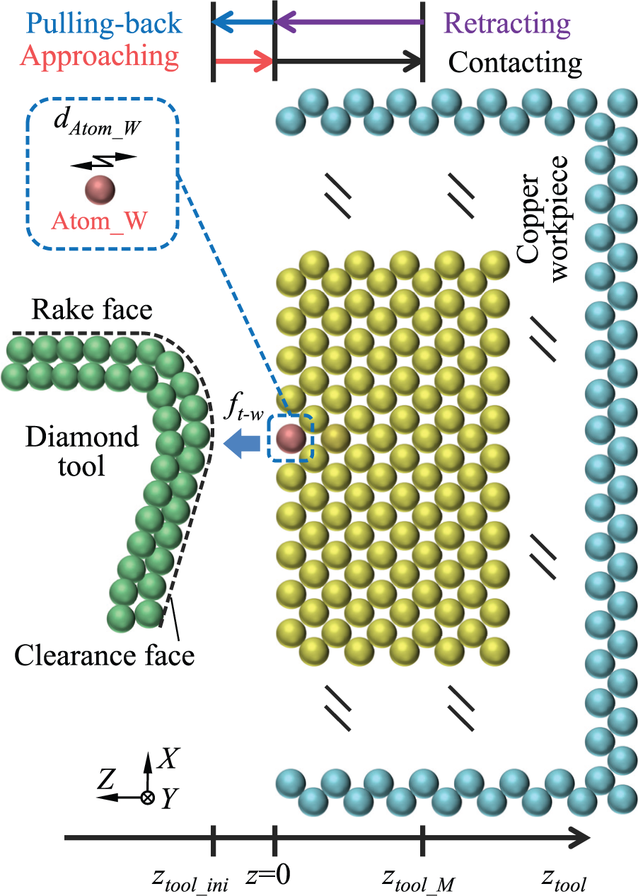
Schematic diagram of the simulation steps for the tool–workpiece contact.
The multi-relaxation time method has been proposed in our previous research for stabilization of the MD model based on the fact that the dominant temperature-induced vibration component of the workpiece atoms has a certain period determined by the size of the MD model. 23 The multi-relaxation time method is operated by averaging a group of simulation results, in which each of the simulations has the same tool–workpiece contact step but a relaxation step with a different relaxation time. With the averaging effect of the multi-relaxation time method, the periodic component of the atom vibration can thus be removed. This method has been proven to be effective for stabilization of the MD model at a low temperature of 0.1 K 23 where the amplitudes of the atom vibrations are relatively small. However, in real situation, the FS-FTS-based microcutting and on-machine surface form measurement are carried out at a room temperature around 293 K with much larger amplitudes of atom vibrations. In order to make the simulation results more practically useful, the effectiveness of the multi-relaxation time method for stabilization of the MD model is verified under the condition of room temperature.
An atom denoted as Atom_W, which is located at the center of the top surface of the workpiece, as shown in Figure 2, is employed as the target for investigating the temperature-induced atom vibrations. The vibration amplitude of Atom_W is defined as dAtom_W. The diamond tool is initially positioned at ztool_ini, which is set to be 0.3 nm above the top surface of the workpiece where z = 0. Figure 3(a) shows the simulation results of the vibrations of Atom_W with respect to the temperatures of 0.1 and 293 K, respectively. It can be seen from the figure that although dAtom_W increases with the increase in the temperature, the periods of the atom vibrations, which are only determined by the size of the MD model, are kept to be the same at the temperatures of 0.1 and 293 K. Figure 3(b) shows the evaluated dAtom_W under different temperatures. dAtom_W are evaluated to be 0.034, 0.067, 0.093 and 0.12 nm, respectively.
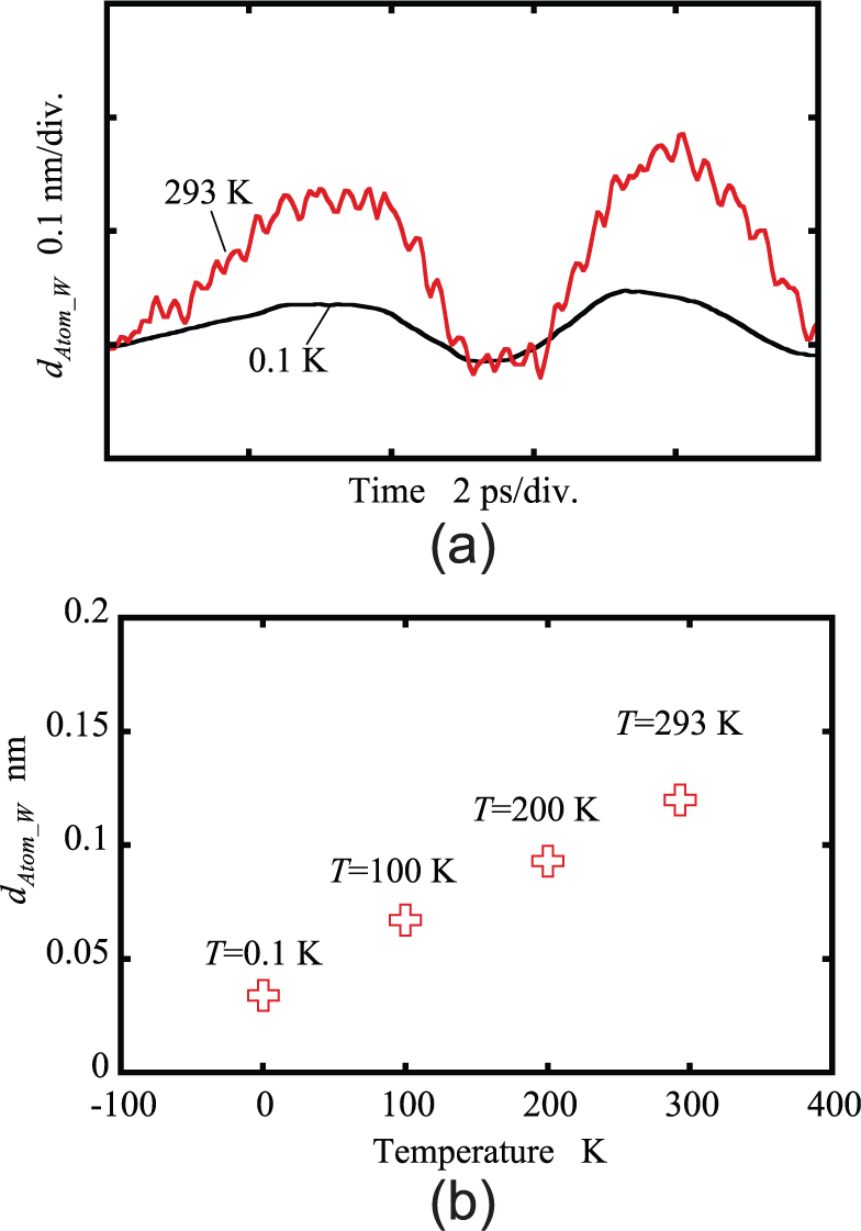
Effect of the temperature on the vibration of workpiece atom: (a) vibrations of Atom_W with respect to the temperatures of 0.1 and 293 K and (b) dAtom_W under different temperatures.
The proposed multi-relaxation time method is thus employed to deal with the simulation results at the temperatures of 0.1 and 293 K, respectively. Figure 4(a) and (b) shows the ft-w–ztool curves during the approaching and contacting stages of the tool–workpiece contact under simulation temperatures of 0.1 and 293 K, respectively. The horizontal axis represents the tool position and the vertical axis represents the total interatomic force applied on the tool. It can be seen from Figure 4(a) and (b) that both the simulation results at 0.1 and 293 K have a periodical component existing in the unstable ft-w–ztool curve, especially when the diamond tool is located at a position in the range from ztool = −0.15 nm to ztool = 0 nm. The stabilized ft−w–ztool curves by the proposed multi-relaxation time method are also plotted in the figure. It can be seen that the periodic vibration components can be well eliminated not only at the temperature of 0.1 K but also at the temperature of 293 K based on the multi-relaxation time method. This verifies that the multi-relaxation time method is effective for stabilization of the MD model under the condition of room temperature, which is employed for all the following simulations.
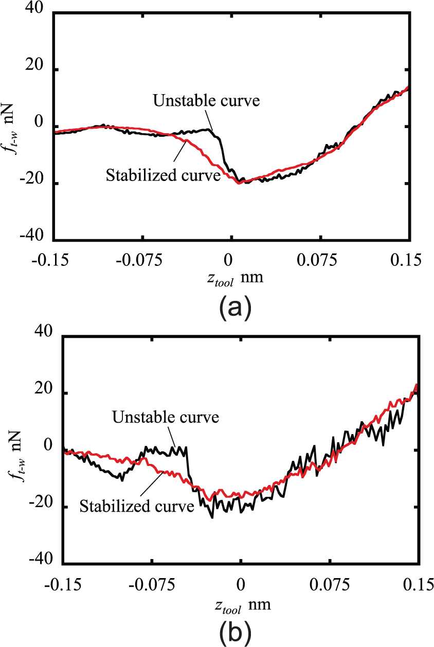
Effectiveness of the multi-relaxation time method: (a) T = 0.1 K and (b) T = 293 K.
By utilizing the multi-relaxation time method, the influence of the temperature on the elastic–plastic transition contact depth is also investigated by observing the surface defect after the tool–workpiece contact based on the accurate estimation approach proposed in the previous article. 23 Figure 5 summarizes the evaluated elastic–plastic transition depths of the workpiece surface at different temperatures. As shown in the figure, ztool_transition_final decreases from 0.34 to 0.28 nm when the simulation temperature is increased from 0.1 to 293 K. The results indicate that the plastic deformation of the workpiece becomes easier when the temperature gets higher. This phenomenon is well agreed with both the theoretical studies33–35 and experimental results. 36
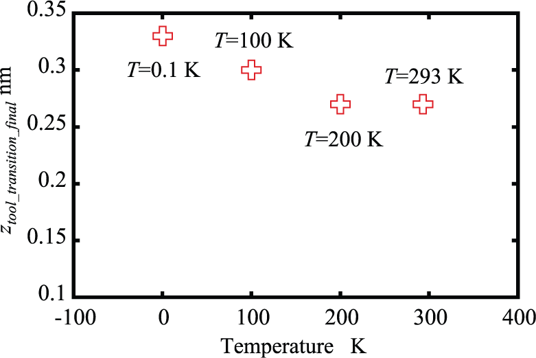
ztool_transition_final at different temperatures.
Characterization of the tool–workpiece contact under practical cutting edge sharpness by an optimized MD model
The simulations are then extended to characterize the tool–workpiece contact under different conditions including the boundary conditions, tool sharpness and workpiece model sizes based on Models 2 and 3, so that the optimized condition for evaluation of the elastic–plastic transition contact depth under a practical cutting edge sharpness of up to 30 nm can be determined.
Figure 6 shows the simulation results of the vibrations of Atom_W based on Model 2 which utilizes the FBCs and Model 3 which utilizes the PBCs. As can be seen in the figure, not only the amplitude but also the period of the workpiece atom vibration are influenced by the set boundary condition of the workpiece. The atom vibration amplitude increases from 0.15 nm for Model 2 to 0.20 nm for Model 3, and the atom vibration period increases from 8.0 ps for Model 2 to 11.0 ps for Model 3. The multi-relaxation time method is employed to stabilize the two models according to the vibration periods, respectively. Based on the stabilized Models 2 and 3, the elastic–plastic transition contact depths ztool_transition_final are evaluated and shown in Figure 7. ztool_transition_final are evaluated to be 0.22 nm for Model 2 and 0.23 nm for Model 3. The difference between them is only 0.01 nm. The results show that different boundary conditions of the workpiece do not significantly affect the simulation result in the elastic region of the workpiece. This agrees with the conclusion verified by Nair et al. 37 Although the boundary condition has little influence on the elastic–plastic transition contact depth, Mode 3 based on the PBCs, which is better in simulating a large or even an infinite size model that can be more close to the real situation, is chosen for all the following simulations.
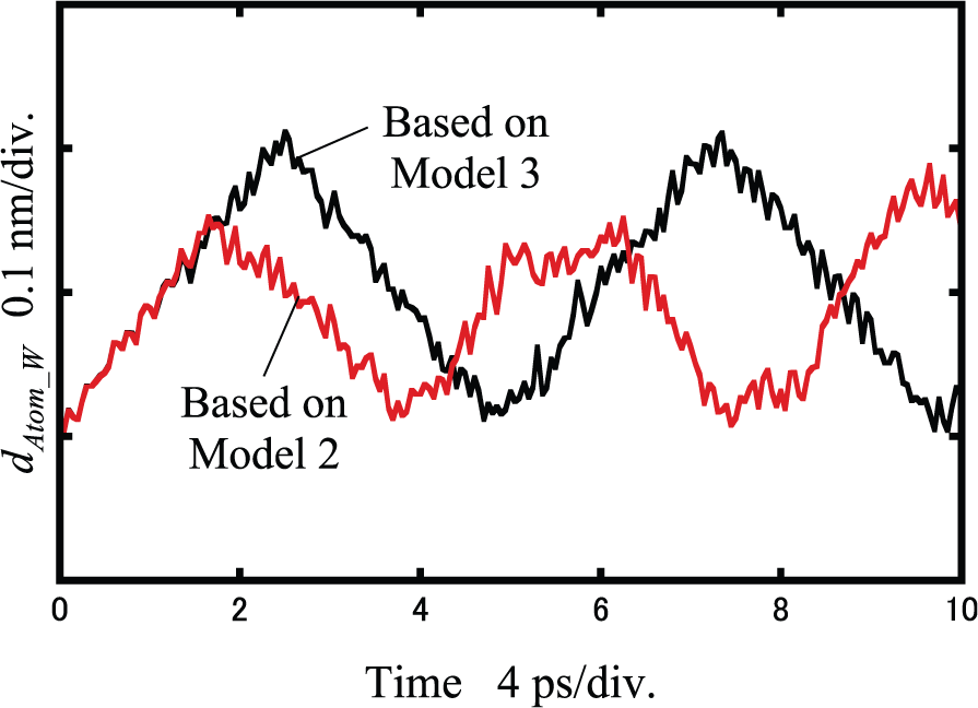
Effect of the boundary condition on the vibration of workpiece atom.
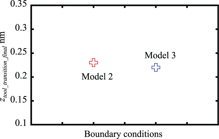
ztool_transition_final at different boundary conditions.
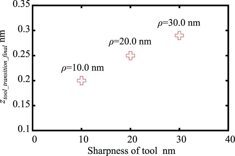
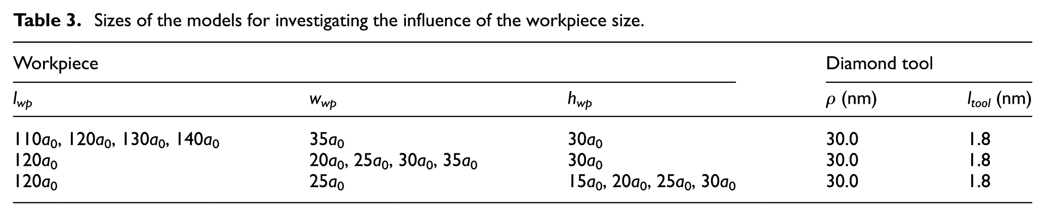
The influence of sharpness of the diamond tool cutting edge, which is one of the most critical parameters determining the surface quality of the fabricated workpiece, is also investigated. Differing from the previous research in which the diamond tool sharpness is set to be only below 5 nm 23 which is far from that of a real diamond tool, in this simulation, the sharpness of the diamond tool is set to be 10, 20 and 30 nm, respectively, so that the condition can be close to that of an actual diamond tool. The parameters of the model for investigating the influence of the tool sharpness are listed in Table 2, where a0 = 0.361 nm is the lattice constant of the copper. Figure 8 shows the evaluated ztool_transition_final with respect to the sharpness of the diamond tool. It can be seen that ztool_transition_final increases from 0.20 and 0.25 nm to 0.29 nm with an increase in the edge sharpness from 10 and 20 nm to 30 nm. The influence of the contact arc length of the diamond tool is then investigated. The contact arc length ltool of the diamond tool in the Y-direction, which is assumed to be a straight line as shown in Figure 1(c), is set to be 0.4, 1.1, 1.8 and 2.5 nm, respectively. The parameters of the size of the simulation model are listed in Table 2. The dependence of ztool_transition_final on ltool is shown in Figure 9. ztool_transition_final is evaluated to be 0.12, 0.26, 0.28 and 0.29 nm with respect to the set contact arc length of 0.4, 1.1, 1.8 and 2.5 nm, respectively. It can be seen that ztool_transition_final at the contact arc length of 0.4 nm is much smaller than that with a contact arc length larger than 1.1 nm. This is considered to be caused by the stress concentration when the contact arc length is too small. With the increase in the contact arc length, the effect of the stress concentration disappears so that the evaluated values of ztool_transition_final are close to each other. For a comprehensive consideration for avoiding the phenomenon of the stress concentration as well as reducing the computational time of the simulation at the same time, a contact arc length of 1.8 nm is set for the following simulation.
Sizes of the models for investigating the influence of the tool size.
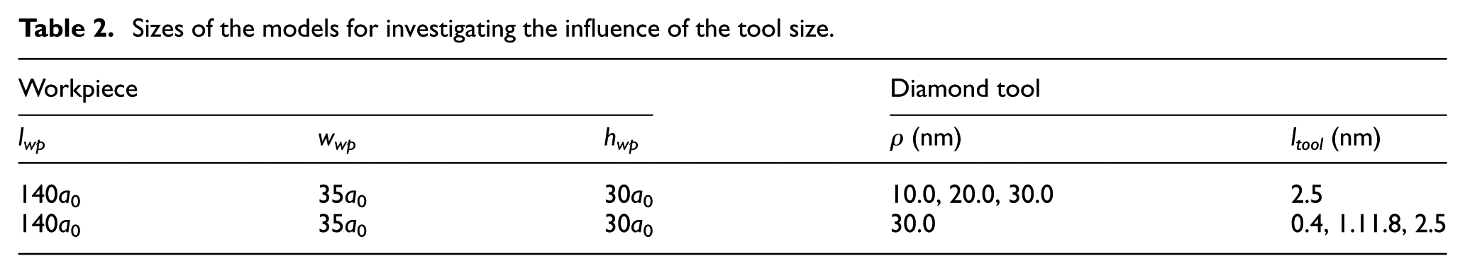
ztool_transition_final at different sharpness of the tool.
ztool_transition_final at different contact arc lengths of the tool.
It should be note that in real situation, a single-point diamond tool for microcutting is normally with a nose radius ranging from several tens of micrometers to several millimeters. 38 For a diamond tool with a nose radius of 2.0 mm, the contact arc length is approximately 2.3 µm for a command contact depth of 0.34 nm. 23 Taking into consideration the scale limitation of the general MD simulation, it is difficult to construct a tool model with a contact arc length on the order of several micrometers. For calculation of the contact force corresponding to a real contact arc length, it is necessary to expand the force value from MD simulated result according to the geometrical model.
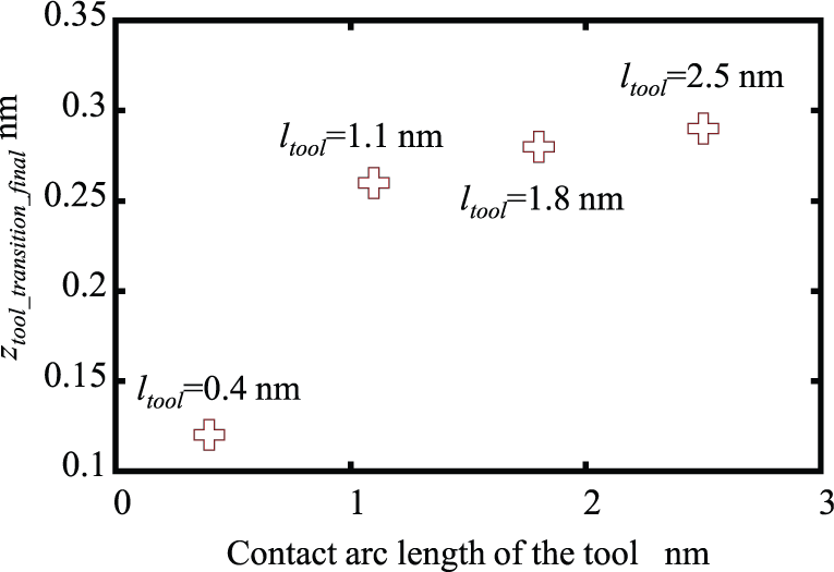
Based on the determined tool model, the setting range of the workpiece model is accordingly decided for the investigation of the influence of the workpiece model size on ztool_transition_final. Table 3 summarizes the parameters for investigating the influences of the length, width and height of the workpiece. First, the influence of the length of the workpiece model lwp on ztool_transition_final is investigated. The width wwp is fixed to be 35a0, the height hwp is fixed to be 30a0 and the length of the workpiece model lwp is varied from 110a0 to 140a0 with an increase step of 10a0 where a0 = 0.361 is the lattice constant of copper. Figure 10 shows the evaluated ztool_transition_final with respect to the varied lwp. As can be seen in the figure, ztool_transition_final is evaluated to be 0.27, 0.29, 0.30 and 0.29 nm corresponding to the set lwp of 110a0, 120a0, 130a0 and 140a0, respectively. Since the set length lwp is much larger than that of the contact area between the diamond tool and the workpiece surface, the influence of lwp on ztool_transition_final is insignificant. Taking into consideration when lwp is equal or larger than 120a0, the influence of lwp on ztool_transition_final is insignificant, and lwp is set to be 120a0 in the following simulations.
Sizes of the models for investigating the influence of the workpiece size.
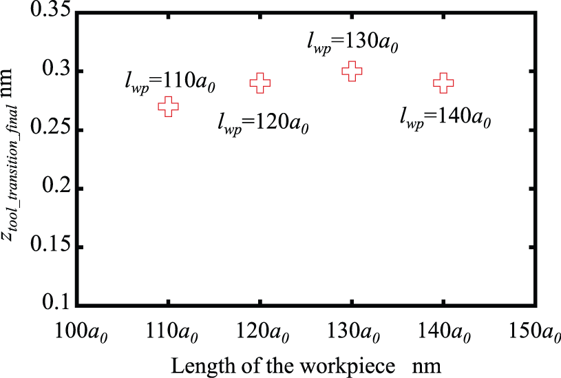
ztool_transition_final at different lengths of the workpiece.
Similarly, the influence of the width of the workpiece model wwp on ztool_transition_final is investigated. The width of the workpiece model wwp is increased from 20a0 to 35a0 with a step of 5a0. Figure 11 shows the evaluated ztool_transition_final with respect to the varied wwp. ztool_transition_final is evaluated to be 0.31, 0.29, 0.28 and 0.29 nm corresponding to the set wwp of 20a0, 25a0, 30a0 and 35a0, respectively. Similar to lwp, since the set width wwp is much larger than that of the contact area between the diamond tool and the workpiece surface, the influence of wwp on ztool_transition_final is also insignificant. wwp is set to be 25a0 for the following simulation.
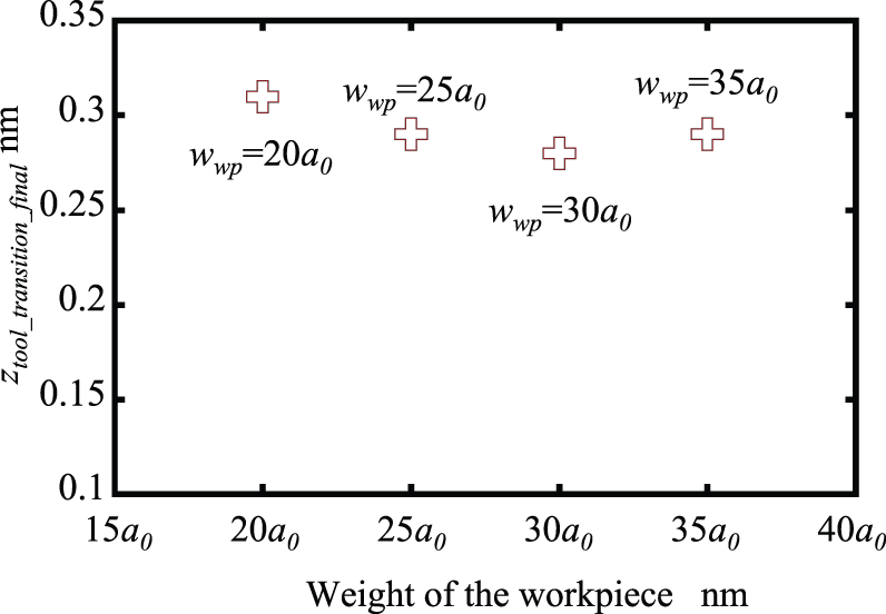
ztool_transition_final at different widths of the workpiece.
By fixing lwp to be 120a0 and wwp to be 25a0, the influence of the height hwp of the workpiece model on ztool_transition_final is investigated. Figure 12 shows the evaluated result. ztool_transition_final is calculated to be 0.27, 0.29, 0.30 and 0.29 nm corresponding to hwp of 15a0, 20a0, 25a0 and 25a0, respectively. It can be seen from the figure that ztool_transition_final becomes independent on the height of the workpiece when hwp increases to 20a0. This indicates that when the height of the workpiece is larger than a certain value, the effect of the workpiece size on the elastic–plastic transition contact depth also becomes insignificant.
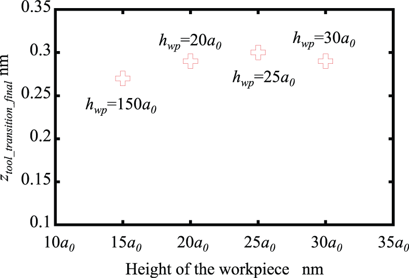
ztool_transition_final at different heights of the workpiece.
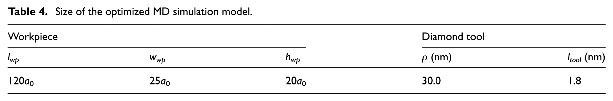
Based on the above analysis, an optimized MD simulation model is constructed for evaluation of ztool_transition_final with practical considerations. Table 4 summarizes the parameters of the optimized simulation model. In the optimized model, the size of the workpiece is set to be 120a0 (lwp) × 25a0 (wwp) × 20a0 (hwp). The sharpness of the diamond tool is 30 nm. The simulation temperature is 293 K. Figure 13(a) shows the atom position after the pulling-back stage with a command contact depth of 0.31 nm. Since there is no surface defect observed, ztool_M of 0.31 nm is considered to be smaller than ztool_transition_final. When ztool_M increases to be 0.32 nm, as shown in Figure 13(b), some defects can be observed on the workpiece surface. Therefore, the elastic–plastic transition contact depth ztool_transition_final is evaluated to be 0.32 nm under such a specified practical condition for microcutting and on-machine surface form metrology based on the FS-FTS. The corresponding contact force is evaluated to be 134 nN.
Size of the optimized MD simulation model.
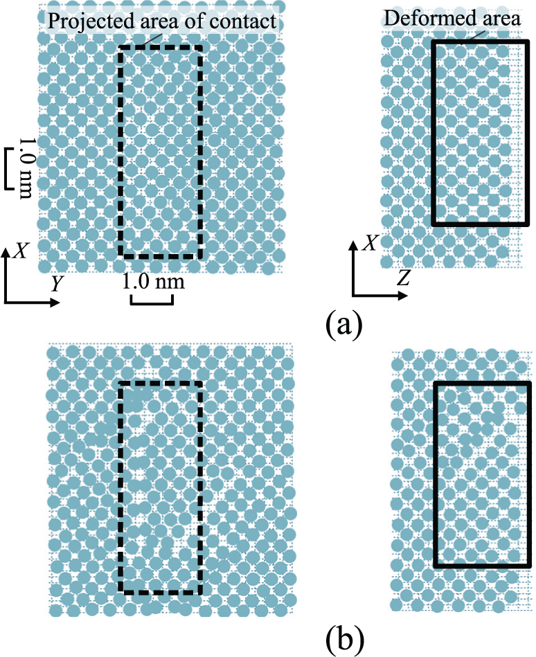
Atom positions of the workpiece in the optimized model under various command contact depths: (a) ztool_M = 0.27 nm and (b) ztool_M = 0.28 nm.
Conclusion
MD simulations have been carried out to characterize the subnanometric elastic–plastic transition of tool–workpiece contact for on-machine surface form metrology based on an FS-FTS. The stabilization of the MD model at room temperature, under which the FS-FTS-based microcutting and on-machine measurement are conducted, has been successfully achieved using the multi-relaxation time method. This has made it possible to accurately characterize the subnanometric elastic–plastic transition of tool–workpiece contact without the influence of the temperature-induced atom vibrations. In addition, comprehensive investigations of the influences of tool edge sharpness, boundary condition and size of the workpiece model have been carried out to search for an optimal MD model for making reliable and cost-effective simulations for evaluation of the elastic–plastic transition contact depth. Based on the optimized model in which the simulation conditions are set to be close to the real situation of microcutting and surface form metrology based on the FS-FTS, the elastic–plastic transition contact depth is evaluated to be 0.32 nm when a single-point diamond tool with a practical edge sharpness of 30 nm is employed to make into contact with a copper workpiece surface at a room temperature set to be 293 K.
The evaluation of the simulation uncertainty and simulation of the scanning process for the on-machine surface metrology will be carried out. Comparing the MD simulation with the experimental results is also planned as future work.
Footnotes
Declaration of conflicting interests
The author(s) declared no potential conflicts of interest with respect to the research, authorship and/or publication of this article.
Funding
The author(s) disclosed receipt of the following financial support for the research, authorship, and/or publication of this article: This project was supported by Japan Society for the Promotion of Science (JSPS).