
Abstract
Fast tool servo technology plays important roles in manufacturing complex free-form surfaces for the modern optics industry. However, its stroke length is restricted to few tenths of microns due to the limited expansion of piezoelectric actuator. A long-stroke fast tool servo may be one of the possible ways to increase the stroke length for fulfilling the surface height requirement. This article proposes a novel approach to increase the stroke length. This article describes a novel fast tool servo diamond turning method with layered tool trajectories to extend the limited stroke length without modifying an existing fast tool servo system. The proposed method has successfully extended the effective fast tool servo stroke length to about fivefold of its maximum possible stroke length.
Keywords
Introduction
Ultra-precision diamond machining allows the micromechanical fabrication of microstructured surfaces with profiling depths of several tens of micrometres. Over the past several decades, the ultra-precision diamond machining techniques have been evolved and are capable of performing the machining of free-form microstructured surfaces. The four common diamond-machining techniques to machine these free-form surfaces on ultra-precision machines are the slow slide servo (STS), the fast tool servo (FTS), raster machining and micro-milling. These techniques have exhibited the capability of machining complex surfaces like lens arrays, polynomial free-form, biconics, aspheric cylinders and non-uniform rational B-spline (NURBS) defined free-form surfaces. A process chain as shown in Figure 1 describes the flow of fabrication methods of free-form surfaces from the design to metrology. 1 This process chain employs computer-aided manufacturing (CAM) software to generate tool trajectory and the compensation of surface form error to modify/correct the tool trajectory.
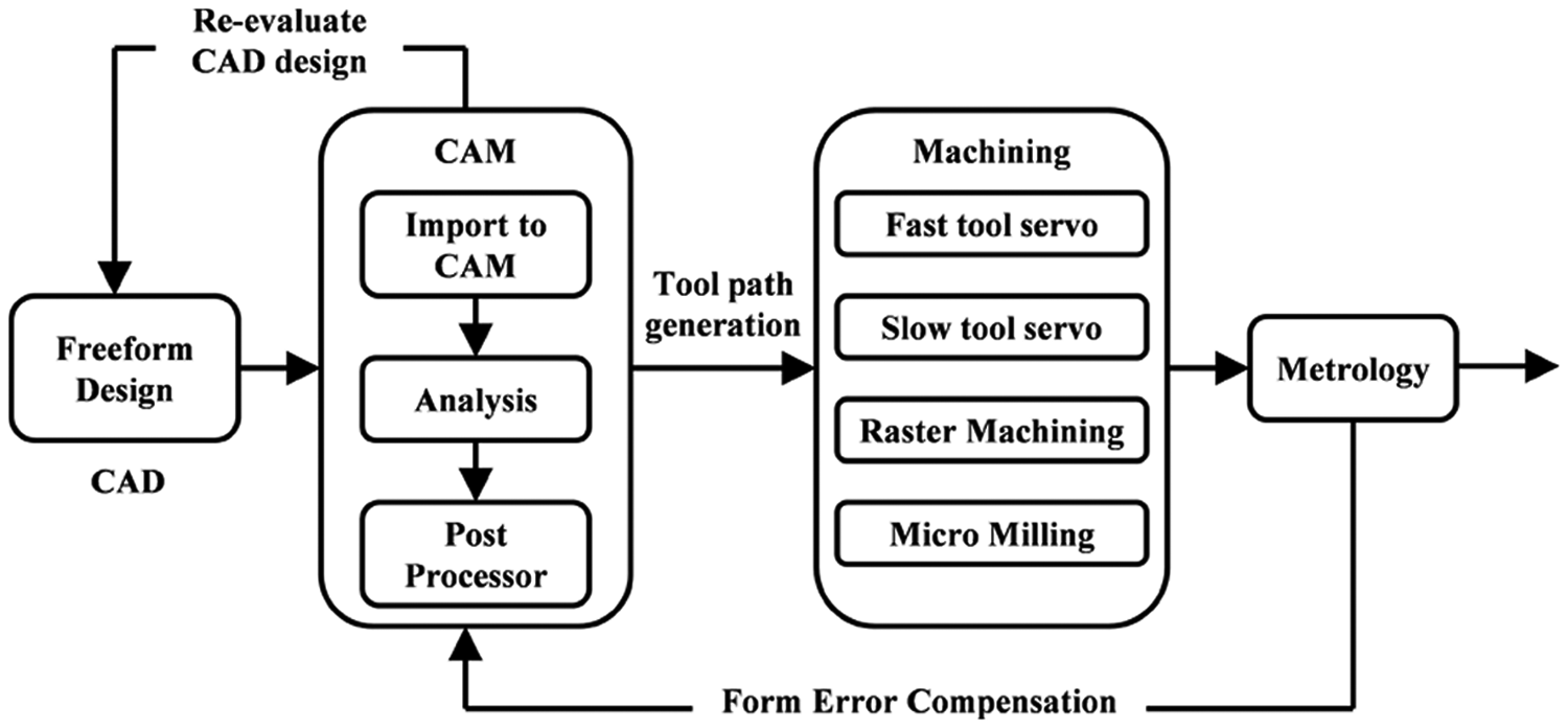
Process chain for the fabrication of free-form surfaces. 1
FTS diamond turning has been widely employed for fabricating the nonrotational symmetrical surfaces due to its high resolution and bandwidth.2,3 Although STS technique has a longer stroke length of up to several millimeters, its limited bandwidth restricts the speed of Z-axis (in the tool trajectory) for machining a complex free-form surface. When raster machining is employed, there are several shortcomings to overcome such as relatively long setup, difficult setup and restriction of tool swing diameter. Lastly, micro-milling method requires overcoming of inherent static and dynamic limitations in the ultra-precision machine system, and material removal rate is much lower than the turning process. Therefore, FTS diamond turning is often employed for machining free-form surfaces.
Long-stroke FTS
FTS technology plays important roles in manufacturing complex free-form surfaces for the modern optics industry. The increasing complexity of surfaces requires more components in shorter spatial wavelength and thus drives simultaneously the need for high bandwidth, high acceleration and high accuracy of the FTS. 4 However, its stroke length is restricted to few tenths of microns due to the limited expansion of piezoelectric actuator. 5 A long-stroke FTS may be employed to fulfill the profile height requirement that is greater than the FTS stroke length.4,6–10 Several research works4,6–11 studied the feasibility for the long stroke of FTS. Common methods to extend the stroke of FTS are by using rotary FTS 4 and designing flexure having a higher displacement amplification mechanism incorporated with voice coil and/or piezoelectric actuators.6,7 Ludwick et al. 4 developed a rotary FTS with a motor and bearings with peak accelerations of 500 m/s 2 . This rotary FTS is capable to machine a surface feature having amplitudes of up to 10 mm at 50 Hz. Although an adaptive feed-forward cancelation has been employed to eliminate a 50-Hz component of error motion, there is still a tool position error of 0.63 µm because the higher harmonic frequency error is not attenuated during cutting. Kim et al. 6 have developed a long-stroke FTS having a maximum stroke of 432 µm. It incorporates a piezoelectric actuator with a displacement amplification mechanism composed of several levers and hinges. Rakuff and Cuttino 7 have developed a long-stroke FTS with a voice coil actuator and a flexure hinge that has maximum accelerations of 260 m/s 2 and bandwidths of up to 140 Hz. The maximum displacement range of the cutting tool was 2 mm. Permanent magnet voice coil actuators are generally free of hysteresis with a nearly linear current versus force relationship for smaller strokes. This is an advantage over the commonly used piezoelectric actuators that require charge control to avoid hysteresis and creep. However, the flexure structure in this FTS has a low resonance frequency that can cause resonance and its low stiffness is liable to generate vibration in vertical direction. Both of these effects have an adverse impact on the quality of machined surface. Buescher et al.8,9 proposed a live-axis turning technique that utilized an air-bearing slider and linear motors to increase the stroke length up to 4 mm but relatively at a low bandwidth of 20 Hz. A hybrid method may also be employed to increase the stroke length of FTS.10–12
From the literature review, it can be concluded that long-stroke FTSs are usually actuated by piezoelectric and voice coil actuators. Piezoelectric FTSs are usually guided by flexure hinge structures that are more suitable for error compensation. However, piezoelectric FTSs often have a low resonance frequency because of the lever mechanism. The lever mechanisms also bring hysteresis and tracking error because of the lever bending. Voice coil FTSs have longer strokes but lower bandwidths than other FTSs. Hence, the stroke and the bandwidth are two separate performance parameters that cannot be optimized simultaneously for most cases. Although there are numerous works to increase the stroke length, it may take a lot of effort and long duration to modify an existing FTS system for the sake of fulfilling the surface height requirement.
This article reports a novel FTS diamond turning method with layered tool trajectories to overcome the limited stroke length without modifying an existing FTS system. To the authors’ best knowledge, there is no literature study on the diamond machining of microstructured surfaces whose heights are greater than the stroke length of FTS. Hence, this is the first work to study the layered tool path generation for FTS diamond turning of microstructured surfaces.
Layered tool trajectory
Conventional FTS diamond turning as shown in Figure 2 utilized three controlled axes, namely X-, C- and W-axes. X-axis is the radial movement that controls the feed toward the spindle center and is also perpendicular to the spindle axis (Z-axis). C-axis is the spindle rotational direction about the Z-axis. W-axis is the FTS stroke that controls the feed direction into the workpiece surface and is parallel to the Z-axis.
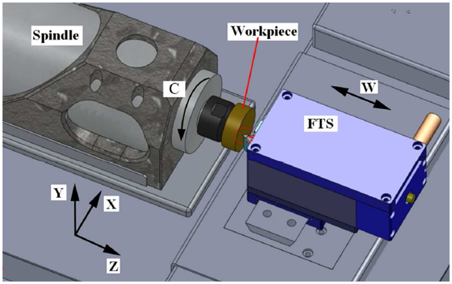
Schematic diagram of FTS turning.
The tool trajectory for FTS turning is commonly described as in Figure 3 and is represented by the polar coordinate system as
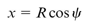
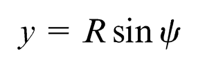
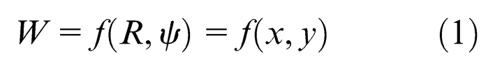
where R is the radial position of the X-axis (relative to the center of the machine spindle), ψ is the rotational angle of the machine spindle and W is the stroke of FTS for the tool trajectory with respect to a cutting point (x, y).
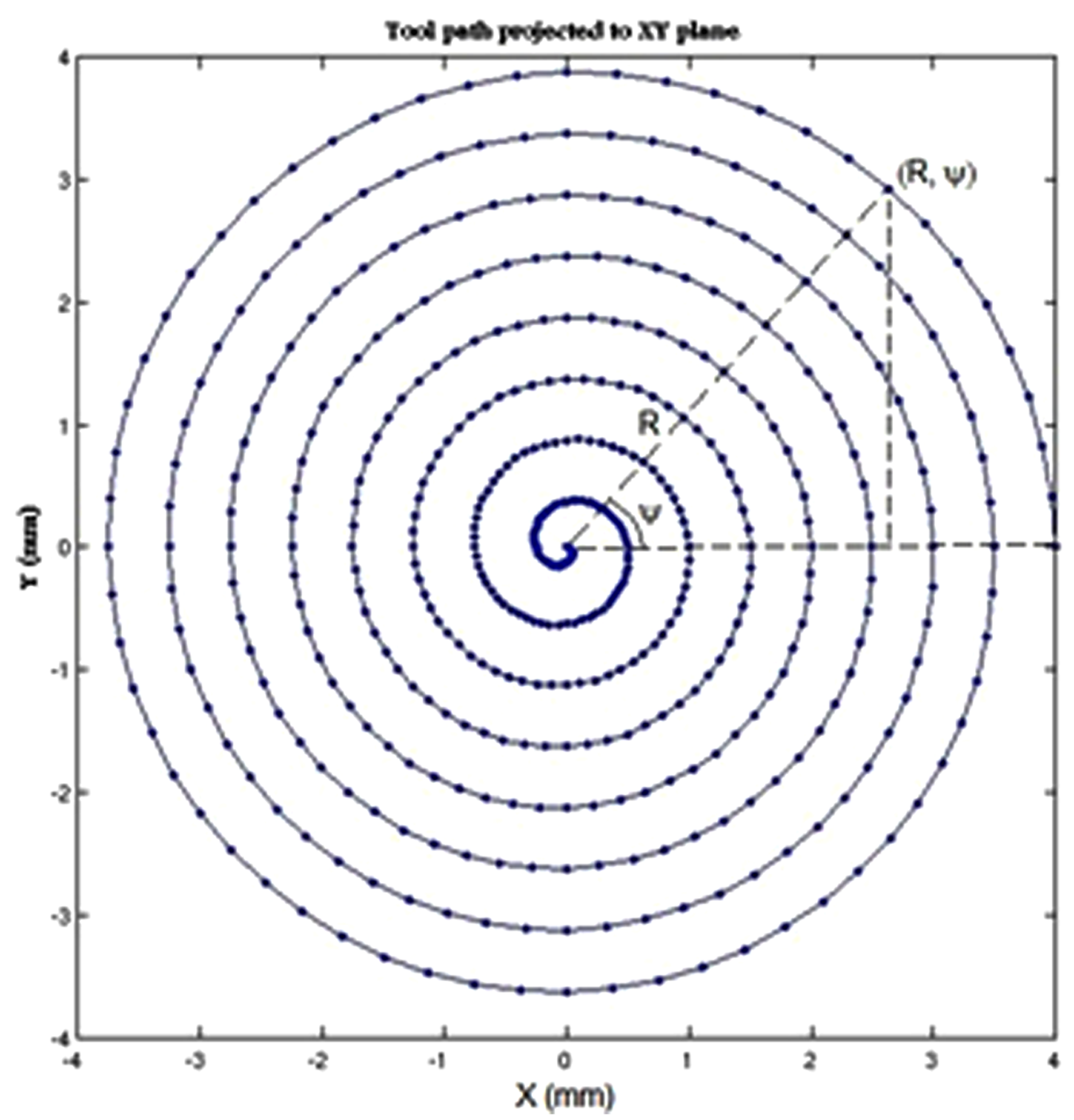
Tool path trajectory projected onto XY plane.
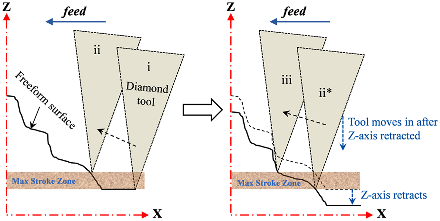
The proposed layered tool trajectory method incorporates an additional fourth working axis (Z-axis) as described in Figure 4. This fourth or Z-axis plays a critical role for extending the stroke length of FTS in this proposed method. During the FTS diamond turning, a stepper motor controller stops C-axis motion (spindle) at a position where the FTS tool reaches its upper limit of maximum stroke zone (ii). Then the Z-axis motor controller retracts the workpiece surface to the lower limit of maximum stroke zone of FTS Wmax. After the retraction of the workpiece surface (Z-axis), the FTS re-extends its tool to the lower limit of its stroke zone (ii*) and continues machining in the feed direction (iii). This cycle shall be repeated until the whole process completes the machining of the desired surface profile and FTS tool reaches the top of the surface profile. Therefore, the stroke of FTS for the tool trajectory in equation (1) can be rewritten as
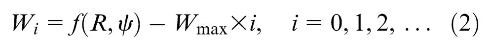
where Wmax is the maximum stroke length of FTS or the maximum stroke zone and i is the ith Z-axis retraction during layered tool trajectory. Figure 5 shows an illustration of layered tool trajectory that is projected onto the ZX plane. Figure 5(a) displays a series of Z-axis retraction in the tool trajectory whenever the FTS tool reaches the upper limit of FTSmax stroke zone. Hence, the original tool trajectory is being modified into the layered tool trajectory as shown in Figure 5(b).
Schematic diagram of layered tool trajectory.
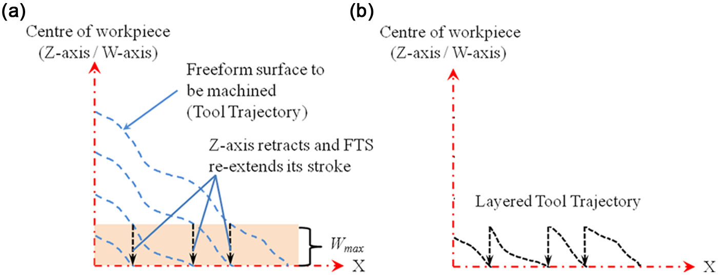
(a) Original tool trajectory and (b) layered tool trajectory.
Tool trajectory control
The common method for generating tool trajectory control points is by angle equal method, where these control points are generated at regular angular interval and the angular interval is described as
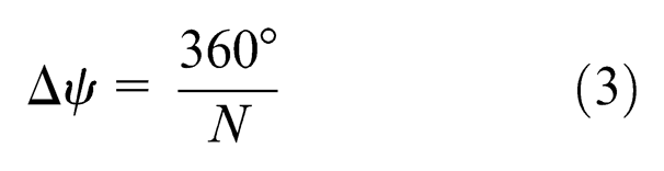
where N is the number of sampling points per revolution.
It is known that large sampling number gives a better surface form accuracy. However, the maximum frequency of generated tool trajectory must not be greater than the closed-loop bandwidth of FTS system. 13 Large sampling number also reduces the rotational spindle speed that may lead to difficulty in cutting several materials, especially ductile metals require high cutting speed. Hence, it is necessary to select appropriate sampling number for a good tool trajectory control. The effect of tool nose radius on machined surface quality cannot be ignored. Therefore, in order to achieve a correct surface profile, it is deemed necessary to consider the tool nose radius compensation for generating tool trajectory control points. If the tool trajectory is generated without the tool nose radius compensation, the surface profile would suffer the adverse effect of overcutting problem. 14 As shown in Figure 6, this overcut depth Ez is described as
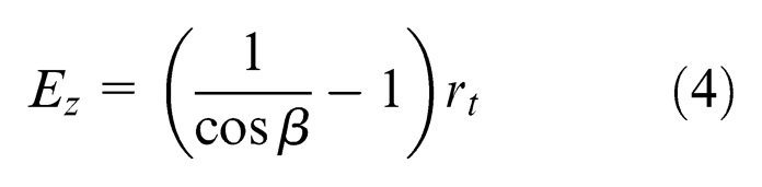
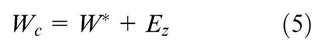
where β is the surface slope at the cutting point and rt is the tool nose radius of the diamond tool. The compensated FTS stroke length for the tool trajectory is
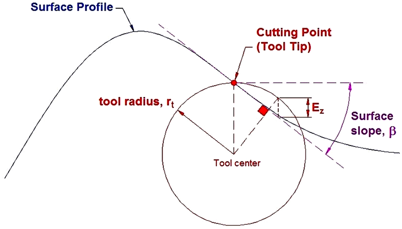
Tool trajectory along the surface profile with tool nose radius. 14
In this proposed layered tool trajectory method, there are two other considerations to take into account for a good tool trajectory control, namely, (a) the transition point Pi where the Z-axis controller retracts the workpiece and the FTS re-extends its tool and (b) the amount of Z-axis retraction. If this transition point is poorly assigned as illustrated in Figure 7, an overcutting problem would occur on the machined surface due to the dynamic response of the C-axis motion.
Exit and reentry points on the upper limit of FTS stroke zone.
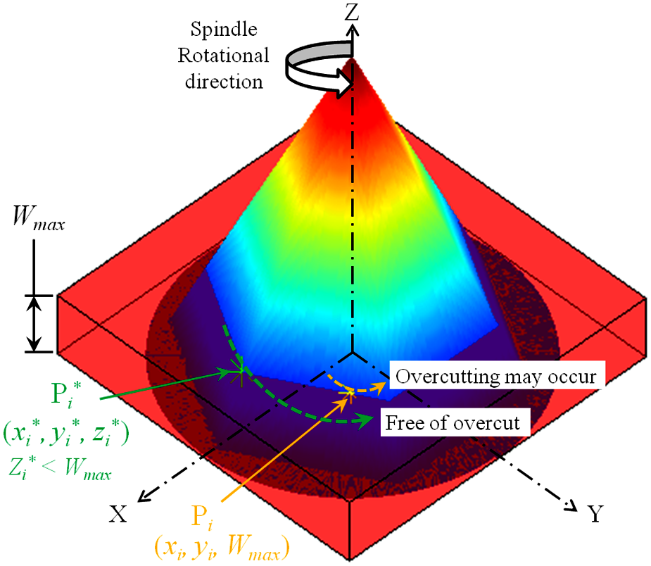
Thus, it is desired to avoid unnecessary overcuts in every layered tool trajectory by controlling all exit/reentry points of FTS tool to the outermost radii of surface outline within FTS stroke zone
Effect of Z-axis retraction, (a) over-retraction and (b) correct retraction.
The amount of Z-axis retraction Zri can be found by determining the maximum Z-axis boundary Zbmax within a circumscribed radius
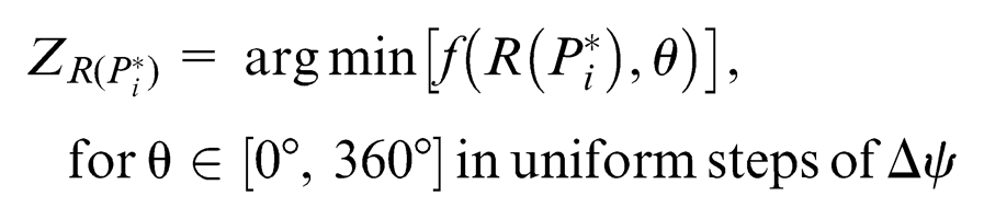
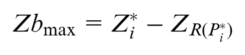
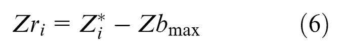
where
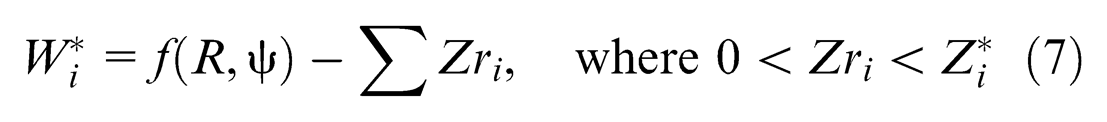
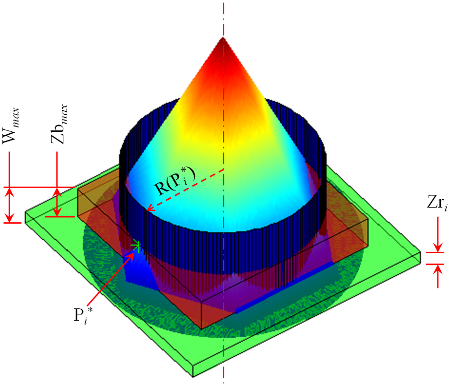
Schematic diagram for determining Z-retraction.
The process flow for generation of tool trajectory control points is shown in Figure 10.
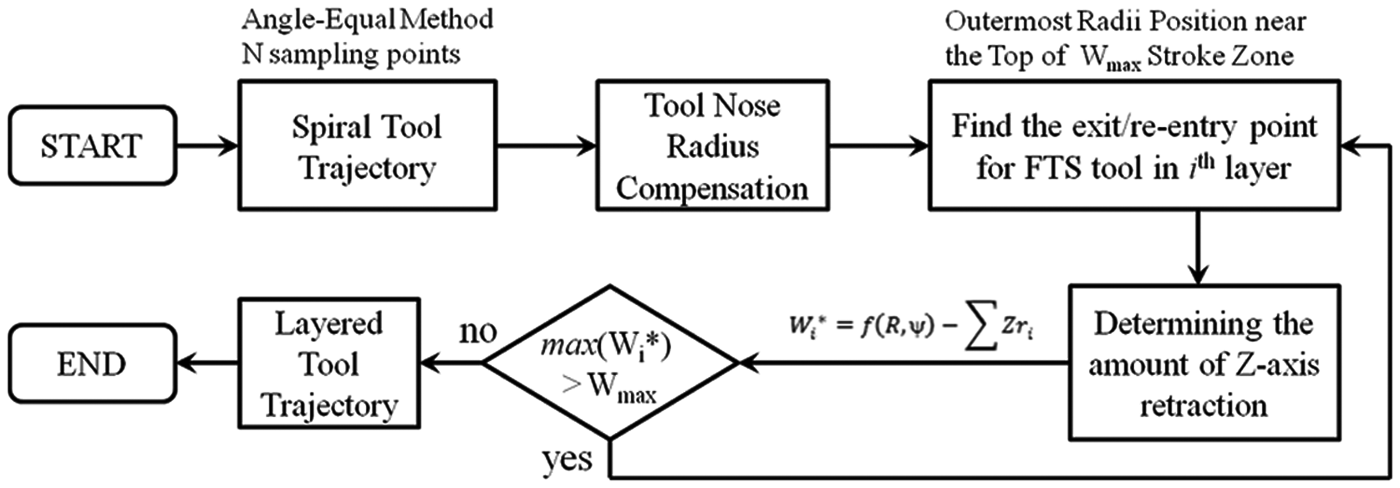
Process flow for generating layered tool trajectory.
Experiments and discussions
Several experiments were conducted to study the feasibility of the proposed layered tool trajectory method for the fabrication of a single microprism. The single microprism was fabricated with parameters shown in Table 1.
Fabrication parameters.
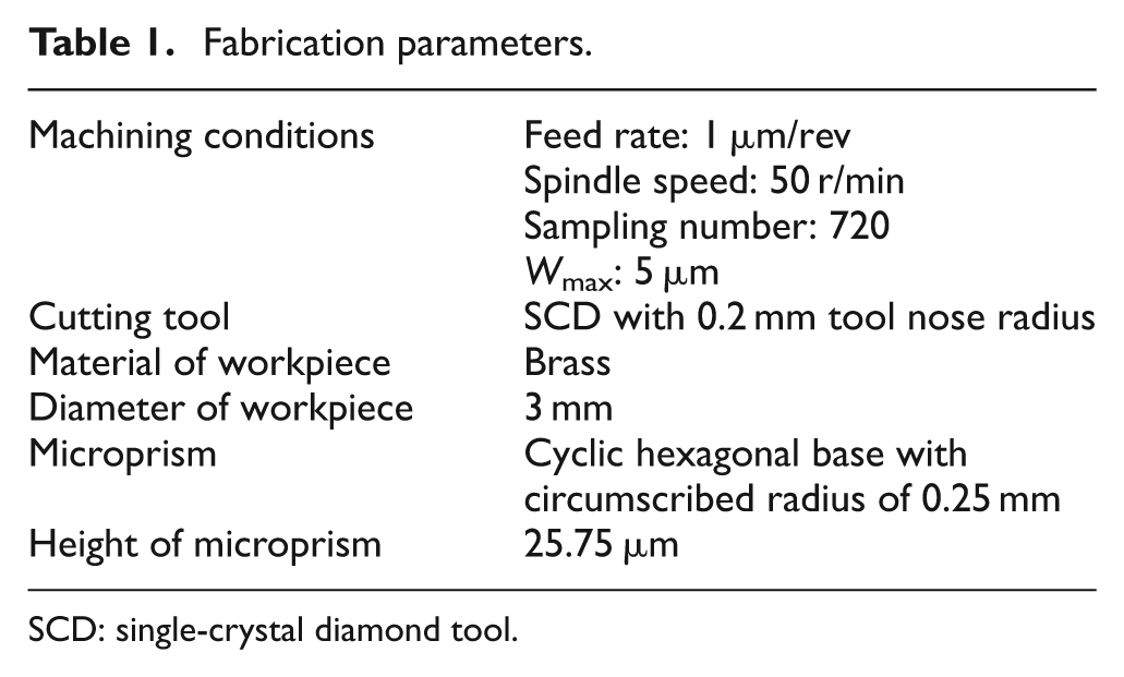
SCD: single-crystal diamond tool.
The cutting conditions were chosen with the aid of the simulation system based on the capability of the existing FTS and the programmable multi axis controller (PMAC) as shown in Figure 11. 15 Figure 11(a) shows that an incorporated controller configuration integrates the FTS into the diamond turning machine having a total of four axes (X-, Z-, W- and C-axes). In contrast to any conventional diamond-turning machine, the C-axis is controlled in closed-loop allowing the command of C-axis to move to any desired angular position. The programming for the fabrication of the microstructured surfaces is easier because it inherited the programming idea used in computer numerical control (CNC) machining. The movement of the FTS is time synchronized, and thus, the motion trajectory of the FTS is not fluctuating. A simulation system as shown in Figure 11(b) is being employed for proper movements of FTS. With the given desired microstructural surface and material, this simulation system chooses suitable FTS, cutting conditions and geometry of cutting tool, generates the tool path for the surface and produces NC program for fabrication.
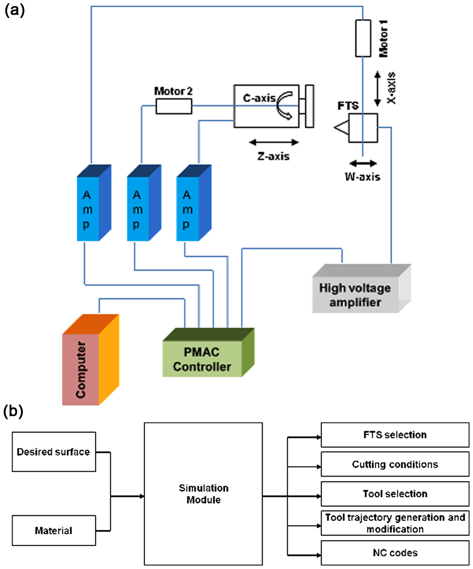
Schematic diagram for setups of diamond turning with FTS. 15 (a) Incorporated controller configuration and (b) simulation system.
A simulated layered tool trajectory for machining a microprism is shown in Figure 12. Figure 13 shows that the machined microprism appears to have a profile distortion caused by the tool center alignment error 16 of 10 microns in y-direction. The height and surface roughness of a microprism are measured using a white light interferometer.
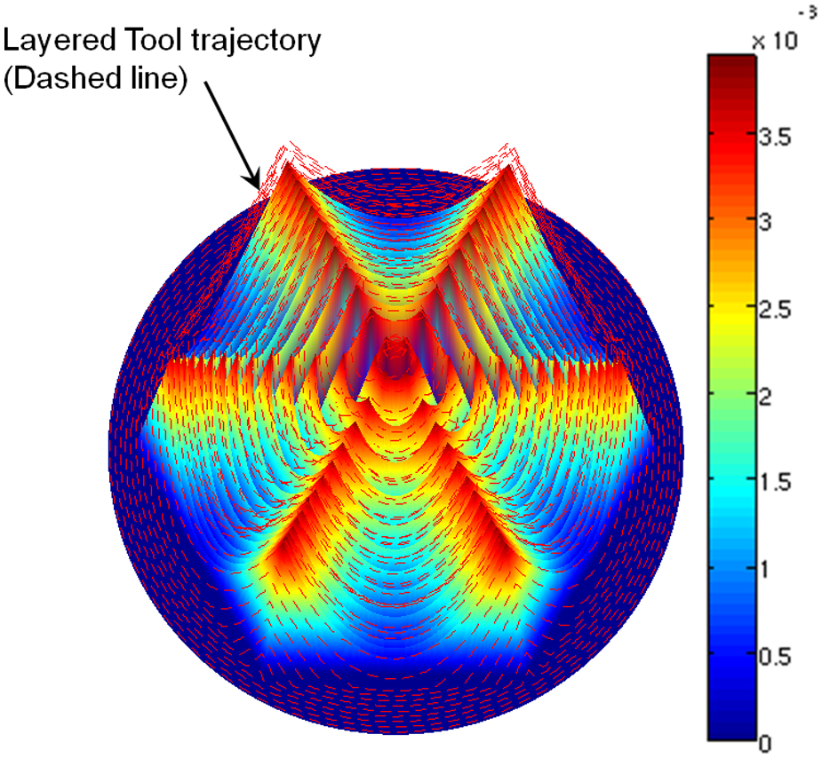
Simulated three-dimensional layered tool trajectory.
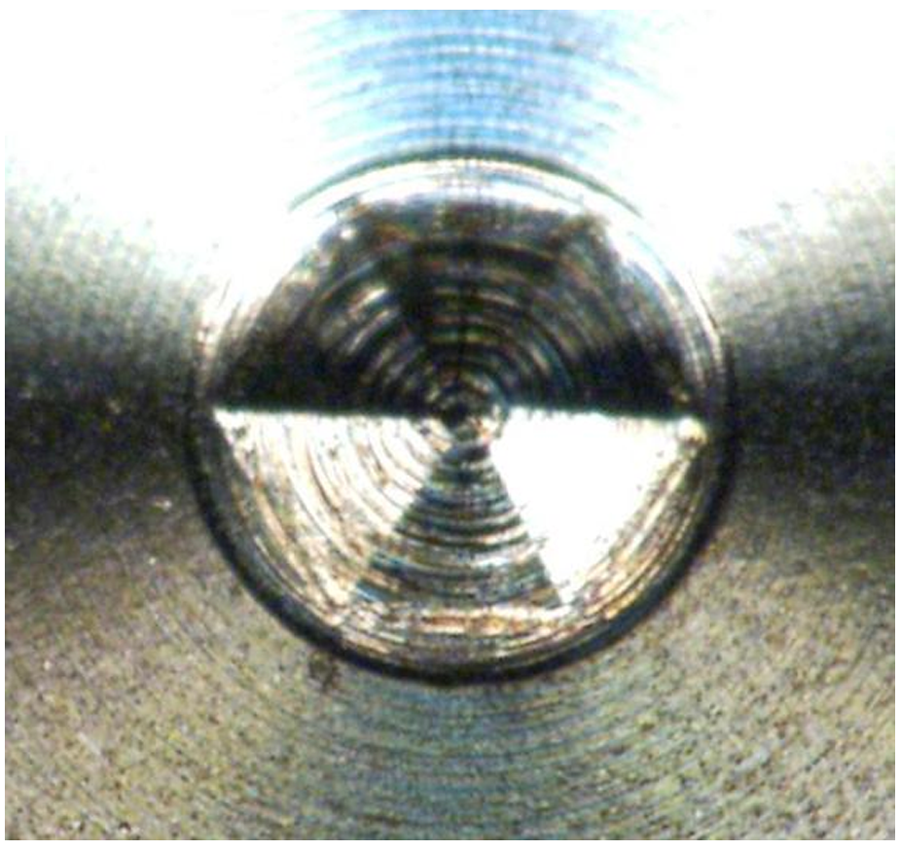
Machined microprism.
In this article, two different techniques of white light interferometry have been employed for the measurements of machined surface, namely phase shift interferometry (PSI) and white light vertical scanning (VSI). With the consideration for advantages and limitations, the proper selection of both the techniques is discussed in the study of Olszak et al.
17
Hence, VSI mode is employed for height measurement and PSI mode for surface roughness measurement. Importantly, the tilting of all specimens (surface preparation) obtaining good contrast fringes is deemed necessary for accurate measurements. Figure 14 shows that the measured value for the height of a microprism is 25.09 µm and an error of 0.66 µm (2.56%) as compared to the designed height of 25.75 µm. The error in the height is most likely caused by the dynamic response of Z-axis motion and repeatability of stepper motor (C-axis). The dynamic response leads to positioning error for each Z-axis retraction, causing
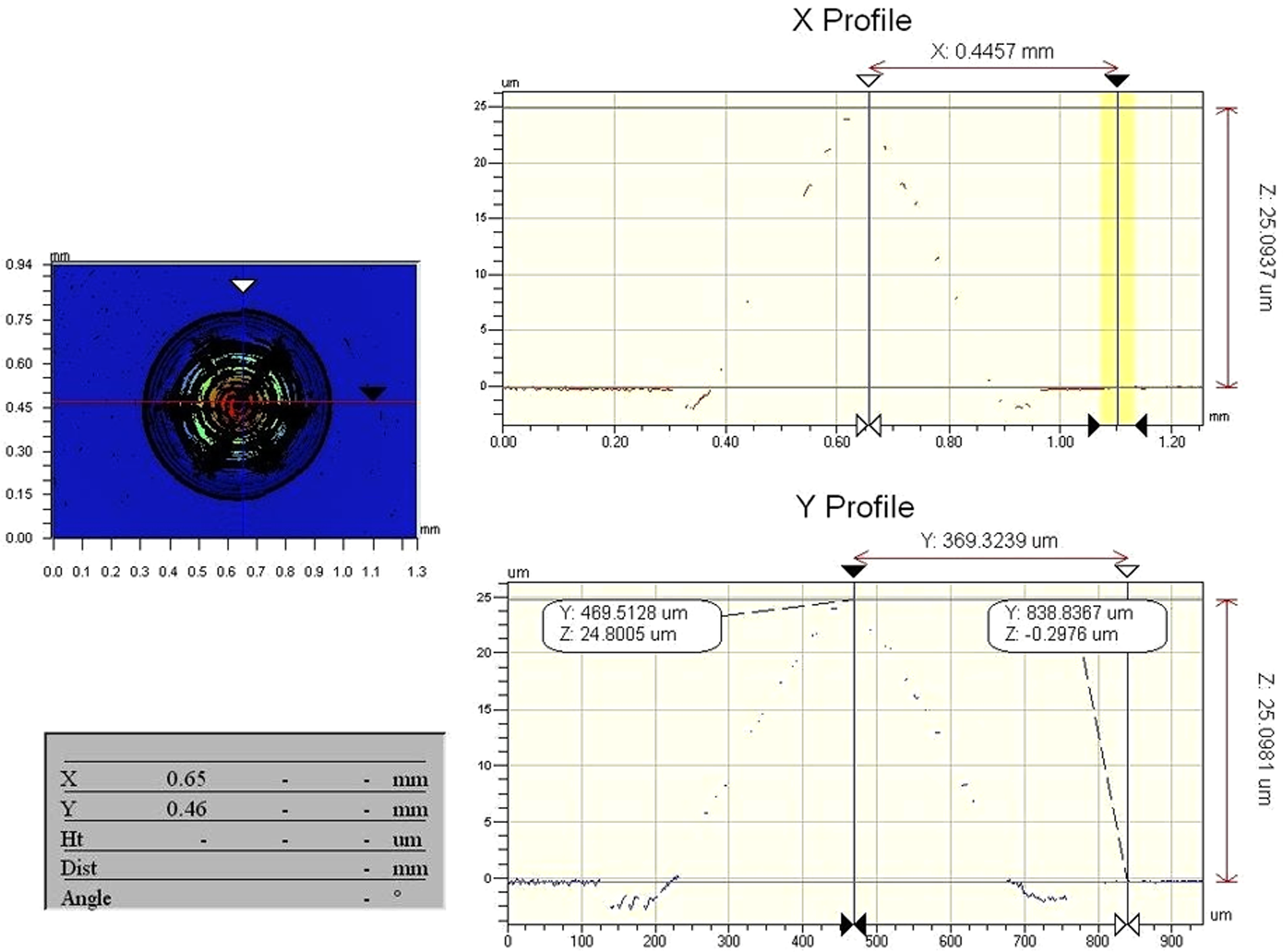
Overall height measurement of a fabricated microprism.
Figure 15 shows that an optical magnification of 10.21 was utilized for measuring surface roughness under a PSI mode giving a scanning area of 640 × 480 µm2, which was wide enough to cover a single face of a microprism. Only a single face of a microprism is selected for its surface roughness measurement since it is tedious to tilt every face of a microprism to measure surface roughness. Hence, it can be assumed that the surface roughness for every face is almost constant. The measured average surface roughness (Ra) is about 195 nm as shown in Figure 15, which could be relatively high for diamond turning application. This unsatisfactory surface roughness is likely due to sparser cutting points by a low sampling number as explained in equation (3) and the previous section “Tool trajectory control.” Thus, it can be improved by using a larger sampling number. Lastly, the proposed layered tool trajectory method has successfully exhibited the extension of effective FTS stroke length to about fivefold of its maximum stroke length without replacing the existing FTS system.
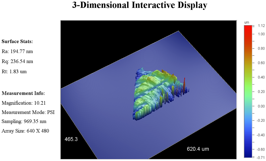
Surface roughness measurement on a single face of a fabricated microprism.
Although the novel layered tool trajectory method has displayed the feasibility of extending an effective stroke length of the existing FTS system, there are few areas of improvement for this proposed technique that should be conducted in the future. They include the following:
Only a single microprism has been studied for the feasibility of this proposed layered tool trajectory method. More free-form designs are to be studied to expand the effectiveness of this proposed method (i.e. array, off-axis and nonsymmetrical designs).
The dynamic response in the Z-axis retraction affects the geometrical accuracy and surface quality of workpiece. Hence, it is necessary to consider dynamic response compensation in the generation of layered tool trajectory.
Conclusion
Long-stroke FTS may be one of the possible ways to replace any existing FTS system with limited stroke length in order to fulfill greater surface height requirements. In this article, a novel method has been proposed to extend the limited stroke length without modifying an existing FTS system by generating layered tool trajectory. This proposed layered tool trajectory method has demonstrated the feasibility study of fabricating a microprism by FTS diamond turning. The height of a fabricated microprism has an error of 0.65 µm as compared to the designed height requirement. However, the achieved average surface roughness (Ra) is about 195 nm, which could be relatively high for diamond turning application. This is most likely caused by the dynamic response of the Z-axis movement during the Z-axis retraction in the layered tool trajectory. Finally, the proposed method has successfully extended an effective stroke length of the existing FTS system to about fivefold of its maximum possible stroke length. In the future work, more free-form surface designs are to be studied for the feasibility of this proposed layered tool trajectory method and the dynamic response compensation of Z-axis in the generation of layered tool trajectory.
Footnotes
Funding
This research received no specific grant from any funding agency in the public, commercial or not-for-profit sectors.