
Abstract
Metallic lattice structures manufactured using selective laser melting are widely used in fields such as aerospace and automobile industries in order to save material and reduce energy consumption. An essential element of metallic lattice structures design is determining their mechanical behaviors under loading conditions. Theoretical method based on beam theory has been proposed for evaluating the behaviors of the commonly used body-centered cubic lattice structures. However, it is difficult to predict theoretically the properties of the uniaxially reinforced lattice structures based on the body-centered cubic structures. Since the reinforced structures have superior strength to weight ratio and are deemed promising in lightweight-design applications, this article proposed a force-method-based theoretical method to calculate the mechanical properties of the body-centered cubic structure and its two types of uniaxially reinforced structures fabricated via selective laser melting. The finite element analysis and compression experiment study of selective laser melting samples made using Ti6Al4V powders demonstrated the validity of the proposed analytical method.
Introduction
Urgent demands for lightweight material are encouraging the applications of metallic lattice structures. Because a lattice structure consists of periodical unit cells, it has a higher ratio of strength to weight as compared with other stochastic lightweight materials, such as metal foam. 1 Early studies of the mechanical properties of metallic lattice structures dated to 2001, when Deshpande et al. fabricated an octet-truss lattice structure made from aluminum alloy using a “lost wax” investment method. Analytical methods of calculating the stiffness matrix and buckling surfaces of this structure were established, and relevant sample tests were also conducted. The results showed that this structure is stretching-dominated and verified the stretching-dominated criterion. 2 Later, Wallach et al. studied a triangular lattice structure made from aluminum alloy using both experimental and analytical methods, including the numerical relationship between its mechanical properties and the relative density of the structure. A finite element analysis (FEA) using truss elements was proposed and the provided results were in good agreement with the tests and analytical analysis. 3 Common metallic lattice structures that can be manufactured using a conventional process were compared by Wang et al. In their study, the Kagome lattice presented good resistance to inner plastic yielding and showed superior mechanical properties to tetrahedron and pyramid lattices. 4
These metallic lattice structures described above were fabricated using conventional techniques, which usually demands casting in multiple steps or using a tooled approach. 5 However, it is time-consuming and even impractical to fabricate metallic lattice structures using conventional processes when their geometrical features are too complicated or bulk materials with inferior manufacturability, such as titanium alloy (Ti6Al4V), are used. Now, with the application of additive manufacturing (AM), especially selective laser melting (SLM), metallic lattice structures can be manufactured on a relatively short-time scale, and the size of the unit can be on the micrometer scale. In the meantime, researchers have more design freedom such as fabricating novel topology-optimized structures consisted of non-cylinder struts.6,7 Moreover, due to its high-energy laser beam, SLM is suitable for fabricating metal parts that have high strength and few defects using various bulk materials.8–11. For example, the density of a titanium part fabricated using SLM can reach 99.9%, 12 and its strength can reach up to 1300 MPa. 13 Therefore, lattice structures manufactured using titanium alloy powder provide new business opportunities in sectors such as aerospace and medical implants.14–16
Unfortunately, limitations resulted from the SLM process should not be ignored. Fabricating parts with low-angle struts demands proper supportive structures,17,18 and it is impractical to design supportive structures for each inner low-angle strut in lattice structures. 19 Therefore, given this circumstance, low-angle struts should be avoided in designing lattice structures. The body-centered cubic (BCC) lattice structure can be well manufactured because all the inner struts incline properly. Additionally, the BCC structure has simple deform and failure modes during uniaxial and multiaxial compression. 20 Based on the homogenous deformation type and the symmetry of the unit, Ushijima et al. proposed a beam-theory-based analytical method to predict the initial stiffness and yield stress of BCC lattice structures. In this method, a force model of a BCC structure under a compressive load was simplified into a cantilever beam model. By calculating the internal forces and displacements of the free end of the beam, the uniaxial stiffness of the beam was calculated and deemed the initial stiffness of the entire structure. Using FEA and corresponding compressive tests, the authors found that the experimental data, FEA, and analytical predictions were in good agreement for BCC structures with low relative densities. 20 A similar analytical method was used by Babaee et al. 21 to study the mechanical properties of rhombic dodecahedron lattice structures. Gümrük and Mines investigated the compressive response of a BCC lattice structure made in 316L stainless steel. The material overlapping effect near the strut joints was considered when the beam-theory-based method was used; therefore, more reasonable predictions of initial stiffness and yield stresses were obtained. 22
Although the mechanical properties of BCC structures can be improved by increasing their relative densities, they still present relatively lower load-bearing capability because of their bending-dominated properties. Researchers noted that if some struts were added to the BCC unit, the specific stiffness and specific strength of corresponding structures, which can be called reinforced BCC structures, were improved significantly. Figure 1 shows the two types of reinforced BCC structures: BCCZ and f2BCC structures. Labeas and Sunaric 23 compared the mechanical properties of BCC structures and BCCZ structures and found that BCCZ exhibited much higher stiffness and buckling load. This phenomenon was also verified by Smith et al. when they proposed the finite element (FE) modeling of the compressive response of BCC and BCCZ lattice structures. In their projects, for BCC and BCCZ lattice structures with the same size (unit volume: 2.5 mm3, strut diameter: 0.2 mm), the strength of the BCCZ lattice was over six times larger than that of the BCC structure. 5 Although the BCCZ and f2BCC structures have been deemed promising in the lightweight-design field, 24 few theoretical studies have been conducted on the BCCZ and f2BCC reinforced structures as did on the BCC structures. Because the additional struts result in complicated and inhomogeneous deformation among struts in BCCZ or f2BCC unit, it is difficult to use beam theory to predict the mechanical response of lattice structures with complicated deformation models.
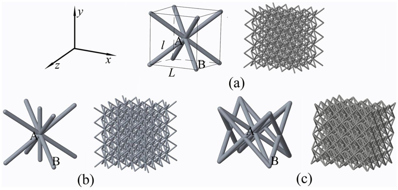
Lattice units and corresponding structures: (a) BCC, (b) BCCZ, and (c) f2BCC.
Therefore, this article describes an extension study of the beam theory used for predicting the mechanical response of metallic lattice structures manufactured using SLM. By utilizing the force method, the mechanical properties of both the BCC and its reinforced structures (BCCZ and f2BCC) were calculated efficiently and accurately. The rest of the article is organized as follows. The mechanical properties of BCC, BCCZ, and f2BCC structures were studied theoretically using the force method in section “Theoretical method.” Then, compressive sample tests and FEA are performed in section “Experimental study and FEA.” The results, analysis, and related discussion will be presented in section “Results and discussion.” Finally, the conclusions and suggestions for follow-up studies will be listed in section “Concluding remarks.”
Theoretical method
In this section, BCC, BCCZ, and f2BCC structures were analyzed to establish an analytical method of predicting their mechanical properties. As shown in Figure 1, a BCCZ unit is obtained by adding a vertical strut along the Y-axis based on the BCC unit, while an f2BCC unit is obtained by adding struts located along the diagonals of four sides of the cube. The positive direction of the Y-axis is the material stacking direction in the SLM process. Moreover, because this method is based on Euler–Bernoulli beam theory, all struts must be seen as slender beams, and the aspect ratio of strut AB (the ratio of the diameter to the length) in all three structures was set to 0.1.
Prediction of mechanical properties of the BCC structure
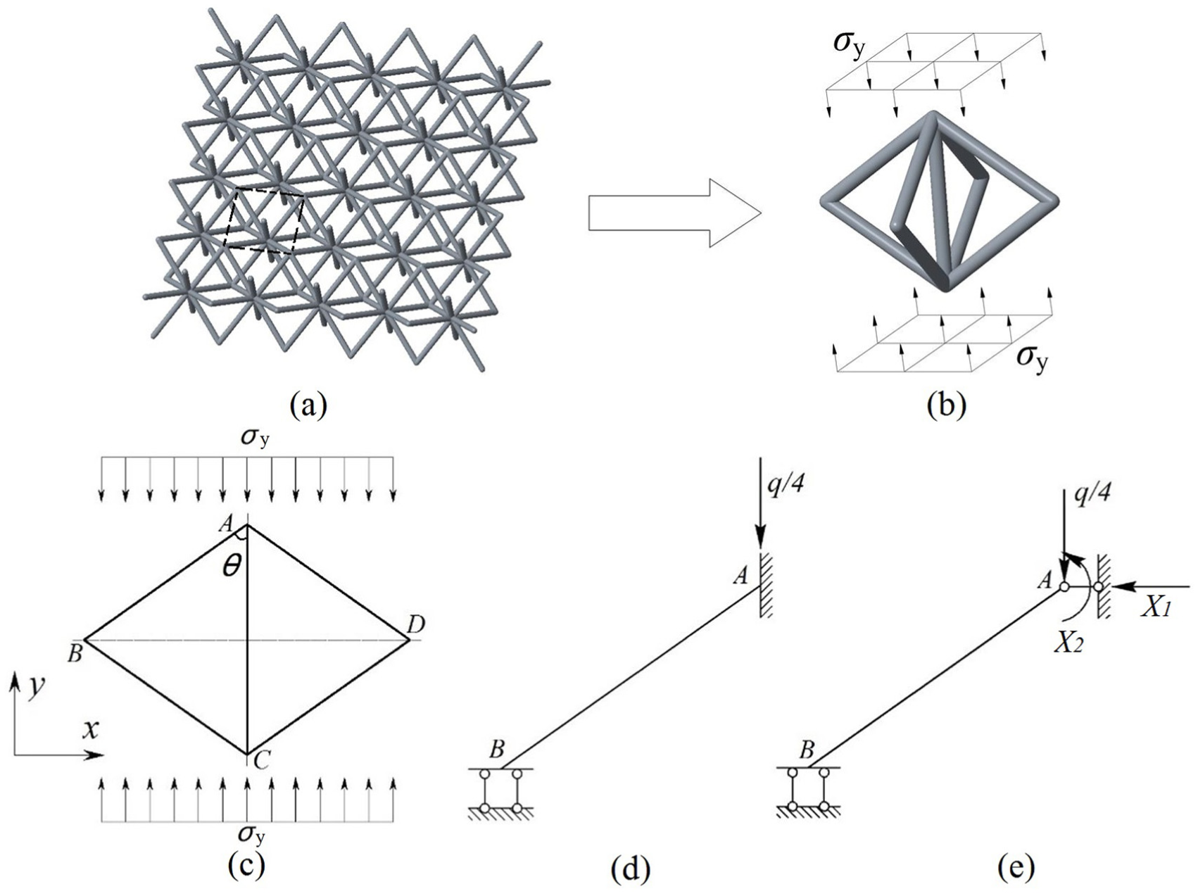
Because all struts in BCC structure deform homogeneously when a uniaxial load (along the Y-axis in Figure 2) is applied, strut AB was chosen out to build a force model based on the symmetry of the BCC unit as shown in Figure 2(a)–(d). Under this loading condition, point A moves vertically, while B moves horizontally with respect to point o in Figure 2(c). Therefore, the force model of strut AB was established in Figure 2(d). Note that if the force q is born by each unit, then q/4 is born by each strut.
(a) A layer of BCC structure, (b) equivalent BCC unit, (c) two-dimensional BCC unit under uniaxial loading condition, (d) force model of strut AB, and (e) fundamental system of strut AB.
Based on beam theory, strut AB can be deemed a beam with one degree of indeterminacy. The corresponding fundamental system of this beam is shown in Figure 2(e). The additional force X1 can be obtained using the force method equation

where Xi are the additional forces, Δ jp represents the displacement in the jth direction caused by the external loads, and δji represents the unit displacement in the jth direction caused by the ith additional force.
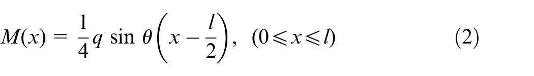
δji and Δjp can be calculated using Mohr’s integrals. The bending moment equation of the strut is therefore proposed as follows
The displacement of point A can be obtained via the unit-load method, and the displacement of the BCC unit is twice the displacement of point A
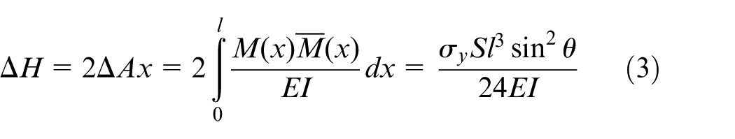
where ΔH is the compressional displacement of the BCC unit, Es represents the elastic modulus of the bulk material, and S is the base area of the design domain of the BCC unit, that is, the cube.
Force q equals the stress σ multiplied by the base area of the cube S; therefore, the equation for the equivalent elastic modulus and geometrical properties of the strut can be obtained
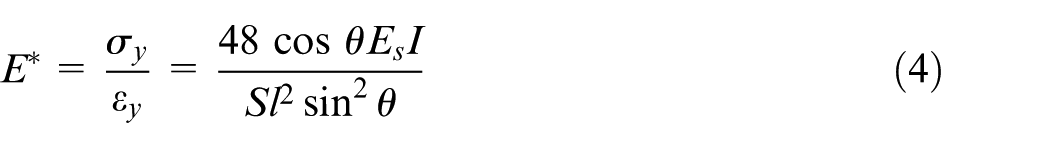
The above equation can be rewritten in the following form
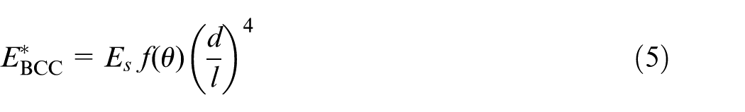
The force-method-based theoretical method for predicting the elastic response of BCC lattice structures was established. In the following subsections, this method is used to estimate the elastic properties of two reinforced structures.
Prediction of elastic response of BCCZ structure
Because of the vertical struts, the force model for the BCCZ structure is shown in Figure 3. Point A can be seen as supported by a fixed bearing, and then the strut AB is deemed a beam with two degrees of indeterminacy, as shown in Figure 3(d) and (e). Based on the force method and using equation (1), the additional forces X1 and X2 can be calculated. Using the unit-load method, the displacement of point A is as follows

(a) A layer of BCCZ structure, (b) equivalent BCCZ, (c) two-dimensional BCCZ unit under uniaxial loading condition, (d) force model of strut AB, and (e) fundamental system of strut AB.
Equation (6) shows that the compressive displacement of the BCCZ unit was also 0, which means that the strut AB will deform only if the fixed bearing moves. As the role of bearing is played by the vertical strut, the equivalent elastic modulus of the BCCZ has a superposition relationship
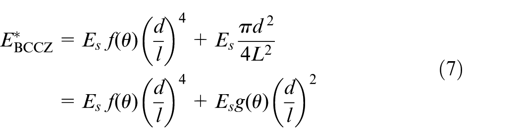
where L is the length of the edge of the design cube, as Figure 1(a) shows.
As equation (7) shows, the first item in the right-hand side of the equation is the elastic modulus of the BCC structure, and the second item is caused by the additional vertical strut.
Prediction of elastic response of f2BCC structure
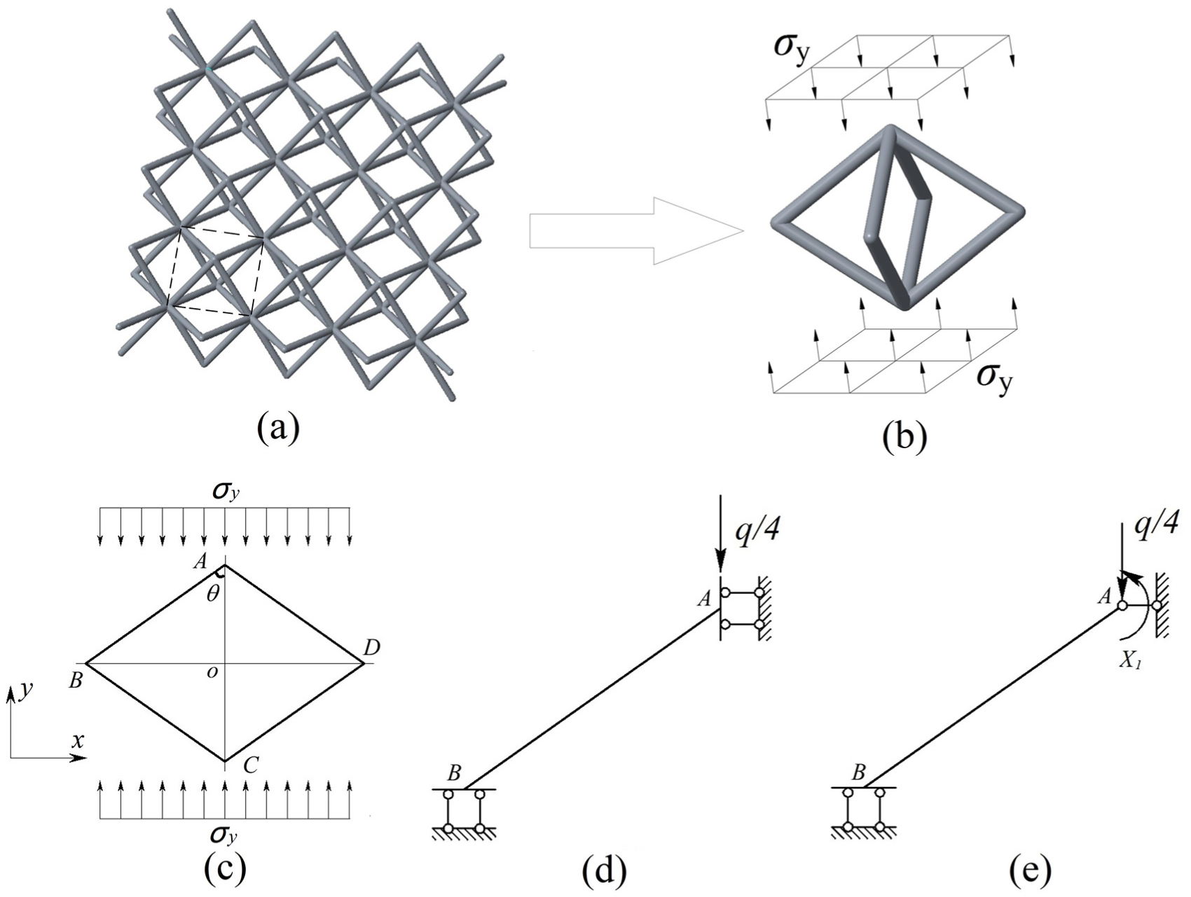
One layer of f2BCC lattice structure and its basic unit are shown in Figure 4(a) and (b). The basic unit consists of two simple subunits: a BCC unit (lighter color) and a face-centered cubic unit (FCC, darker color). As a result, the f2BCC unit has a more complicated topology. Then, the question becomes how these subunits deform when compressive load along the Y-axis is applied to the entire structure. Therefore, a previous study on an f2BCC unit using FEA under compressive load along the Y-axis was conducted. As Figure 4(d) shows, the difference between the displacements of point B2 and point B1 along the X-axis was recorded, and units with various strut aspect ratios (the ratio of the diameter to the length of the strut) were analyzed.
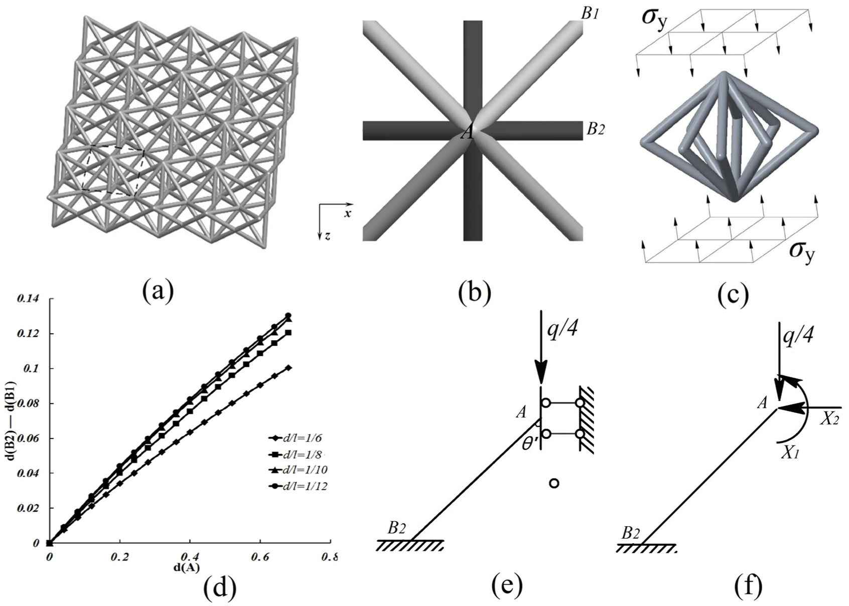
(a) A layer of f2BCC structure, (b) equivalent f2BCC unit, (c) two-dimensional f2BCC unit under uniaxial loading condition, (d) the difference between the x-axial displacement of point B1 and point B2, (e) the force model of strut AB2, and (f) fundamental system of strut AB2.
As Figure 4(d) shows, an obvious displacement difference of point B2 and point B1 along the X-axis was observed, which means that for the f2BCC unit, faster horizontal deformation occurs in the FCC subunit. However, because of the symmetry, strut AB2 cannot deform freely because it will be squeezed by the adjacent strut in the structure. We then assume that the beam model of strut AB2 is shown in Figure 4(e). Strut AB2 can be deemed a beam with two degrees of indeterminacy as shown in Figure 4(f).
Based on the force method and using equation (1), the additional forces X1 and X2 can be calculated. Then, the bending moment equation of AB2 is as follows

Equation (8) shows that there is only axial force on strut AB2, which means that the FCC subunit is stretching-dominated. Using the energy principle yields the following
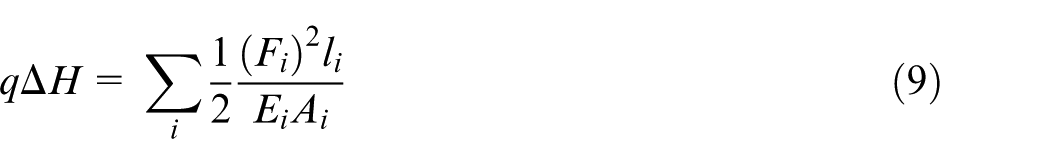
where Fi, li, Ei, and Ai are the axial force, length, elastic modulus, and area of the cross section of the ith strut, respectively.
From equation (9), the compressive displacement of the FCC subunit can be obtained, and its equivalent elastic modulus can be calculated as follows
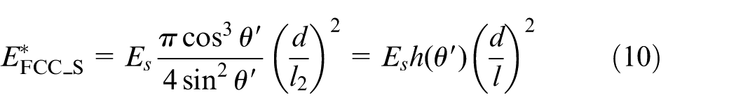
where l2 and θ′ are the length of the strut AB2 and the angle between the strut AB2 and the vertical direction, respectively.
Note that the strut AB1 is identical to the strut AB in section “Prediction of mechanical properties of the BCC structure,” and the equivalent elastic modulus of the f2BCC structure can be calculated as follows
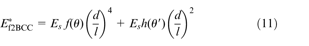
Equations (5), (7), and (11) reveal that there are exponential relationships between the elastic property and the geometrical factors of the three structures. Moreover, there is only a fourth-power term in equation (5), while additional square terms exist in equations (7) and (11) as a consequence of additional struts. Therefore, the stiffness of BCCZ and f2BCC structures will be improved significantly as compared with the basic BCC structure according to the theoretical methods. In section “Experimental study and FEA” an experimental study and FEA will be carried out in order to verify this conclusion.
Experimental study and FEA
In order to verify the theoretical method proposed in section “Theoretical method,” an experimental study and FEA were conducted in this section. First, uniaxial compression tests were conducted on Ti6Al4V samples fabricated using the three above-mentioned types of lattice structures. In this step, the engineering stress–strain diagrams were obtained, and the experimental data should be correlated with theoretical predictions. Then, FEA was carried out in the following step to illustrate the stress distribution and deformation type of the three structures under uniaxial loading conditions.
Equipment, material, and samples
The equipment used for fabricating these samples is an electro-optical system (EOS) M280 SLM system located in the Additive Manufacturing Research Center of Chongqing University, China. The effective build volume is 250 mm × 250 mm × 325 mm. The powders used for fabricating the samples were made using Ti6Al4V. A previous study on powder morphology showed that the maximum diameter of powders is around 30 µm.
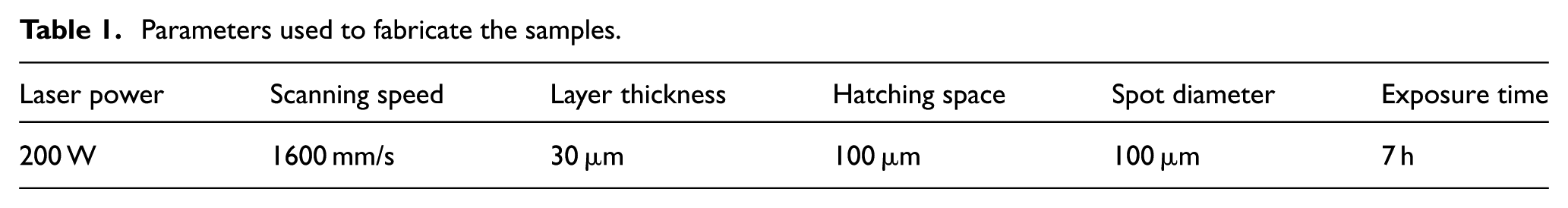
As Figure 5(a) shows, all samples are made as cubic blocks, and their size is 24 mm × 24 mm × 24 mm, that is, there are four cubic units on each edge. As mentioned above, the analytical method proposed in this article is based on Euler–Bernoulli beam theory, which demands the beam to be slender. Therefore, the diameter-to-length ratio of each strut is determined to be 0.1. The diameter of each strut is around 0.52 mm consequently. Computer-aided design (CAD) models of the structures were transformed into stereolithography (STL) files, which were imported into the EOS machine. Then, the samples were manufactured layer-by-layer in terms of corresponding two-dimensional (2D) images of cross sections. The parameters used to fabricate the samples are listed in Table 1.
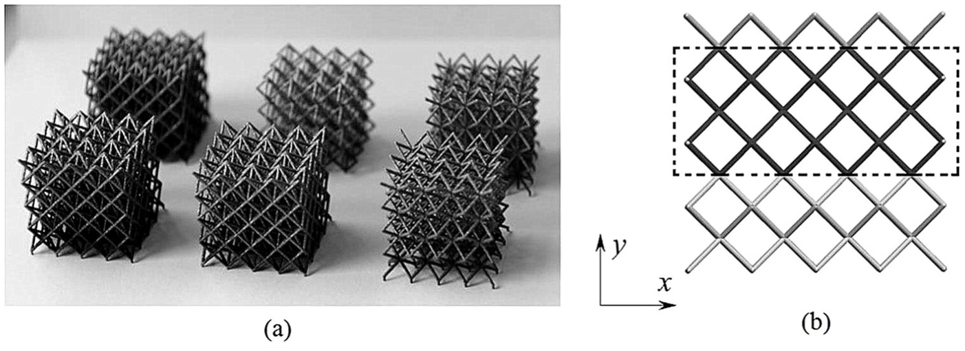
(a) Samples of Ti6Al4V structures and (b) the elevation view of the BCC structure.
Parameters used to fabricate the samples.
A series of uniaxial compressive tests were conducted on a universal test machine. These lattice samples were loaded in the build direction during SLM, namely the Y-axis direction. The displacement rates of the crosshead were properly set. Therefore, the strain speed was 0.005 per minute in each test (American Society for Testing and Materials (ASTM) standards). The displacement and reaction force of the crosshead were recorded during each compression test in order to plot the engineering stress–strain diagrams.
FEA
It is difficult to reveal the inner stress distribution in lattice structures using theoretical method proposed in section “Theoretical method” or experimental study. FEA can provide detailed inner stress distribution. Particularly, to lattice structures consisted of non-cylinder struts, such as gyroid lattice, FEA is an effective alternative to the theoretical study and is also an economical solution compared with the time-consuming and expensive sample tests. 19 Here, FEA was conducted to simulate the uniaxial compression response of the aforementioned lattice structures using ABAQUS commercial FE software.
To the BCC structure, the simulation approach called the continuum element model was conducted. In order to reduce the computation time, two layers of the BCC structure were chosen (the darker layers shown in Figure 5(b)). The two-layer model can show the interaction between adjacent units under compressive loading conditions. Figure 6 shows the continuum model of the BCC structure. Because of the symmetry, one-quarter FE model with symmetry boundary conditions of the two-layer structure was established. Similar modeling techniques were used when BCCZ and f2BCC structures were tackled.
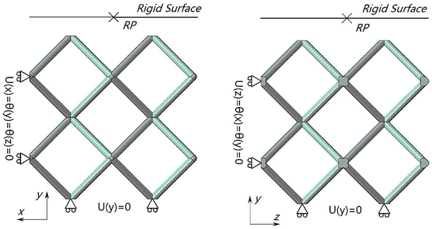
Boundary conditions for BCC structures.
In all the three FE models, analytical rigid surfaces were built and used as the crosshead in compression tests. Rigid and non-friction contact conditions were set between the rigid surface and the top surface of the structures. A reference point (RP in Figure 6) placed at the center of the surface has two functions: one is to apply the displacement boundary conditions to the models, and the other is to record the displacements and reaction forces from the structures in order to draw the engineering stress–strain curves. Two steps were established for each FE model after the default initial step. The first step was called “InContact,” in which the rigid surfaces would move downward properly and create the non-frictional contact relationship between the rigid surfaces and the structures. Then, the rigid surfaces compressed the structures in the next step, called “Press.” Moreover, all the material models were assumed to be isotropic, and the Mises yield criterion was used in the FEA analysis. Because the process parameters are similar to those in a previous work, 13 the material was set to Ti6Al4V, whose elastic modulus is 110 GPa and yield strength is 1110 MPa. When the stress reaches up to 1270 MPa, the plastic strain is 0.02.
Results and discussion
In order to analyze the validation of the theoretical method proposed in section “Theoretical method,” the engineering stress–strain curves based on the results obtained from the theoretical methods, FEA, and sample tests are depicted in Figures (7) and (9). Here, the bulk material properties used in the theoretical equations are similar to those in the FEA.
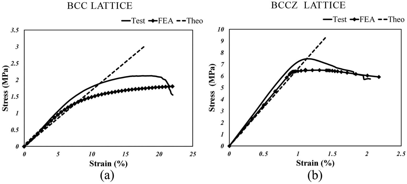
Stress–strain curves of (a) the BCC and (b) BCCZ structures.
Figure 7(a) shows the engineering stress–strain curves for the BCC structure based on the results of the theoretical analysis, FEA, and uniaxial compression tests. The solid line, the box line, and the dash line represent the results obtained from FEA, the theoretical method, and compression tests, respectively. To the BCC structure, the theoretical results are 16.88 MPa for the equivalent elastic modulus, while those from the FEA are around 20 MPa, which are slightly bigger than the theoretical predictions. The testing result shows that the elastic modulus is around 24 MPa.
From Figure 7(a), the mechanical properties of a BCC structure manufactured using SLM can be calculated via the force method proposed in section “Theoretical method.” However, the discrepancies between the theoretical analysis, FEA, and experimental study should not be ignored. During the elastic stage, the results obtained via theoretical analysis were smaller than the results obtained using the FEA and compression test. The main reason is that the overlapping effect in the joints of the structure was not taken into account. Therefore, the actual length of each strut is relatively shorter than corresponding CAD model. Based on equation (5), with the quadruplicate relationship between the aspect ratio of the strut and the equivalent elastic modulus, using the theoretical methods will lead to smaller results. This effect can be tackled using the calculation method for effective strut length proposed by Gümrük and Mines. 22 In this way, more reasonable results that are closer to the experimental data can be obtained.
Figure 7(b) shows the engineering stress–strain curves obtained for the BCCZ structures. The elastic moduli from the theoretical analysis, FEA, and experimental study are around 665, 712, and 775 MPa, respectively. The validation of equation (7) based on the force method can be verified by both FEA and the experimental study. Moving from the BCC structure to the BCCZ structure, the elastic modulus is increased from around 20 to around 700 MPa, while the relative density is just increased from around 16% to around 18%, as shown in Figure 8(b). Here, the relative densities were calculated via dividing the volume of a unit by the volume of its design cube. Although only a vertical strut was added in the BCC unit, it is obvious that the vertical strut becomes the main load-bearing strut in the BCCZ unit. From both Figure 7(a) and (b), the results from the compression tests are higher than those from the FEA and theoretical analysis. The deviations of the results on one hand resulted from residual stress in structures due to the rapid melting and cooling process during the SLM. On the other hand, partial melting powders attaching to the strut cause the variation of the diameter of struts, while the strut diameter is constant in the FEA and theoretical studies.
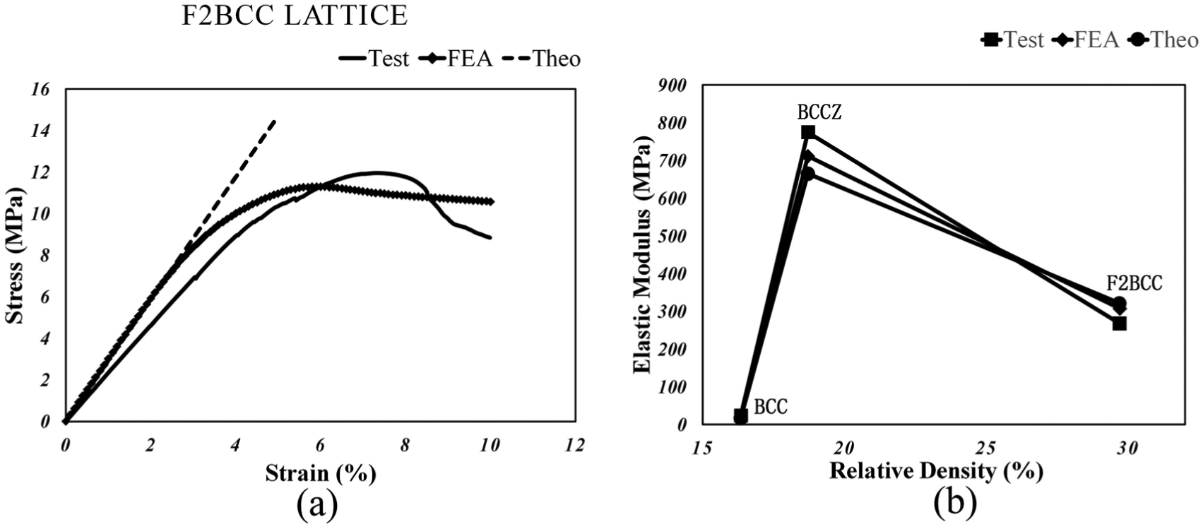
(a) Stress–strain curves of the f2BCC structure and (b) comparison of the three structures.
Figure 8(a) shows the engineering stress–strain curves of the f2BCCZ structures. The equivalent elastic moduli from the theoretical analysis, FEA, and experimental study are around 321, 307, and 268 MPa, respectively. Since these results are in good agreement, the force method proposed in section “Prediction of elastic response of f2BCC structure” can properly estimate the elastic properties of the complicated f2BCC structures. Moving from the BCC structure to the f2BCC structure, the elastic modulus is increased from around 20 to around 300 MPa, while the relative density is increased from around 16% to around 30%, as shown in Figure 8(b), and this change is caused by the fact that the FCC subunit added in the previous BCC unit becomes the main load-bearing part of the f2BCC unit. Thus, the assumption proposed in section “Prediction of elastic response of f2BCC structure” in which the FCC subunit is stretching-dominated under a compressive loading is verified by the FEA and experimental study when all struts in this structure are deemed slender beams. Another important phenomenon is that the theoretical result is larger than both the FEA and experimental data. This phenomenon is caused by the beam model proposed in section “Prediction of elastic response of f2BCC structure.” Point B2 is fixed in Figure 4 and the strut AB2 contains only axial force in the assumption; however, point B2 moves horizontally due to the movement of the whole unit, which has not been taken into account in the beam-based force model. Therefore, equation (11) is an approximate equation. To obtain a more accurate equation, the accurate deformation type of strut AB2 should be studied in the future.
Figure 9 shows the stresses distribution and deformation of BCC, BCCZ, and f2BCC structures under uniaxial compression loading conditions, obtained by FEA. The first column in this figure shows the situations in which the structures began to yield under compression loading along the Y-axis, while the second column shows the situation when the compressive process ended. Figure 9(a) shows the BCC structure during the compressive process, the deformation of the BCC structure is homogenous within the scale of the struts, and the stress distribution in each strut is nearly the same in the elastic or plastic stage. This is the reason why only one strut can be analyzed to estimate the properties of the entire BCC structure. Moreover, when the BCC structure began to yield, the highest-stress zones were located in the vicinity of strut nodes, where the limit bending moment of each strut took place. Figure 9(b) shows the situation when the BCCZ structure was under uniaxial loading conditions. The vertical struts are the main load-bearing struts because when the material in the vertical struts started to yield (the Mises stress in the vertical struts exceeded 1100 MPa), the highest stresses in the other struts were only around 200 MPa. When the vertical struts buckle, the 45° shear band was observed in compression experiments on BCCZ structures conducted by Smith et al. 5 Figure 9(c) illustrates the situation when the f2BCC structure was under uniaxial loading conditions. When the structure began to yield, the highest-stress zones were located in struts of the FCC subunits (the f2BCC unit is shown in the dashed-line square). The final deformation of the f2BCC structure shows that the struts of the FCC subunits buckled, while the struts of the BCC subunits illustrate homogenous stress distribution and deformation. This phenomenon correlates with the assumption proposed in the theoretical analysis: the struts of FCC subunits bear mainly axial forces.
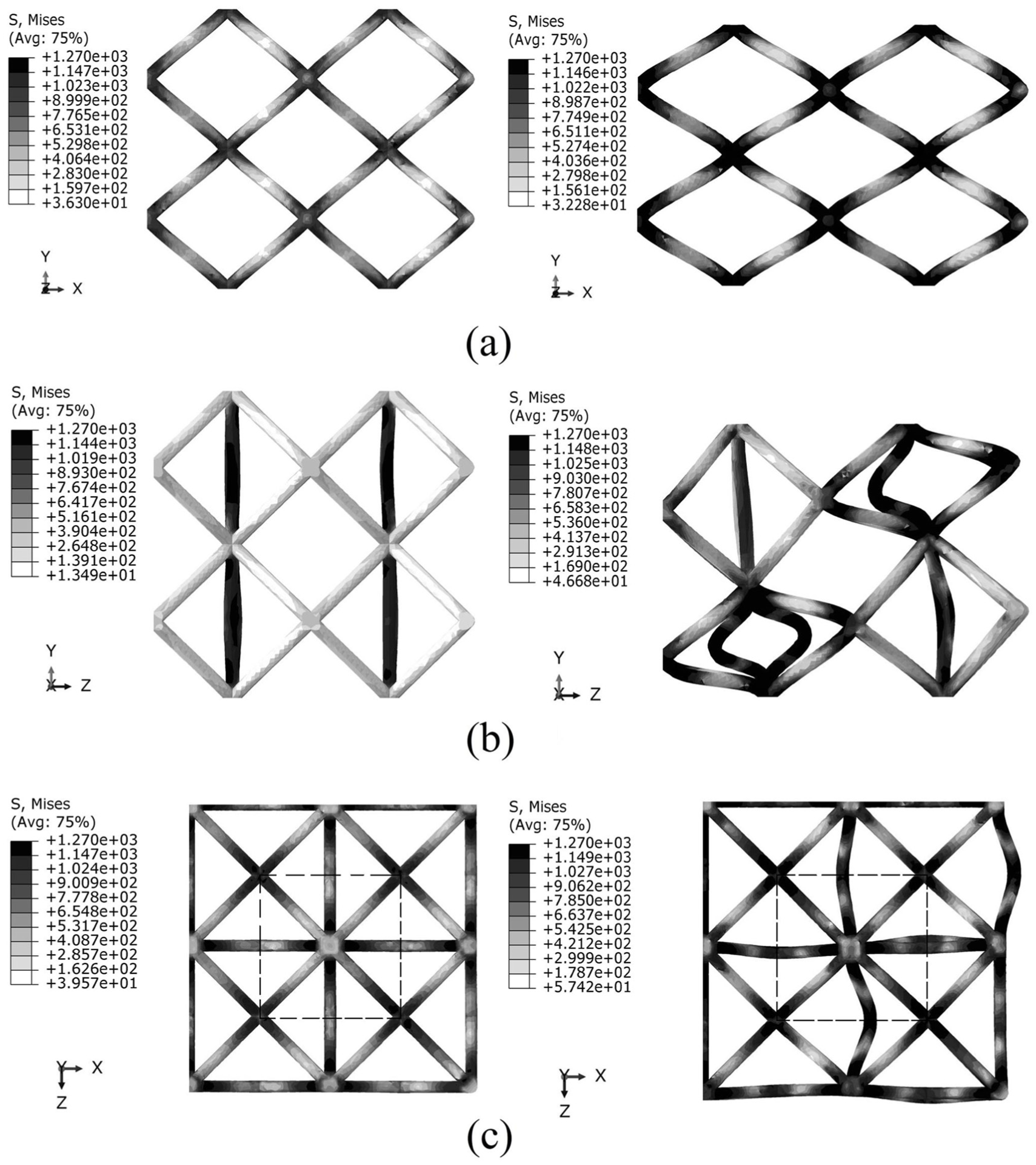
Stresses distribution and deformation of the structures: (a) BCC, (b) BCCZ, and (c) f2BCC. Compression loads were applied along the Y-axis.
From the above discussion, predictions of the mechanical properties of BCC, BCCZ, and f2BCC structures made using theoretical equations based on the force method were verified by both FEA and compression experiments. Further studies will be carried out in the following facets. First, the plastic properties of the three structures, especially the uniaxial-reinforced structures, will be studied. Unlike a BCC structure, which has a simple failure mode, it is difficult to propose accurate failure modes of BCCZ and f2BCC lattice structures which have more complicated yield criteria because of the additional struts. Second, more comparative FEA and experimental studies will be conducted on these structures with different aspect ratio of struts. In this scenario, the theoretical equations proposed in this article will be verified and modified as the struts with thicker diameter will not be simply deemed slender beams. Third, the SLM process parameters and heat treatment procedures were not taken into account in this study. Corresponding effects will be considered in order to evaluate the mechanical properties of these structures fabricated by the SLM process more accurately.
Concluding remarks
This article presents a force-method-based theoretical method for predicting the mechanical properties of BCC structures and its uniaxial-reinforced BCCZ and f2BCC structures fabricated using the current SLM process. The difficulty of calculating theoretically the mechanical properties of the reinforced structures, which have inhomogeneous deformation characteristics, was overcome via the proposed theoretical approach.
The cubic samples of the aforementioned lattice structures, in which the length of each edge is 24 mm, were modeled and manufactured in Ti6Al4V powder via SLM. To all inner units, their edge length is 6 mm and the diameter of each unit is around 0.52 mm.
The force model of the BCC structure under compression loading was simplified to a slender beam with one degree of indetermination. The equivalent elastic modulus of the BCC sample, whose relative density was round 16%, was calculated to be 16.88 MPa using the proposed equation, while those values obtained via FEA and the uniaxial compression test are 20 and 24 MPa, respectively.
The BCCZ structure, whose relative density is round 18%, is obtained via adding a vertical strut in each BCC unit. Its force model was simplified to a slender beam with two degrees of indetermination. Then, the equivalent elastic moduli were calculated to be 665, 712, and 775 MPa via the proposed theoretical equation, FEA, and experimental study, respectively.
The f2BCC structure, with the highest relative density around 30%, was obtained via adding cross struts in each BCC unit. Its force model was simplified to a slender beam with two degrees of indetermination. The equivalent elastic moduli were calculated to be 321, 307, and 268 MPa via the proposed theoretical equation, FEA, and experimental study, respectively.
The equivalent elastic moduli for each structure predicted by the three methods were quite close; therefore, the validity of this theoretical method was verified via FEA and compression tests on SLM samples. Comparing the properties of the BCC structure with its two uniaxial-reinforced structures, the latter structures present over 10 times stiffness to the original BCC structure while their relative densities are less than twice of that of the BCC structure, which demonstrate the reinforce structures are promising in lightweight-design application.
Because all the struts in these structures were thought of as slender beams, more FEA and sample experiments on these structures with various strut aspect ratios will be conducted. The validity of the proposed method will be evaluated when the influence caused by the diameter of struts cannot be ignored. Subsequently, the proposed theoretical equations will be revised to expanding their applied range. Moreover, the plastic properties of the BCCZ and f2BCC structures, the effects on their mechanical response caused by the SLM process, and the appropriate heat treatment measures used to eliminate residual stresses will be examined in the following research.
Footnotes
Appendix 1
Acknowledgements
The authors expressed their sincere thanks to the Additive Manufacturing Research Center of Chongqing University (China) for the manufacturing and testing of the Ti6Al4V samples.
Declaration of conflicting interests
The author(s) declared no potential conflicts of interest with respect to the research, authorship, and/or publication of this article.
Funding
The author(s) disclosed receipt of the following financial support for the research, authorship, and/or publication of this article: This study was supported by the National Science Foundation of China (No: 51405046) and the Chongqing Graduate Student Research Innovation Project (No: CYB14011).