
Abstract
Ultrasonic-assisted machining is an advanced method which allows significant improvements in processing of materials. In this study, a finite element model is developed to study the effect of ultrasonic vibration on machinability of AISI 304 stainless steel in which the results are compared with conventional cutting process. A pneumatic quick-stop device and an optical microscope are applied to validate the simulation results by measuring shear angle and sticky region experimentally. As a result, the analysis of heat generation in primary and secondary deformation zones shows that temperature increases in the primary zone when ultrasonic vibration is used, while a significant reduction in temperature is seen in the tool–chip contact zone. This area is considerably effective on the length of sticky region. Moreover, the influence of cutting speed and feed rate on tool–chip engagement time is investigated by the analysis of cutting force profile.
Keywords
Introduction
Ultrasonic-assisted turning (UAT) is one of the non-conventional machining operations which is based on intermittent cutting of materials. In this process, high-frequency vibrations (about 20 kHz) of small amplitude (4–15 µm) are added during the motion of cutting tool.1–3 Accordingly, this process indicates a range of improvements compared to the conventional turning (CT), namely, reduction in power consumption and enhancement of surface finish.4–6 In general, the effective factors in primary and secondary deformation zones are investigated to improve machinability of various types of materials. 7 Among these factors, shear angle is directly effective on the cutting force, tool–chip contact length, as well as heat generation in the tool–chip interface, consequently. However, increase in frictional force between tool and chip interface causes dissipation of input power and reduction in surface quality and tool life.8,9 As a widespread method, lubricants are used to overcome this problem. But a great variety of cutting parameters and external factors (e.g. chemical reaction, pressure, and temperature) will affect the lubricant efficiency. Thus, study on the use of ultrasonic vibrations to evaluate this matter is being carried out by researchers. However, some experimental and theoretical research works have been performed on various aspects of ultrasonic vibrations;10–12 this process needs more study so that it can be industrialized adequately. Before working on UAT, a comprehensive knowledge of basic metal cutting is required. Therefore, a couple of helpful studies related to the shear angle and tool–chip contact length are reviewed. Toropov and Ko 13 applied a slip-line solution to develop a new equation for determination of tool–chip contact length in orthogonal cutting process when the cutting tool is flat-faced. It was claimed that the prediction of proposed model is in good agreement with the cutting tests. Subsequently, Toropov and Ko 14 represented a new equation for the prediction of shear angle in orthogonal cutting process which is based on the normal material properties and cutting condition, without being influenced by any coefficient obtained in the experiments. They verified the presented equation by running some experimental tests on steel and aluminum alloy. In order to investigate tool wear in machining of Ti6Al4V titanium alloy, Bahi et al. 15 studied tool–chip contact zone to clarify the tribological condition. An analytical–numerical method was used to analyze this zone. They also discussed the effect of cutting parameters on sticky length in tool–chip interface. In another work, Ozlu et al. 16 reported that the sticky region is reduced by an increase in cutting speed, and the tool–chip contact length is mostly sliding. Furthermore, it was shown that the total tool–chip contact length is generally three to five times the feed rate. Totally, by reviewing studies represented above, the more the shear angle is higher and deformed chip thickness plus sticky region is smaller, the productivity of cutting process is higher. In addition, it has been proved that applying ultrasonic vibrations in the metal cutting has a certain positive effect on machining performance.17,18 However, evaluation of shear angle, deformed chip, and sticky region in UAT has rarely been exerted. On the other hand, covering all aspects of cutting process in theoretical and experimental works may not be adequately practicable due to the general complexity of the metal cutting process. Therefore, applying finite element method (FEM) could be helpful to comprehend different aspects of this process.
Despite a large number of simulation works on conventional machining, simulating the process of ultrasonic-assisted machining is still in the primary steps. As a rare study, Babitsky et al. 19 implemented UAT equipment to turn Inconel 718 superalloy. They developed a simulation model to predict cutting forces generated during UAT and CT. As a result, it was stated that the average cutting force is smaller in UAT compared to the CT. In another study, Mitrofanov et al. 20 simulated this process to analyze the effect of ultrasonic vibration on heat generation in the primary cutting zone. It was concluded that the temperature in the cutting zone in UAT is 15% higher than that obtained in CT. The same result has been achieved by Ahmed et al. 21 It was also noted that the use of friction criterion is significantly effective for the temperature distribution in the cutting zone. Amini et al. 22 tried to represent a finite element (FE) model for the prediction of cutting forces in the UAT process. At the end, it was concluded that the effect of clearance angle on the magnitude of the cutting force was insignificant, while smaller tool rake angle produced higher cutting force.
In this study, FE simulation of conventional and UAT process was conducted to analyze the effect of ultrasonic vibrations on metal cutting process. The simulation results were validated by running the experimental UAT in which the shear angle was measured at all cutting conditions using a pneumatic quick-stop device (QSD) and an optical microscope. Furthermore, the temperature on the tool faces generated in UAT and CT, and its effects on frictional behavior at tool–chip contact length (sticky zone), was studied. Moreover, the influence of cutting parameters on cutting force and their effects on tool–chip engagement time in UAT are also simulated.
FE modeling and experimental setup
As a well-known boundary condition for simulation of CT, the cutting tool is selected as a fixed object and the workpiece moves in the direction of cutting speed with constant velocity (Vc). A harmonic motion should be superimposed on the cutting tool in the tangential direction (parallel to the cutting speed direction) for the simulation of UAT, shown in Figure 1. The tool position


where t and a are time and vibration amplitude, respectively.
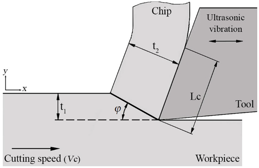
Relative movements of the cutting tool and workpiece.
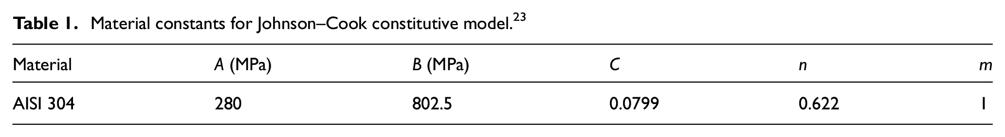
In this work, an updated Lagrangian formulation has been used to simulate chip formation and to remesh the workpiece when the elements of the mesh are too distorted. Moreover, higher mesh density compared to other areas was applied in the cutting zone due to large gradients of strain, strain rate, and temperature in this area. The workpiece material and the cutting tool were AISI 304 stainless steel and cemented carbide, respectively. The cutting tool was defined as a rigid body and the workpiece as a plastic object where the Johnson–Cook flow stress model (equation (3)) was used to represent the workpiece material constitutive behavior
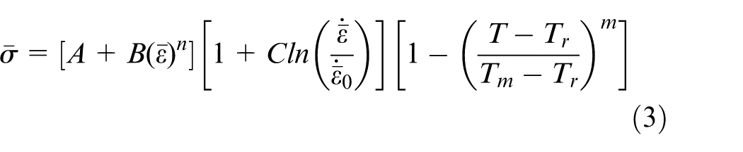
where A, B, C, n, and m are the yield strength, the hardening modulus, the strain rate sensitivity, the strain-hardening, and the thermal softening exponent, respectively (given in Table 1). Also,
Material constants for Johnson–Cook constitutive model. 23
To model the friction in the tool–workpiece contact, constant shear model was utilized (equation (4)). In this equation, k is the shear flow stress of the working material at the tool–chip interface and m is the constant shear friction factor which is equal to 0.6. However, an iterative procedure should be carried out if the predicted values are not in good agreement with the experiments 25

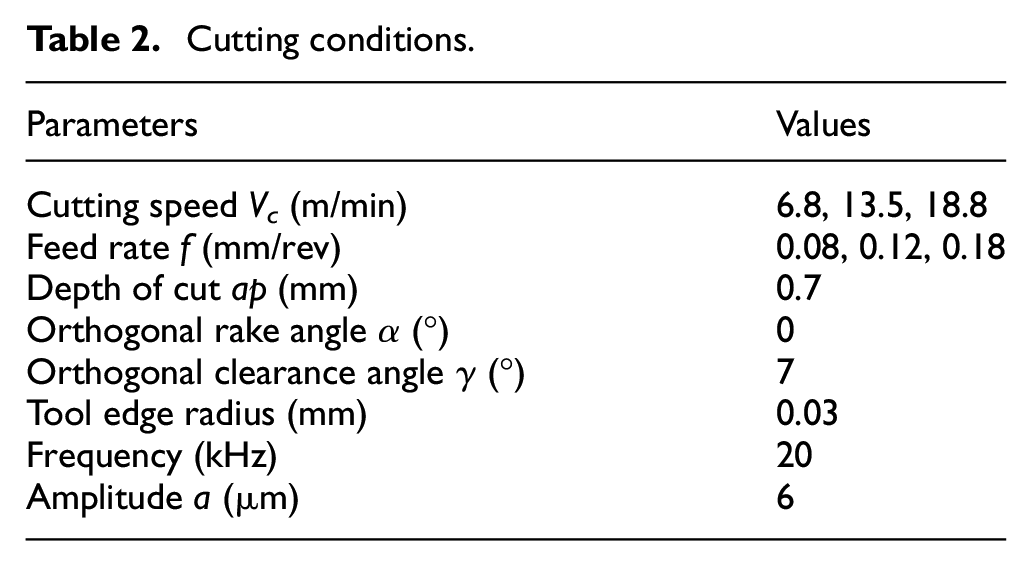
In order to verify the model developed here, a series of orthogonal cutting tests were conducted on the universal lathe (Tabriz-TN52). The cutting parameters are listed in Table 2. In general, there are some limitations in vibration machining during selection of cutting parameters, particularly in the selection of feed rate and cutting speed. Accordingly, feed rate should be chosen in a proper range so that the QSD can be effective. In the low and high feed rates, chip tends to break during the preparation or cutting process. Therefore, a medium range of this parameter was defined. In addition, a critical cutting speed is commonly taken into account. Regarding equation (5), the cutting speed should be lower than the critical cutting speed (

Cutting conditions.
To meet the orthogonal cutting process, the workpiece was prepared in cylindrical form and the insert nose was driven out from the engagement. The workpiece material was AISI 304 stainless steel with 47 mm diameter and 0.7 mm thickness. A flat-faced cemented carbide (Cerametal Company, China) insert was selected in this study, as illustrated in Figure 2. In order to measure shear angle and sticky region during the cutting process, a QSD is required. Due to using ultrasonic equipment, QSD should be able to take vibratory cutting tool away from the cutting zone. Hence, a pneumatic QSD was used (Figure 3). Accordingly, a pin goes through two bushes where one of them is mounted on L-shaped plane (which holds vibratory tool) and another one is on the body of QSD. If this pin exits from the bush connected to the body, then the spring force causes a quick-stop to occur. The pneumatic jack is considered to exit this pin. Furthermore, the vibratory cutting tool including an ultrasonic transducer, booster, horn, and cutting tool has been utilized to run UAT. The horn was made of stainless steel, and its resonance frequency is about 20 kHz. After running the experiments in the dry cutting condition, a vision measuring machine (VMM) was utilized to measure shear angle and sticky region of tool–chip contact length.
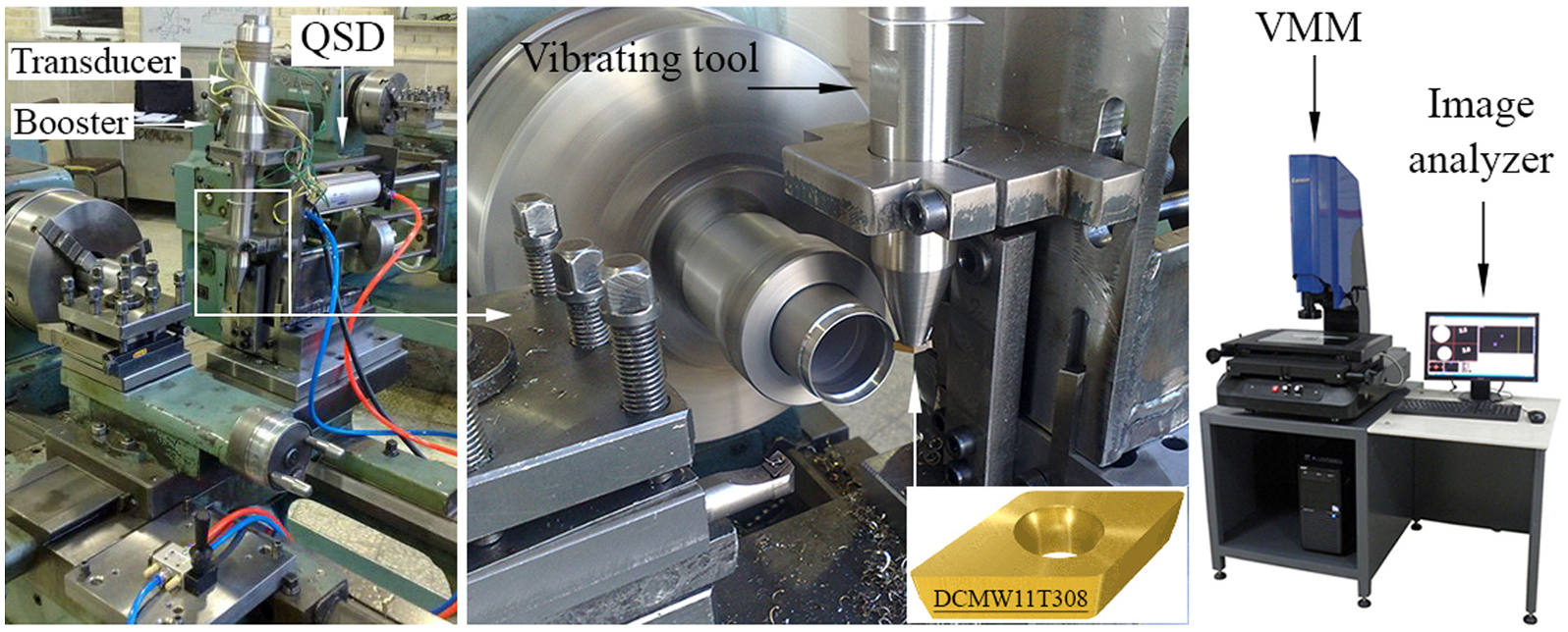
Applied instruments.
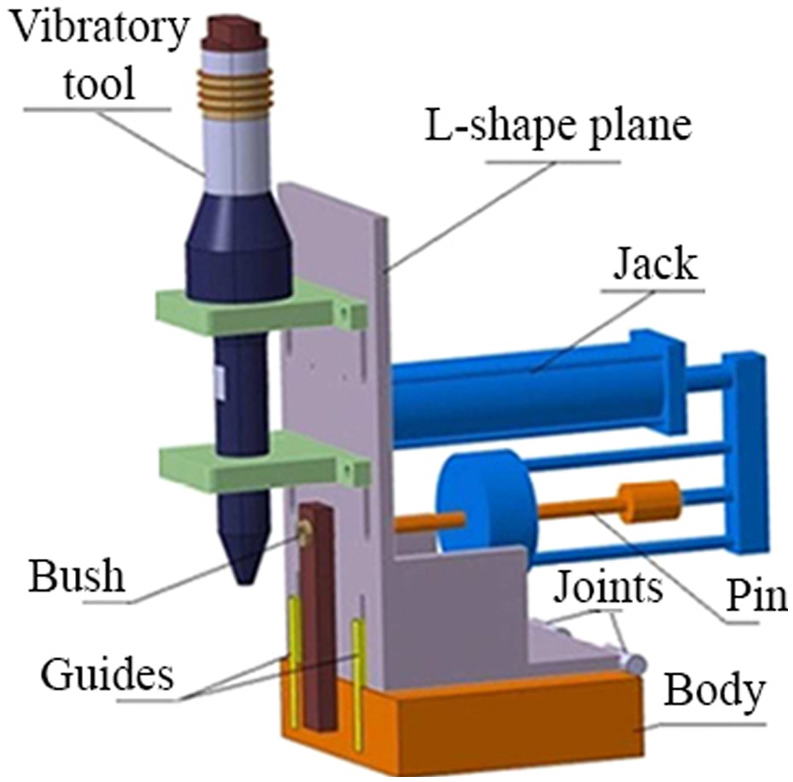
Quick-stop device.
Results and discussions
As can be seen in Figure 4, simulation of turning operation has been carried out using the method of CT and UAT. While a constant relative movement existed between tool and workpiece in CT operation, a harmonic movement in the tangential direction to the surface of the workpiece was superimposed on the cutting tool in the simulation of UAT. Figure 4 shows one cycle of cutting process when the vibrated tool was applied. Accordingly, a linear movement based on equation (1) was superimposed on the cutting tool in UAT. One cycle of the UAT can be divided into eight stages. During the first and second stages, the cutting tool starts approaching the chip, and in the third and fourth stages, it penetrates into the workpiece which results in chip formation. The stress becomes the maximum at these stages due to higher plastic work requirement and the friction between tool and chip increases when deformed chip flows out on the rake face. Afterward, the cutting tool starts its reverse motion, illustrated in stages 5 and 6. The stress in the primary cutting zone reaches its lowest value, which is clearly seen in stage 6. At the end, the cutting tool fully separates from the chip and goes to the starting point in the last stage.
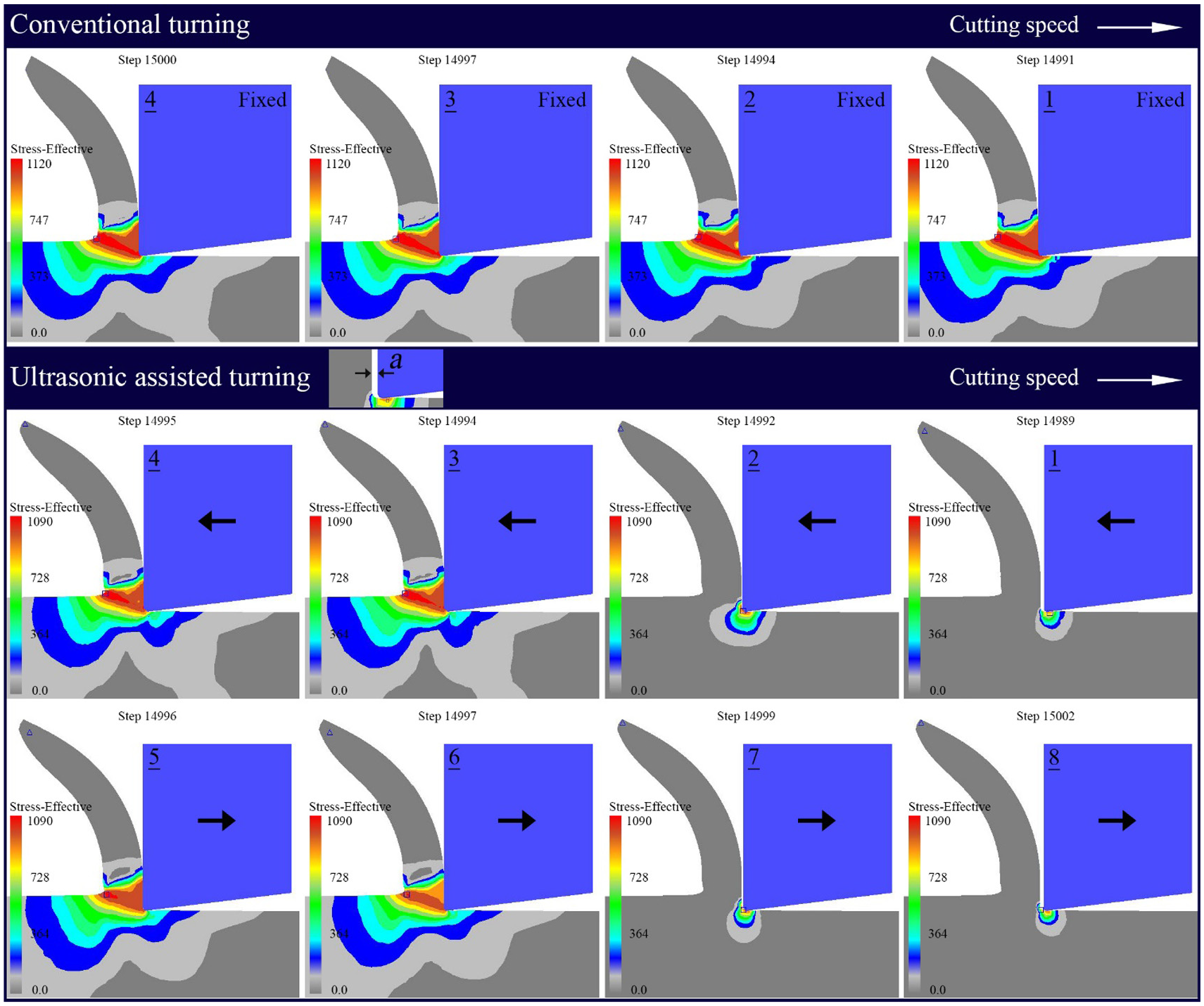
Simulation of conventional and ultrasonic-assisted turning (Vc = 13.5 m/min, f = 0.12 mm/rev).
Shear angle
After running each experiment, the cutting operation was stopped using a QSD and then a slice of workpiece was separated in order to evaluate different aspects of chip geometry (see Figure 5). The angle between shear plane and moving direction of uncut chip is shear angle. In this experiment, the separated specimens were grinded and then the shear angle was measured using a VMM. Afterward, the results were compared with those obtained by DEFORM 2D software after running the simulations. Due to low repeatability in the measurement of shear angle, all experiments were repeated three times and the average value of the achieved results was considered to verify the results of the simulation model. Figure 6 illustrates experimentally measured shear angles with their standard deviations.
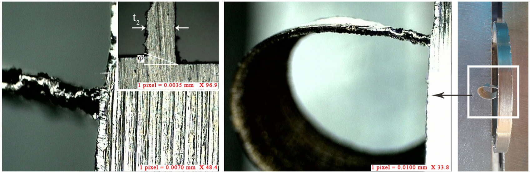
Measuring shear angle and deformed chip thickness in experiments.
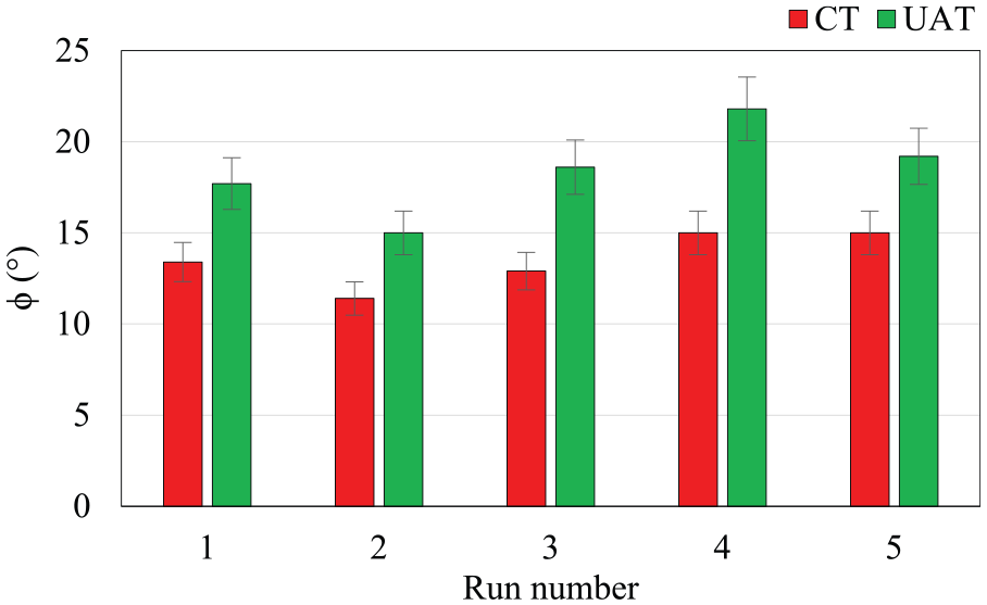
Measured shear angles in experiments.
The comparison results in Table 3 show that the predicted and experimental values are in good agreement. Generally, the analysis of shear angle shows this factor increased in all cutting conditions when ultrasonic vibrations were implemented in the turning of AISI 304 stainless steel.
Shear angle measured in experiments and simulations.
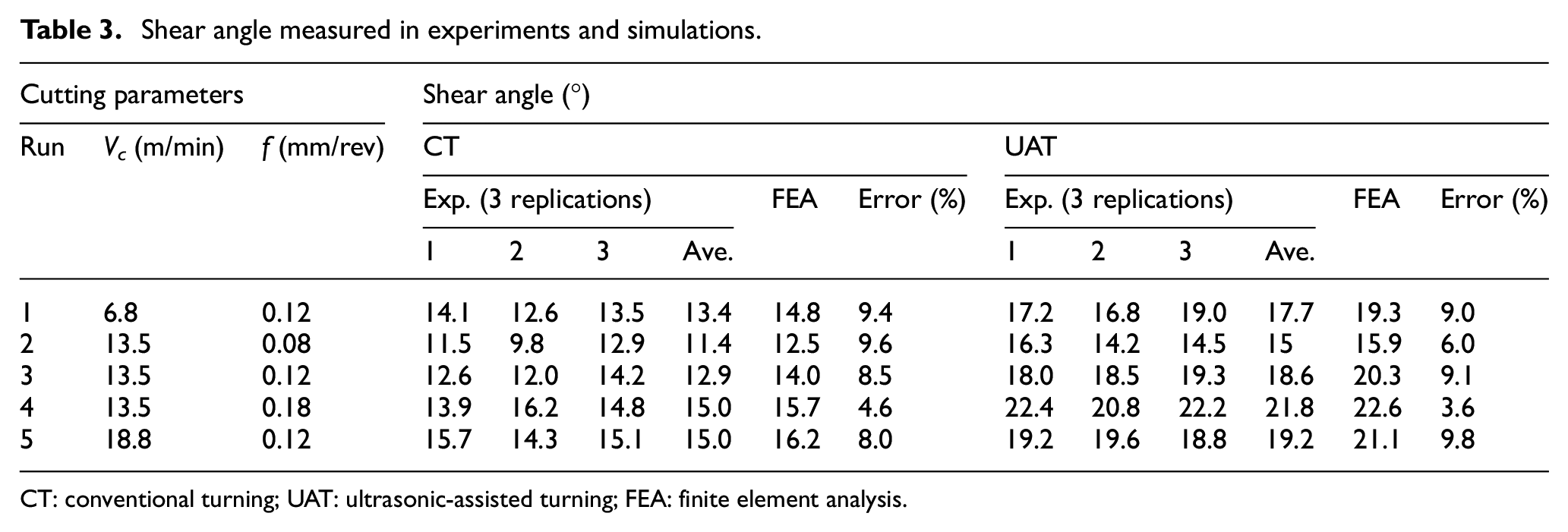
CT: conventional turning; UAT: ultrasonic-assisted turning; FEA: finite element analysis.
To know how the shear angle can be increased in the primary cutting zone, several studies were carried out, in which the ideal value is 45° when deformed chip thickness may be equal to uncut chip thickness. Increase in the value of this factor results in some improvements in the turning operation, such as reduction in deformed chip thickness causing a decrease in tool–chip contact length and power consumption. 26 Regarding Figure 7, influence of ultrasonic vibrations on the shear angle, deformed chip thickness, and strain-effective was studied. Comparison of CT with UAT in the same step shows that shear angle increased when linear vibration was added to the cutting tool. This event caused deformed chip thickness in UAT to be lower than the one obtained in CT. In this condition, the chip compression ratio increases, which is followed by an increase in the deformed chip length. This can be clearly seen when there was an increase in the strain value of deformed chip during UAT. This condition could be effective for temperature distribution in the sticky region and cutting force as discussed in the following sections.
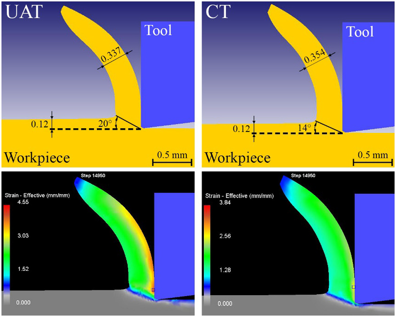
Shear angle, chip thickness, and strain-effective in deformed chip during CT and UAT.
Cutting force
Based on Figure 8, this type of cutting force profile was generally obtained under all cutting conditions. Accordingly, the cutting force was stabilized quickly after running the CT operation, while an oscillation motion is seen during UAT, due to harmonic movement of cutting tool. To clarify this motion, a short period of this process was separated and magnified (0.005–0.0052 s). During tool–chip engagement, the cutting force increased to its peak and then decreased to zero when the cutting tool disengaged completely. Considering this figure, the peak of cutting force in UAT is approximately equal to the CT, while the average value of cutting force is greatly smaller in UAT compared to the CT, in which it is 106 and 430 N for UAT and CT, respectively.
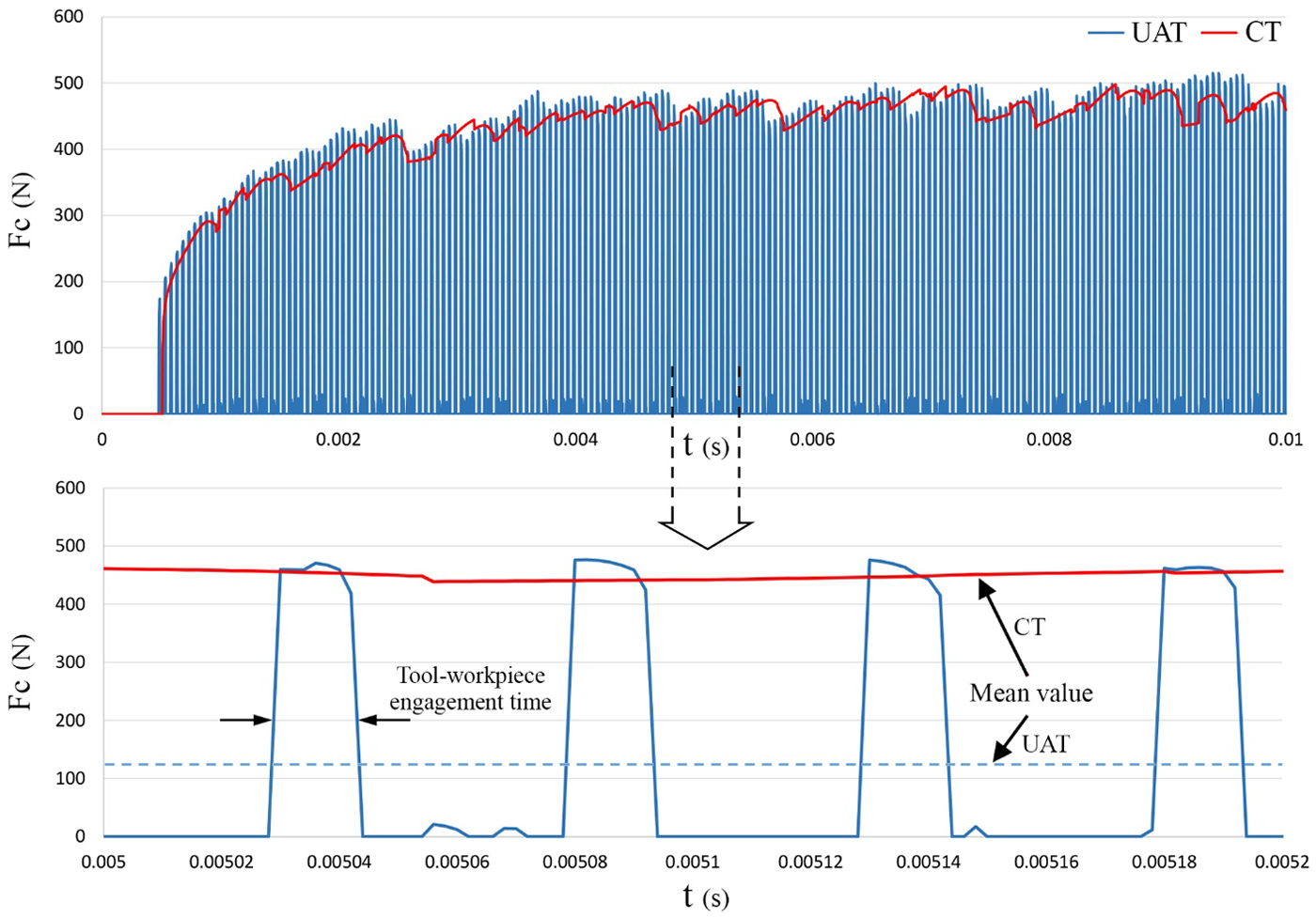
Cutting force profile during CT and UAT (Vc = 13.5 m/min, f = 0.12 mm/rev).
Figure 9 shows that an increase in cutting speed results in an increase in engagement time in UAT. This increment continues so that the cutting speed reaches the critical value. More than this value, the outputs of ultrasonic vibrations show no difference with the CT method. Furthermore, increase in feed rate at a constant cutting speed caused an increase in cutting force using both CT and UAT methods. It should be noted that the force values presented in Figures 8 and 9 result from the simulations.
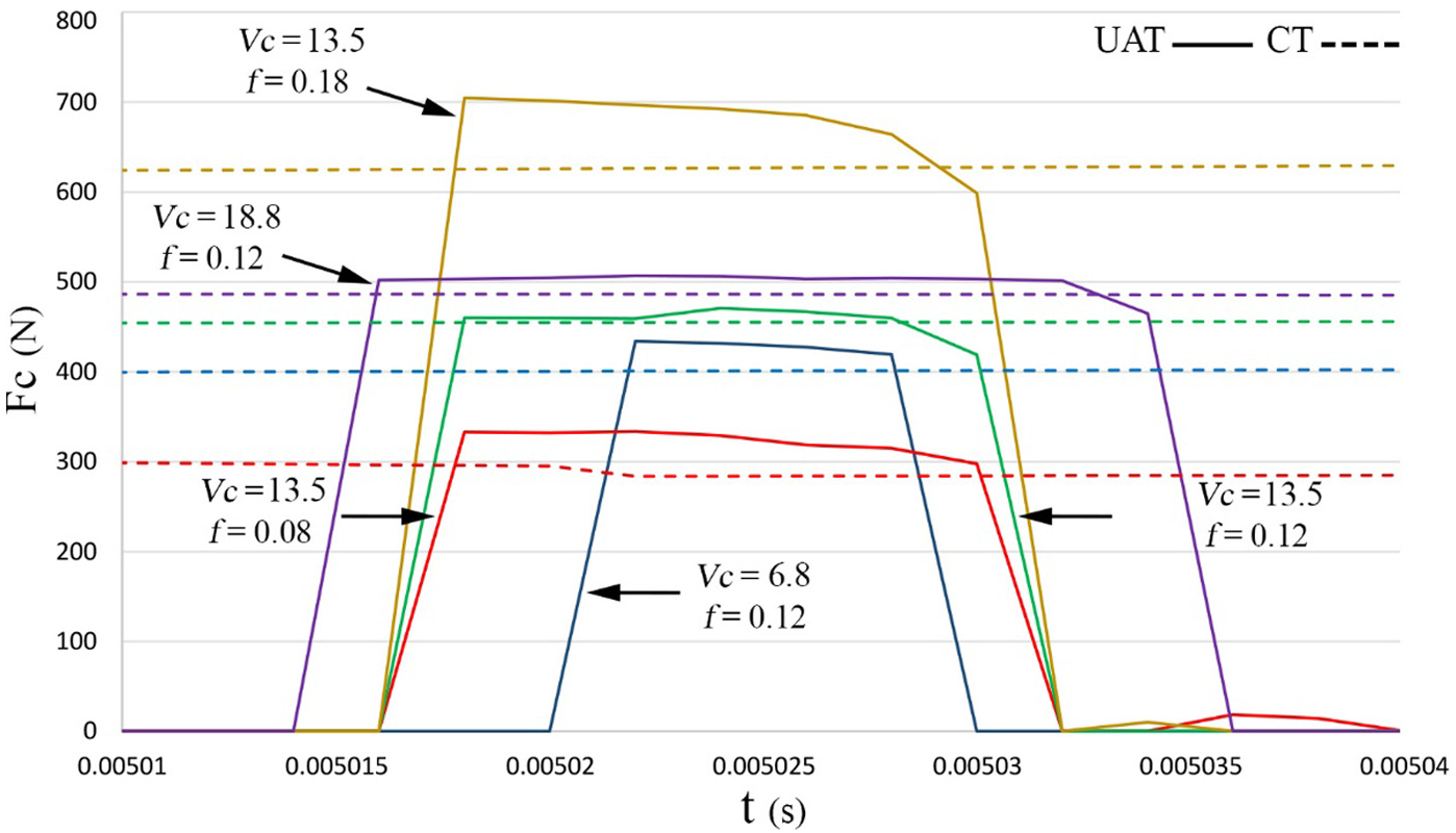
Comparison of cutting force at different cutting speeds (m/min) and feed rates (mm/rev).
Heat generation and tool–chip contact zone
On one hand, the simulation results revealed that the temperature in the primary cutting zone slightly increased when ultrasonic vibrations have been superimposed on the cutting tool. This could be explained by additional energy coming into the cutting system with ultrasonic vibrations. 27 On the other hand, the FE analysis of the heat generation showed that lower temperature was generated on the tool rake face in the UAT, which is an important area due to frictional properties between tool and chip (Figure 10). Lower temperature on the tool rake face causes lower sticky friction in the secondary deformation zone, which results in improvement in the desired factors of machinability. This decrement in the temperature and then in sticky friction can be explained by reduction in contact time and passing the air when the vibrated cutting tool disengages the chip. Therefore, an increase in amplitude (a) and frequency (F) decreases engagement time, resulting in lower friction and temperature on the tool rake face. Furthermore, it has been proved theoretically by Chou, 28 who represented a dimensionless variable (Ω) named the cutting seizure number. It is defined as the ratio of elastic strain energy (tool elastic energy) to the surface energy within per unit volume at tool–chip interface. It was shown that larger tool elastic energy reduces tool–chip sticky length. Thus, the following relation was expressed as


Temperature distribution on tool rake face and sticky region in CT and UAT (Vc = 18.8 m/min, f = 0.18 mm/rev).
With consideration of maximum linear vibration of cutting tool (
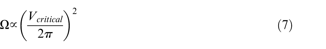
With respect to equation (7), higher amplitude (a) and higher frequency (F) in UAT increase maximum linear vibration which is proportional to Ω. This increment reduces the temperature and consequently the sticky length, which cannot occur in CT when maximum linear vibration of cutting tool is equal to zero.
However, it may not be the only reason why the shear angle increased when ultrasonic vibrations were applied. Based on equation (8) represented by Özel and Zeren, 29 the sticky region decreases with an increase in shear angle
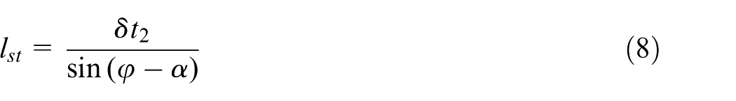
where
In accordance with Figure 10, the sticky length in the tool–chip contact zone decreased when ultrasonic vibrations exerted in the cutting process.
Conclusion
In this study, a two-dimensional FE model has been developed to simulate the periodic cutting process of UAT. In addition, a series of experimental tests were conducted to validate the simulation results. A flat-faced cemented carbide insert was used to turn AISI 304 stainless steel. Furthermore, a pneumatic QSD and a VMM were used in the experiments. The main conclusions are listed below:
Comparison of shear angle shows predicted and experimental values are in good agreement.
Shear angle increases when ultrasonic vibration is added to the cutting tool.
Increase in shear angle decreases sticky length in the tool–chip contact zone.
Increase in cutting speed results in an increase in tool–chip engagement time.
The average value of cutting force is significantly lower in vibration cutting compared to conventional one.
The results show that a direct relation exists between maximum linear vibration of cutting tool with sticky region and temperature on the tool rake face.
The harmonic movement of cutting tool causes a decrease in temperature in the tool–chip contact zone.
Consequently, lower temperature on the tool rake face coupled with higher shear angle in UAT causes the sticky region in tool–chip interface to be reduced compared to CT.
Footnotes
Declaration of conflicting interests
The author(s) declared no potential conflicts of interest with respect to the research, authorship, and/or publication of this article.
Funding
The author(s) disclosed receipt of the following financial support for the research, authorship, and/or publication of this article: Financial and technical supports were provided by the Production Lab of University of Kashan.