
Abstract
The study of residual stresses induced during machining is of considerable importance due to their effect on fatigue life of machined components. The metallurgical changes occurred due to thermo-mechanical phenomenon in cutting process affects the distribution of residual stress in machined components. Ultrasonic vibration assisted turning (UVAT) is effective machining process for low thermal conductivity materials like Ti6Al4V alloy and improves the surface characteristics by reducing cutting force and cutting temperature. In this paper, experimental and finite element (FE) studies are conducted to study the circumferential and axial residual stress distribution in UVAT of Ti6Al4V alloy. FE model is developed to study the effect of vibrating parameter (ultrasonic power intensity) and cutting parameters (cutting speed, feed rate, and depth of cut) on the residual stress profiles of machined surface. The FE simulation results of cutting force and cutting temperature are validated with experimental results. The circumferential and axial surface residual stresses obtained from FE simulation are also compared with experimental results using X-ray diffraction method. The effect of thermo-mechanical loading on residual stress distribution is analyzed with respect to force components (cutting force and feed force) and cutting temperature. Finally, the effect of each cutting parameter on subsurface layer of machined component is analyzed.
Keywords
Introduction
Surface integrity is the most influential parameter for quality and performance of the machined components. Surface integrity of components depends on thermo-mechanical loading induced during machining process. Machining induced residual stress is one of the significant factors used for evaluating surface integrity of machined component. These residual stresses have considerable effect on life of components by influencing its corrosion resistance and fatigue strength. 1 Residual stresses can be either tensile (positive) which deteriorate the life of components by initiating crack propagation or compressive (negative) which improve its mechanical properties. 2 The state of residual stress induced during machining process not only depends on cutting conditions but also on the material used.
Ti6Al4V (Ti-alloy) is increasingly used in aviation and bio-medical fields due to its high strength to weight ratio, high toughness, and superior corrosion resistance. 3 The high chemical reactivity and low thermal conductivity decreases the machinability of Ti-alloy.4,5 At high cutting temperature, these alloys adhere to cutting edge of the tool and alloy particles act as abrasives which further reduces the life of the tool. 6 Furthermore, the cutting tool edge radius plays a critical role and it must have finite edge radius in cutting tools. The larger edge radius tools reduce the chipping of cutting edge by improving its cutting edge strength. However, larger edge radius tools damages the subsurface of machined component by inducing larger strains. 7 Moreover, resharpening of cutting tool with oscillating mechanism can be used to enhance the life of the tool by improving surface profiles. 8 The machinability of Ti-alloy also depends on the cutting parameters used for machining. The increased thermal gradient with increase in cutting speed (V), feed rate (fr), and depth of cut (DOC) promotes the phase transformation of machined surface, which reduces the machinability of Ti-alloy. Hence, it is required to use lower cutting conditions or any advanced machining techniques to improve machinability.
The thermo-mechanical phenomenon occurred during cutting process is the main source for the generation of residual stresses during machining process. 9 The increase in thermal load due to increase in temperature is the source for generation of positive residual stresses. The machined surface is subjected to phase transformation due to heat produced by plastic deformation and frictional heating. The volumetric change of material generates either tensile or compressive residual stresses due to phase transformation. But, it is difficult to estimate the importance of each of these factors in generation of residual stresses. The combined effect of thermo-mechanical loading and phase transformation decides the state of residual stress in components. Hence, the final stress state of material also depends on the machining parameters used in machining process. 10
Several researchers have been used both experimental and numerical methods to evaluate the significance of machining parameters on residual stress distribution. Outeiro et al. 11 analyzed the effect of thermo-mechanical phenomenon on residual stress distribution in machining of Inconel 718 and stated that these stresses were mainly due to the heterogeneous plastic deformation caused by the cutting forces and the effect of thermal load was negligible. It is commonly admitted that severe plastic deformation and large heat generation during machining process develops compressive and tensile nature of residual stresses respectively. From the literature, it is evident that non-uniform heating, heterogeneous plastic deformation and dissimilar chemical composition are the reasons for generating residual stresses during machining process. Copello 12 observed that tool tip radius and feed rate have significant effect on distribution of residual stress whereas rake angle and cutting speed have negligible effect. Arrazola et al. 13 analyzed the effect of cutting parameters on residual stress distribution in machining of Inconel 718 using 3D FE model. They reported that tensile residual stresses were increased with increase in heat generation. Xin et al. 14 attested from their experimental study that subsurface layers of machined component were also affected during machining of Ti-alloy.
From above literature, it is identified that thermo-mechanical loading occurred during cutting process is the reason for formation of residual stresses. Hence, it is important to identify the parameters which affect heat generation and mechanical loading which eventually affect the residual stresses. Moreover, machining of Ti-alloy at high speed machining subjected to larger strain and strain rates on machined surface which generates larger heat during cutting process. 15 There are so many techniques to reduce the heat and mechanical force in cutting process. Ultrasonic vibration assisted turning (UVAT) is an important manufacturing process in which cutting tool is continuously excited with high ultrasonic frequency and low amplitude.16–18 The intermittent cutting action between tool and workpiece in UVAT process reduce the generation of heat and mechanical load that results in improved state of residual stress.19,20 Hu et al. 21 analyzed the performance comparison between ultrasonic-assisted ultra- precision turning (UAUT) and conventional ultra-precision turning (CUT) in machining of Ti6Al4V alloy. They reported that ultrasonic vibration has a great influence on reduction of cutting force, cutting temperature, and residual stresses in UAUT compared to CUT. Celaya et al. 22 observed the effect of direction of vibrations in UVAT of 1045 steel. It was reported that the vibration applied in cutting direction improved more surface finish (40%) than vibration applied in feed direction (6%). In machining of Ti-alloy, the performance of UVAT was improved with high frequency (f) and amplitude (a) at low cutting speeds.23,24 Nath and Rahman 25 proved that cutting speed, ultrasonic frequency, and amplitude were the only parameters effecting the performance of UVAT and reported that significant improvement was observed at lower cutting conditions. Maurotto et al. 26 reported substantial improvement in surface finish with newly developed UVAT system compared to CT in machining of Ti-alloy.
The mechanism of residual stress distribution in UVAT was studied by few authors. Ying et al. 27 developed a theoretical prediction model to estimate machining induced residual stresses in longitudinal-torsional ultrasonic vibration milling (LTUM) process. They observed that the higher mechanical stress and the lower thermal stress in LTUM process generates compressive residual stresses on surface and subsurface layers of machined surface. Nestler and Schubert 28 studied the residual tress distribution in UVAT process by imparting vibration in cutting, radial and feed direction. It was identified that negative residual stresses were observed on surface of the workpiece when vibrations imparted in cutting and radial direction. Maroju and Pasam 29 conducted numerical analysis to understand the dynamic changes in residual stress distribution in various stages of UVAT during Ti-alloy machining and results were compared with CT. It was identified that variation of compressive residual stresses was significant in the direction of vibration. Sharma and Pandey 30 developed an optimization model to evaluate the significance of cutting and vibrating parameters for minimization of surface residual stresses. This study reported that ultrasonic power intensity (Pu) plays a major role in minimization of surface residual stresses. From above literature, it is observed that the studies on thermo-mechanical phenomenon on residual stress distribution in UVAT of Ti6Al4V alloy are not fully understood. Furthermore, there is an ambiguity among researcher on distribution of residual stresses with machining parameters in UVAT process.
The present research work aims to evaluate the influence of machining parameters on thermo-mechanical phenomenon which eventually effects residual stress distribution in UVAT of Ti6Al4V. The Johnson-Cook (JC) parameters determined from machining based approach which consider the thermo-mechanical phenomenon is used in development of FE model for the evaluation of residual stresses. The developed FE model is used to understand the dynamic effect of ultrasonic vibration on residual stress distribution and it is validated with experimental results. The effect of separation between tool and workpiece on residual stress distribution is also evaluated at various stages of UVAT process. Furthermore, force components and cutting temperature obtained from experimentation are analyzed at various cutting conditions to understand the thermo-mechanical phenomenon in UVAT process. The developed FE model is used to analyze residual stress depth profiles in circumferential and axial direction with respect to thermo-mechanical phenomenon at various machining conditions.
Materials and methods
In the present work, Ti6Al4V workpiece of 40 mm diameter and 220 mm length was considered and cutting length of 20 mm was used for each experiment. In order to ensure stress free, Ti6Al4V workpiece was annealed at 590°C for 2 h and followed by furnace cooling before experimentation.
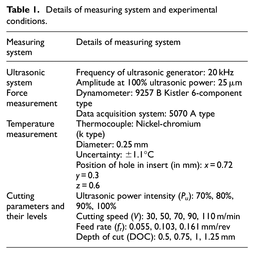
UVAT of Ti6Al4V experiments were conducted on precision lathe (Model:Magnum-2000) with ultrasonic system fixed on suitable fixture as shown in Figure 1. The cutting parameters and their levels considered for this study are shown in Table 1. For these experiments, cemented carbide type inserts (CNMG120408 THM) and Widia tool holders (PCLNR2525M12) were used. Each experiment was conducted with new cutting insert to avoid the effect of tool wear. The ultrasonic system used for this experiment consists of ultrasonic generator, piezoelectric transducer, booster, and horn. The ultrasonic generator with piezoelectric transducer was used to convert electrical energy into mechanical energy. The booster and cylindrical horn was used to amplify the displacement at the end of transducer. The ultrasonic vibrations at the end of horn were provided to cutting tool in cutting velocity direction (i.e. tangential direction) as shown in Figure 1(d). The change in amplitude was obtained by varying ultrasonic power intensity as these two parameters are in direct relation. 30 The digital vibrometer was used to calibrate the position of ultrasonic vibration system at various ultrasonic powers. The magnetic probe of vibrometer was attached to cutting tool to get the amplitude of ultrasonic system in UVAT process. Kistler six component dynamometer was used for measuring cutting force components and embedded thermocouple system was used for measurement of cutting temperature. The position of thermocouple in insert is shown in Figure 2. The details of UVAT measuring system and cutting conditions are given in Table 1.
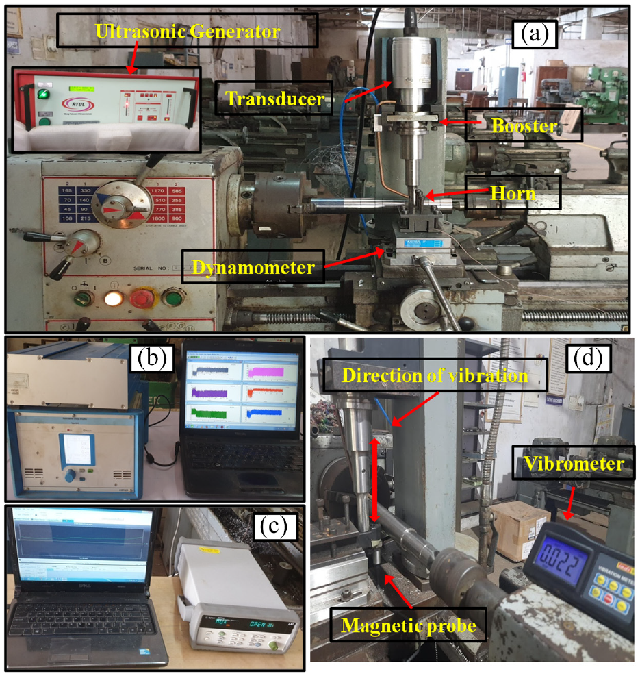
Experimental details: (a) UVAT setup, (b) force measuring system, (c) temperature measuring system, and (d) calibration of UVAT system.
Details of measuring system and experimental conditions.
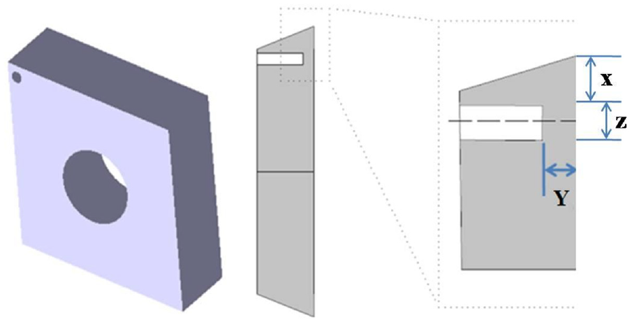
Position of hole in insert for embedded thermocouple system.
The change in interatomic spacing (d-spacing) occurred when material subjected to thermo-mechanical loading due to induced elastic strains. The residual stress state of machined component was obtained by X-ray diffraction (XRD) technique using a d versus sin 2 ψ method. 31 This method was used to obtain strain tensor from interatomic spacing changes of the material structure. An X-ray beam perfectly parallel and monochromatic was incident on sample and diffracted at different angles as shown in Figure 3. The residual stress state in a sample was obtained by using stress-strain relation from equations (1) and (2). Panalytical X’pert pro MRD with X’pert stress software was used to measure the residual stress profiles
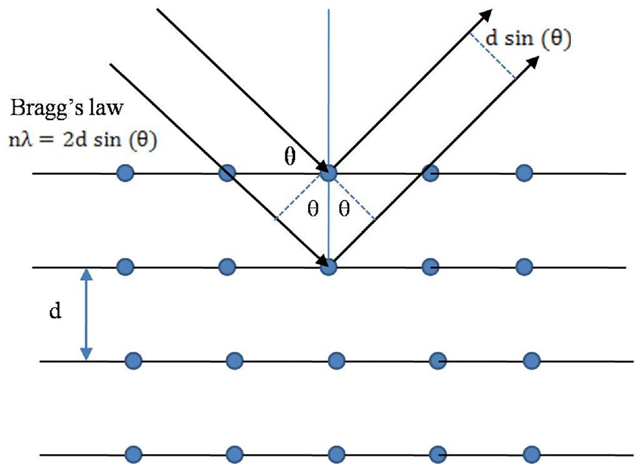
Representation of residual stress measurement law.
Cu-Kα material was selected for X-ray radiation and XRD system was calibrated with stress free sample. From phase analysis, it is determined that diffraction peaks for the un-machined and machined sample were obtained at 128° and 136° respectively. The mathematical equations used for calculating residual stresses form XRD technique are given below. 32
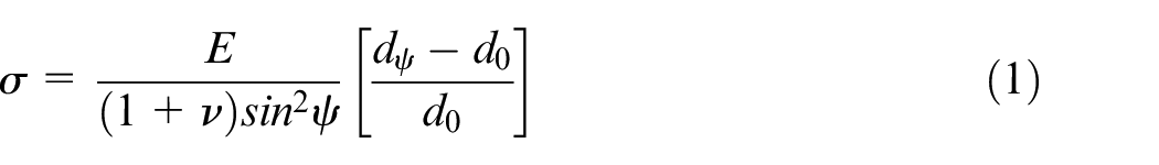
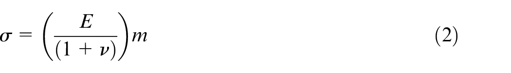
where E and
As the residual stress is sensitive to thermo-mechanical loading, the sample (10 mm × 10 mm × 5 mm) for measurement were cut from wire EDM process from cylindrical machined component. The machined sample was polished each time with a step of 15 μm up to 110 μm using electro polishing technique for measuring depth residual stress profiles.
Finite element (FE) modeling and simulation of UVAT process
A 3D FE model developed in ABAQUS with updated Lagrangian approach is used to analyze UVAT of Ti6Al4V alloy. 33 The workpiece is assumed as an isotropic material and Tungsten carbide (WC) cutting tool is assumed as a rigid to reduce the total simulation time. Coupled temperature-displacement of Hex-dominated (C3D8RT) element which facilitates both thermo-mechanical loading is selected with maximum elemental growth with higher accuracy. From mesh sensitivity analysis, optimized model is observed with 22,780 elements of workpiece and 6420 elements of cutting tool with rake and clearance angles. The simulations are performed with plane strain assumption as this is orthogonal machining process. The results are noted at near steady state condition. In this study, rigid tool is provided with vibrations and workpiece is assigned with cutting speed in x-direction for UVAT process. The relative displacement between tool and workpiece and boundary conditions used in simulation of UVAT as shown in Figure 4. The relative displacement of tool in UVAT process is given by an equation (3).

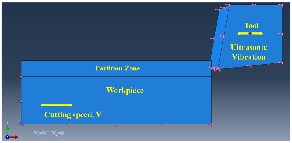
Relative motion and boundary conditions of tool and workpiece in FE simulation of UVAT.
where
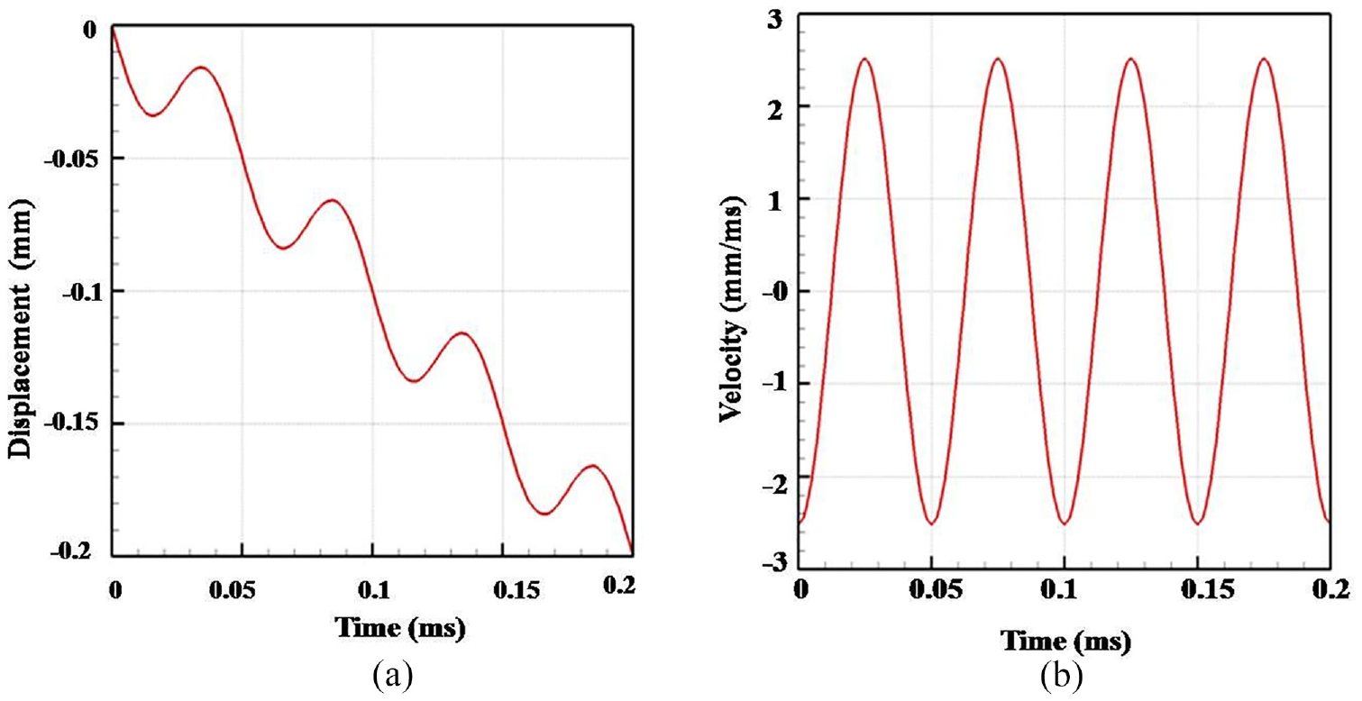
FE simulation of UVAT: (a) displacement and (b) velocity of cutting tool.
Material constitutive model
The constitutive material model used in FE model depicts the real physical behavior of the material during orthogonal machining. Furthermore, the accuracy of simulation results with experimental results mainly depends on material model used in FE simulation. Johnson-Cook (JC) material model is widely used in machining simulations and it is expressed equivalent flow stress in terms of strain (ε) term, strain rate (
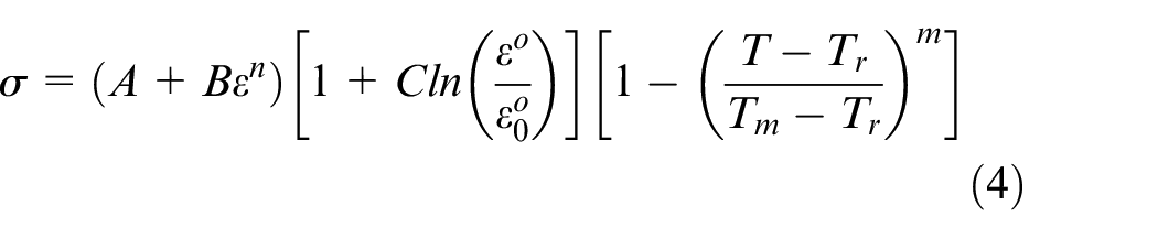
where
The deformation behavior of material during cutting process depends on the JC parameters used in the material model. However, different JC parameters are available for same material in literature. In this analysis, the JC parameters determined from machining based approach which consider the thermo-mechanical phenomenon at both primary and secondary deformation zones is used. 34 Hence, results obtain from this FE model could be more reliable than other models.
Separation criteria and damage equation
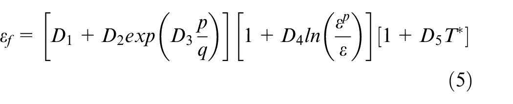
In these FE simulations, JC failure model 35 is used to predict the fracture initiation and its propagation during chip formation in orthogonal machining. The strain rate and stress tri-axiality effects are considered in JC failure model for accurate prediction of fracture during chip formation in orthogonal cutting and it is given by an equation (5).
where,
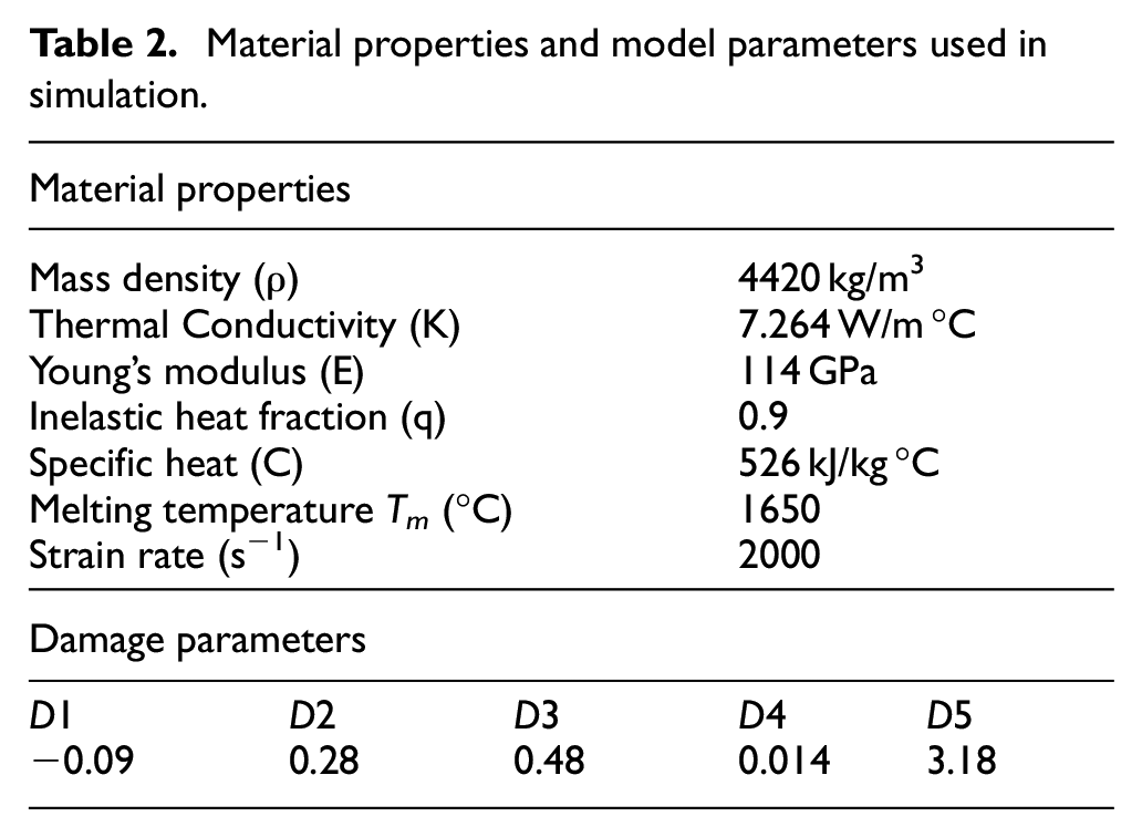
Material properties and model parameters used in simulation.
Residual stresses in UVAT process
The analysis of residual stresses developed during machining process through experimentation is costlier and time consuming. FE modeling is one of the powerful tool available to analyze residual stresses completely. In developed FE model, residual stress along the tangential direction that is, Circumferential residual stress (CRS) is S11 and perpendicular to cutting direction that is, Axial residual stress (ARS) is S33 as shown in Figure 6. FE simulation results are used to study the effect of machining parameters on CRS and ARS in UVAT process. As the residual stresses is dynamic in nature in UVAT, the average residual stress is evaluated by considering residual stress at three equidistant sections as shown in Figure 6.
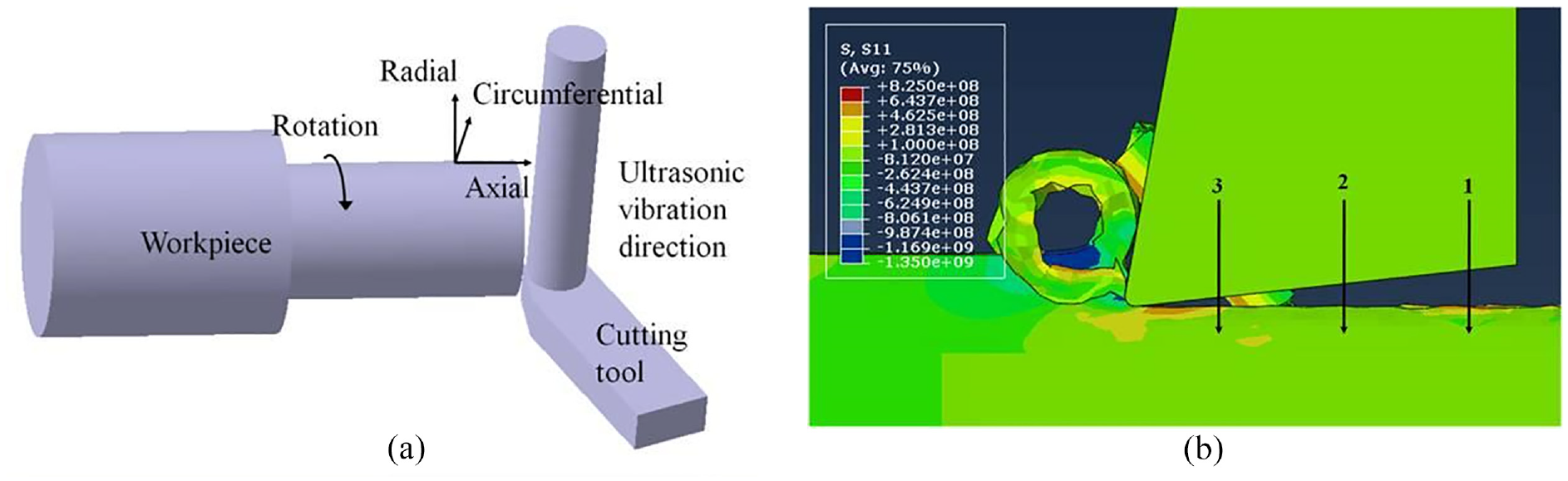
FE simulation of UVAT process: (a) directions of residual stress state and (b) measurement of residual stresses.
The residual stress distribution in UVAT process is analyzed in four stages for each cycle of vibration and its variation is shown in Figures 7 and 8. The FE simulations for this analysis are conducted at V = 30 m/min, fr = 0.055 mm/rev, DOC = 0.5 mm, and Pu = 100%. In stage I, average residual stress observed is 425 MPa (tensile) when cutting tool contacts the chip and its nature changes to compressive at a depth of approximately 50 μm. In second stage, tensile residual stresses are observed at each section and maximum observed on surface is 580 MPa when cutting tool penetrates into workpiece. The maximum plastic deformation of material occurs in this stage and thermal loading resulted from plastic deformation causes tensile CRS at this stage. In stage III, average tensile residual stress on surface is 260 MPa and its nature changes to compressive at a depth of 35 μm as the tool retracts from workpiece. In stage IV, an average residual stress on surface is 192 MPa (tensile) when tool is about to start for next cycle and its nature changes to compressive at a depth of 20 μm.
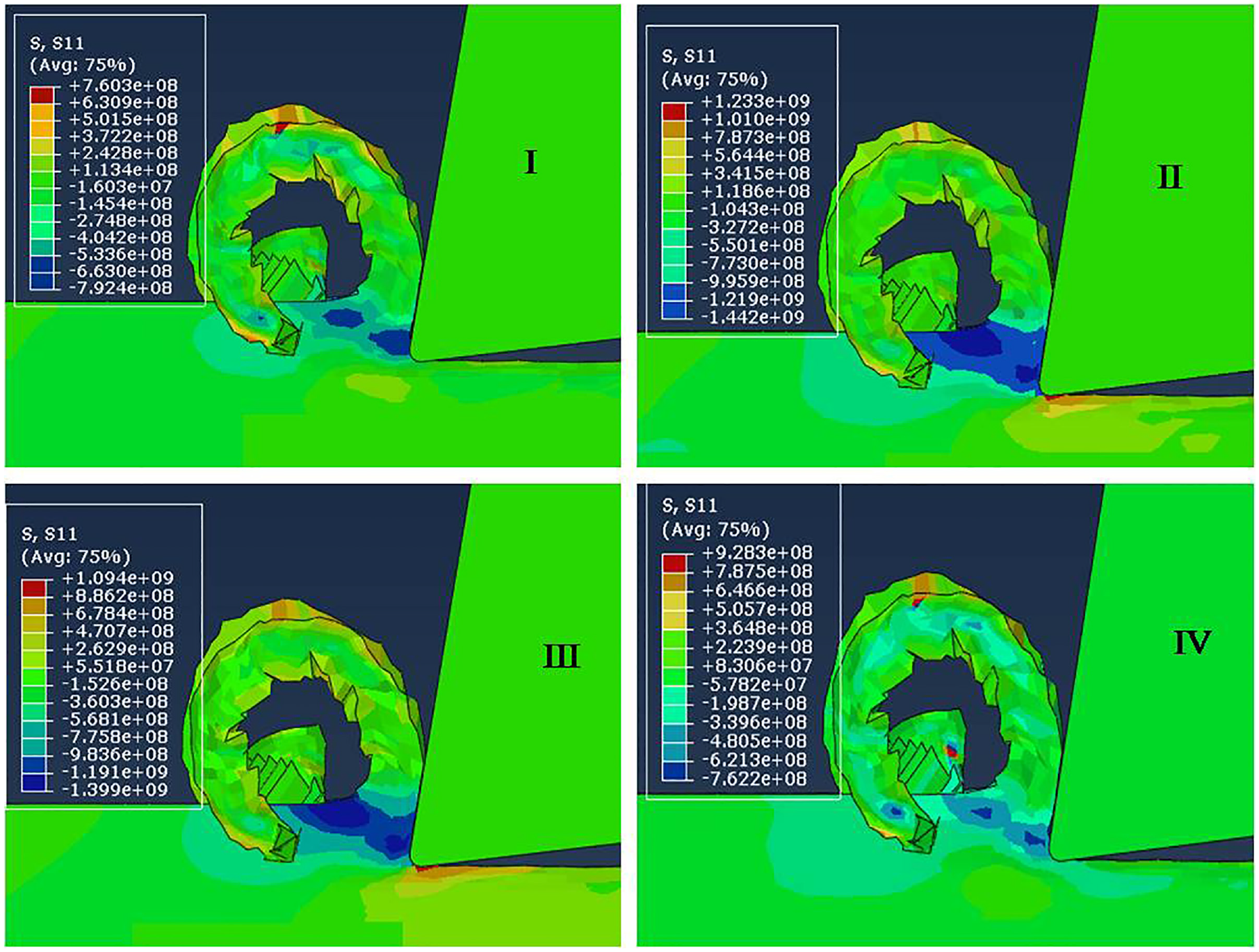
Residual stress distribution in various stages of UVAT process.
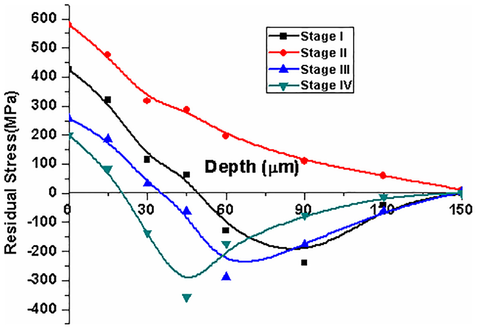
Depth profile of residual stress in various stages of one UVAT cycle.
Model validation
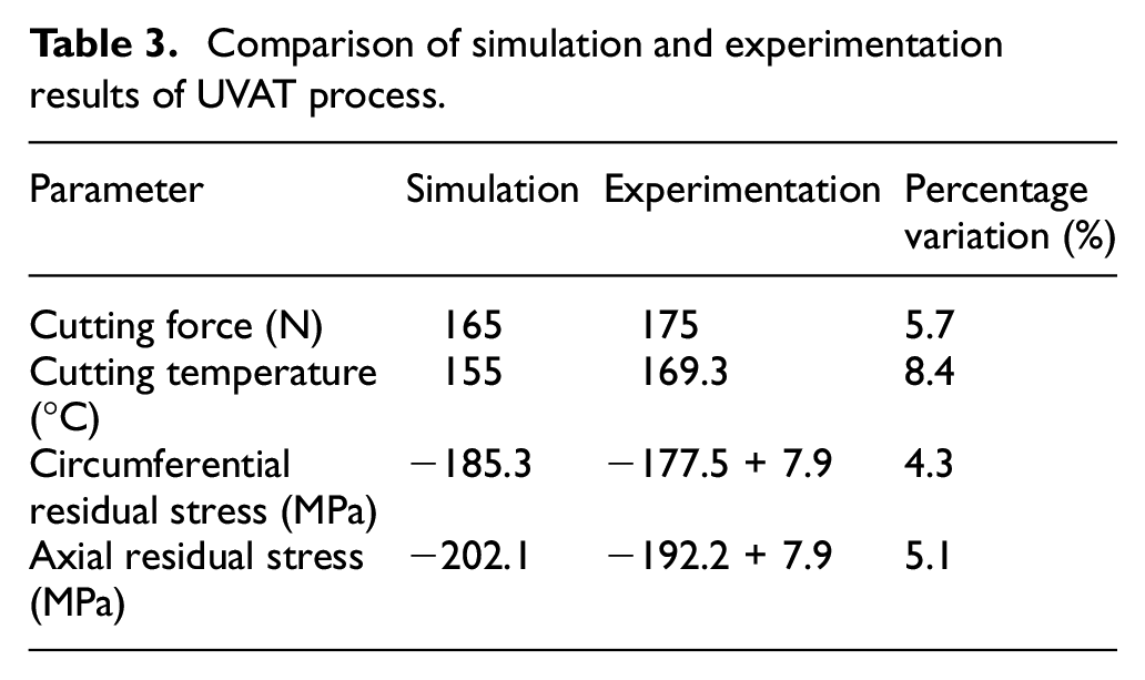
The developed FE model for UVAT process is validated with experimental results at 30 m/min of V, 0.103 m/min of fr, 0.5 mm of DOC, and 100% of Pu. The comparison between FE and experimental results of cutting force and residual stresses are shown in Figures 9 and 10. The percentage variation of cutting force and cutting temperature between simulation and experimental results are within the permissible limit. In order to validate the same FE model with respect to residual stresses, CRS and ARS obtained from simulation results on the surface are compared with experimental results at the same cutting conditions. However, the surface residual stresses obtained from simulation are dynamic in nature; hence the average residual stress obtained from simulation is compared with constant residual stresses obtained from experimentation. The variation between simulation and experimental results are within permissible limit as shown in Table 3. Hence, the developed FE model is used for further analysis of residual stress along the depth at various machining conditions. The interaction between chip and cutting tool in UVAT is difficult to evaluate due to dynamic effect of ultrasonic vibration. Probably, this could be the reason for having error between simulation and experimental results.
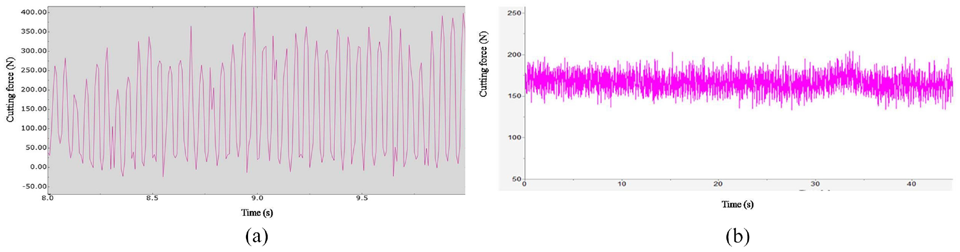
Cutting force comparison between: (a) simulation and (b) experimental results.
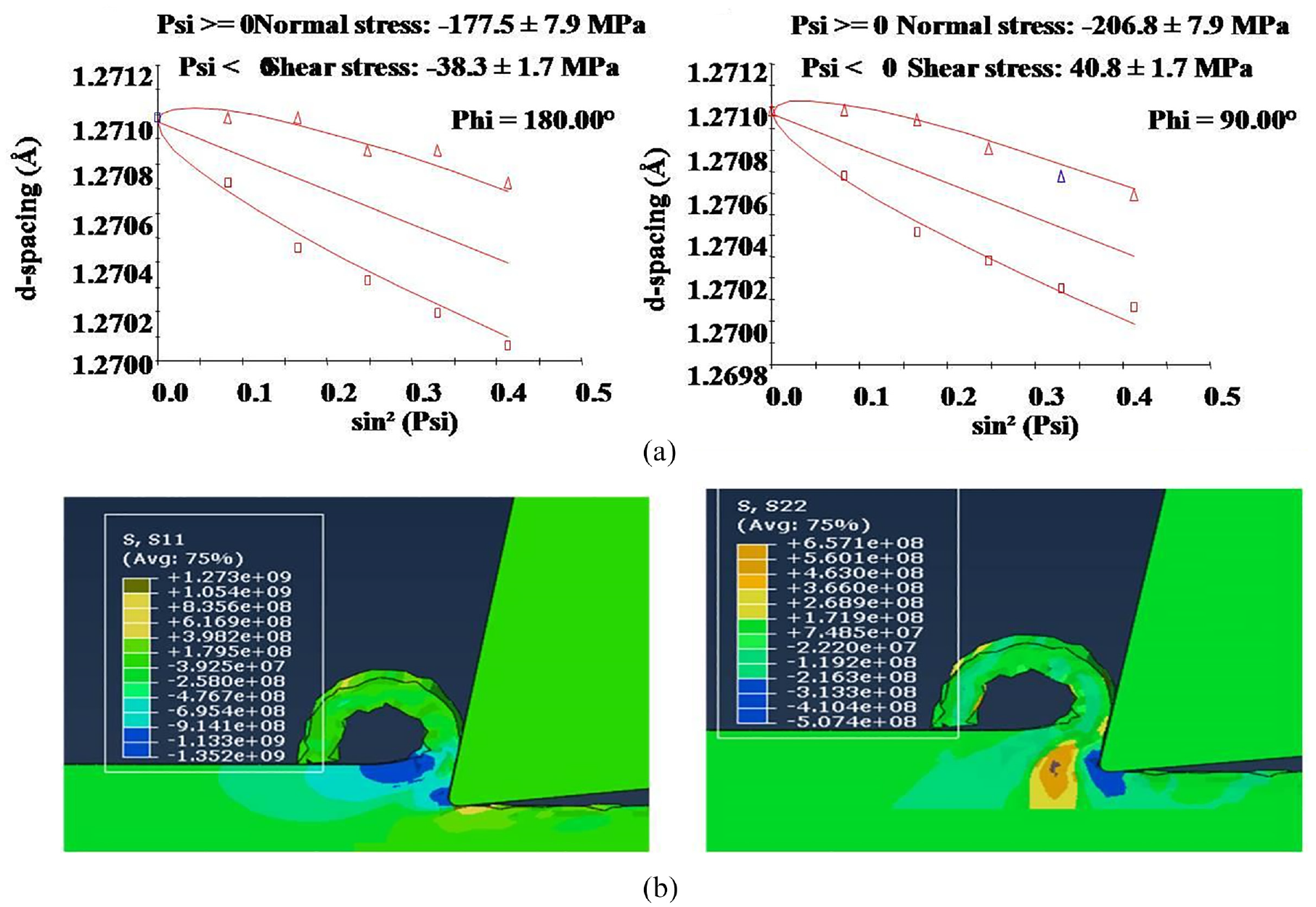
Residual stress comparison between: (a) experimental and (b) simulation results.
Comparison of simulation and experimentation results of UVAT process.
Results and discussion
In this section, the machining parameters effect on residual stresses is analyzed with respect to thermo-mechanical loading in UVAT process. 36 The thermo-mechanical aspects in UVAT process are analyzed by force components and cutting temperature from experimentation. Furthermore, residual stress distribution of machined components is analyzed with respect to thermo-mechanical phenomenon at same cutting conditions.
Effect of machining parameters on thermo-mechanical loading
The level of machining induced residual stresses are directly affected by heat generated due to plastic deformation and friction between chip and cutting tool.37,38 In order to describe the effect of thermo-mechanical loading on residual stress formation during UVAT of Ti6Al4V alloy, the force components (Fc and Ff) and cutting temperature are analyzed by conducting experiments at various cutting conditions where residual stresses are analyzed and the results are shown in Figure 11. The level of machining induced residual stresses are directly affected by heat generated due to movement of chip along rake face of the tool and plastic deformation. 37
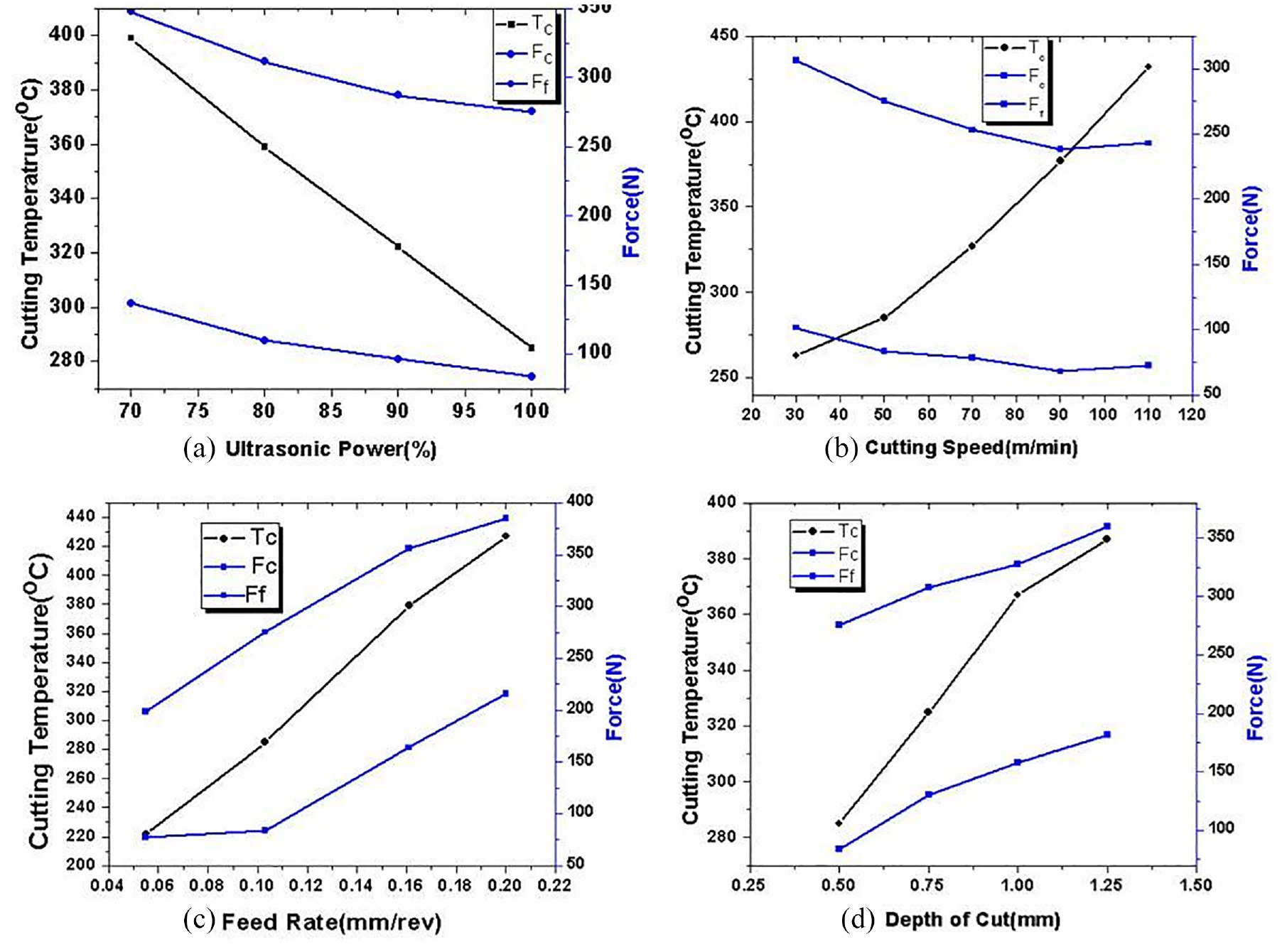
Evolution of cutting force and cutting temperature with machining regime of (a) Ultrasonic power (b) Cutting speed (c) Feed rate.
The type of residual stress and its affect on subsurface layer of machined components depends on thermo-mechanical loading in cutting process. From Figure 11(a), it is found that the force components and Tc are decreased with increase in Pu from 70% to 100%. The reduction in Fc and Ff with increase in Pu is mainly due to fracture dynamics of UVAT process. 39 The intermittent cutting action between tool and workpiece generate high impact energy per each cycle of vibration. This impact energy produces high stress wave velocity which affects the ultimate strength of chip before cutting action between tool and workpiece in UVAT process. Furthermore, the intermittent cutting action in UVAT reduce the larger strains produced on the machined surface which results in reduction of heat due to severe plastic deformation compared to CT. 40 Moreover, the yield strength of the material decreases with increase in thermal softening which leads to separation of chip from cutting zone with low cutting force. The increased separation between tool and workpiece with increase in Pu reduces the cutting time and increases the aerodynamic cooling during machining process. Hence, the reduction in thermo-mechanical load with increase in ultrasonic power significantly influences the distribution of residual stress. From Figure 11(b), it is found that Fc and Ff are decreased due to increase in thermal softening and Tc is increased due to adiabatic temperature zones with increase in V from 30 to 110 m/min in UVAT. The variation of thermo-mechanical loads due to increase in cutting speed also plays a major role residual stress distribution.
The variation of force components and cutting temperature at different fr and DOC is shown in Figure 11(c) and (d). The increased resistance to movement of cutting tool with increase in fr and DOC increases force components and cutting temperature. The increased thermo-mechanical load due to increase in f and DOC affects the residual stress generation in machining process. Hence, it is important to evaluate the variation of residual stresses on the machined surface and subsurface layer with variation of cutting conditions.
Influence of machining conditions on residual stress distribution
Influence of ultrasonic power
The influence of ultrasonic power on surface residual stress in UVAT process is analyzed at V = 50 m/min, fr = 0.103 mm/rev, and DOC = 0.5 mm. From Figure 12(a), it is observed that the surface CRS is changed from 50 MPa (tensile) to 28 MPa (compressive) when ultrasonic power is increased from 70% to 100%. Similarly, the surface ARS is changed from 125 MPa (compressive) to 221 MPa (compressive) for the same range of ultrasonic power. The state of residual stress on surface depends on dominance of either thermal or mechanical load. The dominance of thermal load over mechanical load is decreased with increase in ultrasonic power which results surface CRS is changed from tensile to compressive. However, compressive nature of surface ARS is increased with increase in ultrasonic power due to effect of thermal load in axial direction is negligible compared to mechanical load.
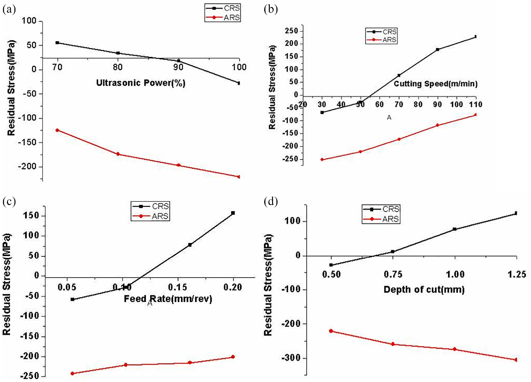
Evolution of surface residual stresses with respect to: (a) ultrasonic power intensity, (b) cutting speed, (c) feed rate, and (d) depth of cut.
Depth profiles of CRS and ARS are obtained at various ultrasonic powers as shown in Figure 13. From CRS distribution, it is observed that, the tensile layer thickness is decreased with increase in Pu from 70% to 90% and becomes zero at 100%. Similarly, the compressive layer thickness is increased with increase in Pu. The variation of residual stress depth profiles mainly depends on thermo-mechanical phenomenon involved in UVAT process. The reduction in thermal softening with increase in ultrasonic power decreases the impact of thermal load in generation of residual stress. And also, the reduction in cutting force indicates the decrease in mechanical loading effect with increase in ultrasonic power. However, the reduction in thermal loading is more significant compared to mechanical loading on CRS and hence, the magnitude of compressive CRS is increased with increase in Pu. However, the decreased mechanical load effects the maximum residual stress profiles. Hence, the maximum compressive stress is increased with increase in Pu. Similarly from ARS distribution, it is observed that, the maximum compressive stress is increased with increase in ultrasonic power due to reduction in thermal load. Moreover, the compressive layer thickness is increased with increase in Pu due to dominance of mechanical load.
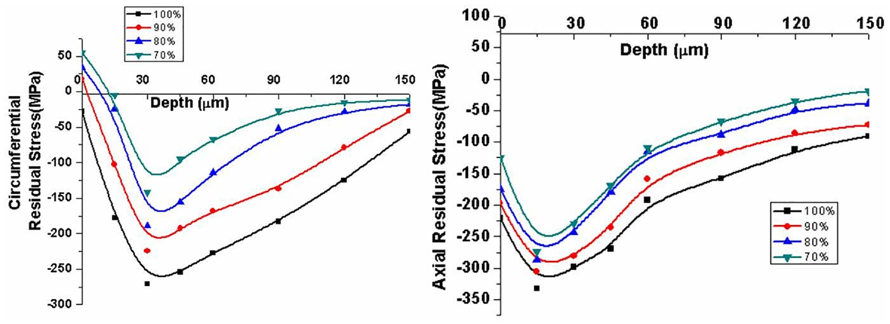
Evolution of CRS and ARS at different ultrasonic power intensity.
Influence of cutting speed
The influence of cutting speed (V) on surface residual stresses is analyzed at fr = 0.103 mm/rev, DOC = 0.5 mm, and Pu = 100% as shown in Figure 12(b). The surface CRS is changed from 68 MPa (compressive) to 228 MPa (tensile) when V is increased from 30 to 110 m/min. Similarly, the surface ARS is changed from 252 MPa (compressive) to 77 MPa (compressive) for the same range of V. The variation of both CRS and ARS on surface can be described with respect to force components (Fc and Ff) and cutting temperature. The decrease in Fc and Ff and increase in Tc with cutting speed increases the effect of thermal load over mechanical load in generation of residual stress. Hence, the surface CRS and ARS are increased with increase in V.
The influence of V on depth profiles of CRS and ARS are shown in Figure 14. From the depth profiles of CRS, it is observed that tensile layer thickness is increased and compressive layer thickness is decreased with increase in V. The increase in cutting temperature and decrease in force components (Fc and Ff) with increase in cutting speed induces more thermal load than mechanical load on the machined surface. This result in more heat effected layer of machined surface increases with increase in V. Hence, tensile layer thickness is increased. Moreover, the maximum compressive CRS is increased with decrease in V and its location is moves away from the surface. Similarly, the compressive layer thickness of ARS is increased with increase in V and maximum compressive ARS is also increased with cutting speed.
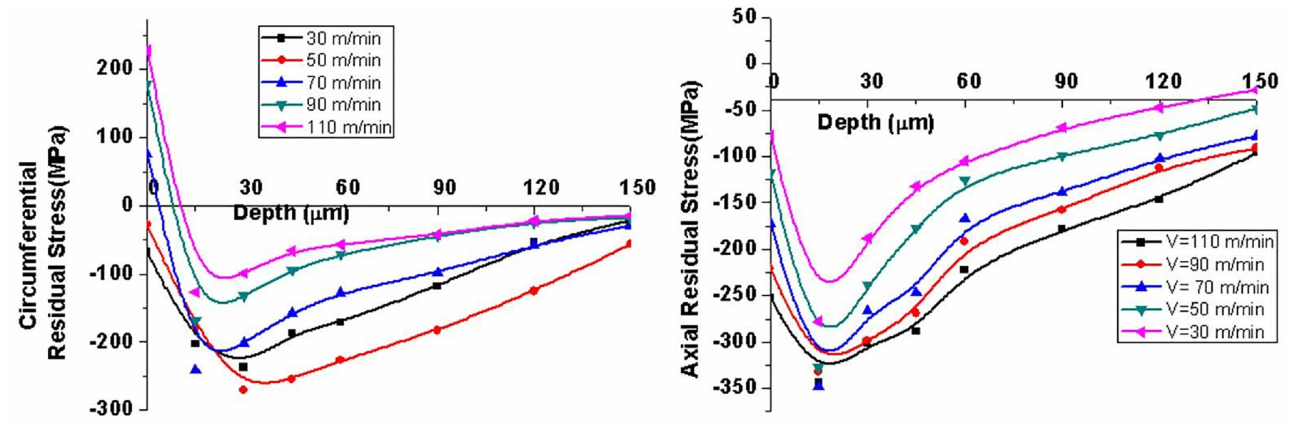
Evolution of CRS and ARS at different cutting speeds.
Influence of feed rate
The influence of fr on surface CRS and ARS is analyzed at V = 50 m/min, DOC = 0.5 mm, and Pu = 100%. From Figure 12(c), it is observed that the surface CRS is increased from 58 MPa (compressive) to 157 MPa (tensile) when fr is increased from 0.055 to 0.103 mm/rev. Similarly, surface ARS is changed from 242 MPa (compressive) to 201 MPa (compressive) with increase in fr. From the analysis, it is observed that the effect of fr on surface CRS is more compared to surface ARS. The increased force components (Fc and Ff) and cutting temperature with increase in fr induces more thermal load than mechanical load which results nature of surface CRS is changed from compressive to tensile. The nature of surface ARS is compressive due to negligible effect of thermal load compared to mechanical load. However, the effect of thermal load is increased with increase in fr which results in reduction of compressive surface ARS.
Depth profiles of residual stress along circumferential and longitudinal direction at various fr are shown in Figure 15. From CRS depth profiles, it is observed that tensile layer thickness is decreased with increase in fr and becomes zero for 0.2 mm/rev of fr. The compressive layer thickness and maximum compressive CRS is increased with fr and maximum compressive CRS location is shifted toward the surface. The resistance to movement of cutting tool induces large compressive region in primary deformation zone which is just below the cutting edge and influence the effect of mechanical load on generation of residual stresses. Similarly, from depth profiles of ARS, it is observed that the maximum compressive ARS is decreased with increase in fr and compressive layer thickness of ARS is not changed much with fr.
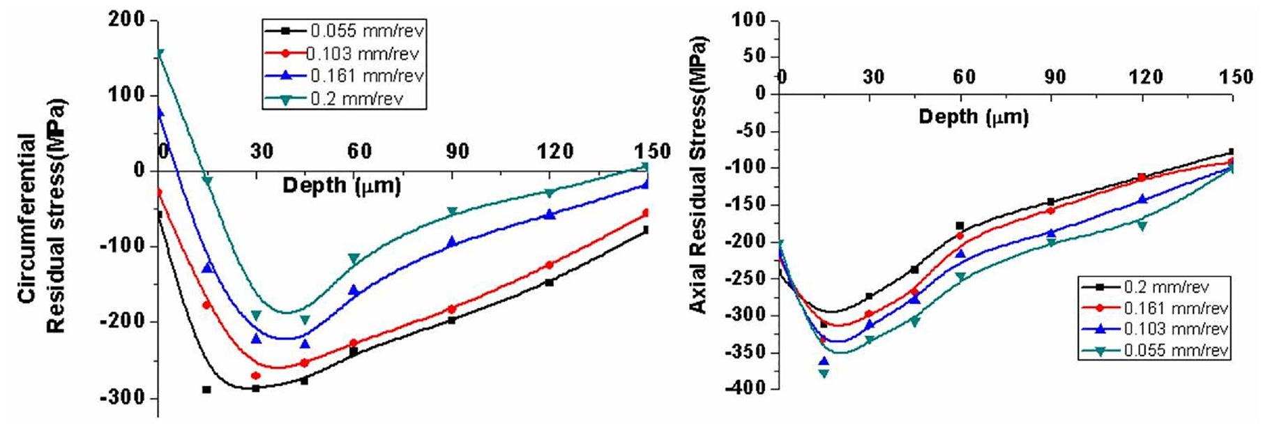
Evolution of CRS and ARS at different feed rates.
Influence of depth of cut
Influence of DOC on surface CRS and ARS is analyzed at V = 50 m/min, fr = 0.103 mm/rev, and Pu = 100%. From Figure 12(d), it is found that the surface CRS is increased from 28 MPa (compressive) to 124 MPa (tensile) with increase in DOC from 0.5 to 1.25 mm. The surface ARS is changed with increase in DOC from 221 MPa (compressive) to 305 MPa (compressive). The increase in force components (Fc and Ff) and cutting temperature with increase in DOC increases the thermal load on the surface which results in larger tensile surface CRS. The effect of DOC on surface ARS is less compared to CRS.
Depth profiles of CRS and ARS at various DOC are shown in Figure 16. From CRS depth profiles, it is observed that the tensile layer thickness is increased with increase in DOC whereas compressive layer thickness is decreased with same DOC conditions. Moreover, the maximum compressive CRS is also decreased with increase in DOC. The increased heat generation with increase in DOC affects the subsurface layer which results in tensile CRS are formed in subsurface layers. Similarly, from depth profiles of ARS it is found that the compressive layer thickness is decreased and maximum compressive ARS is increased with increase in DOC.
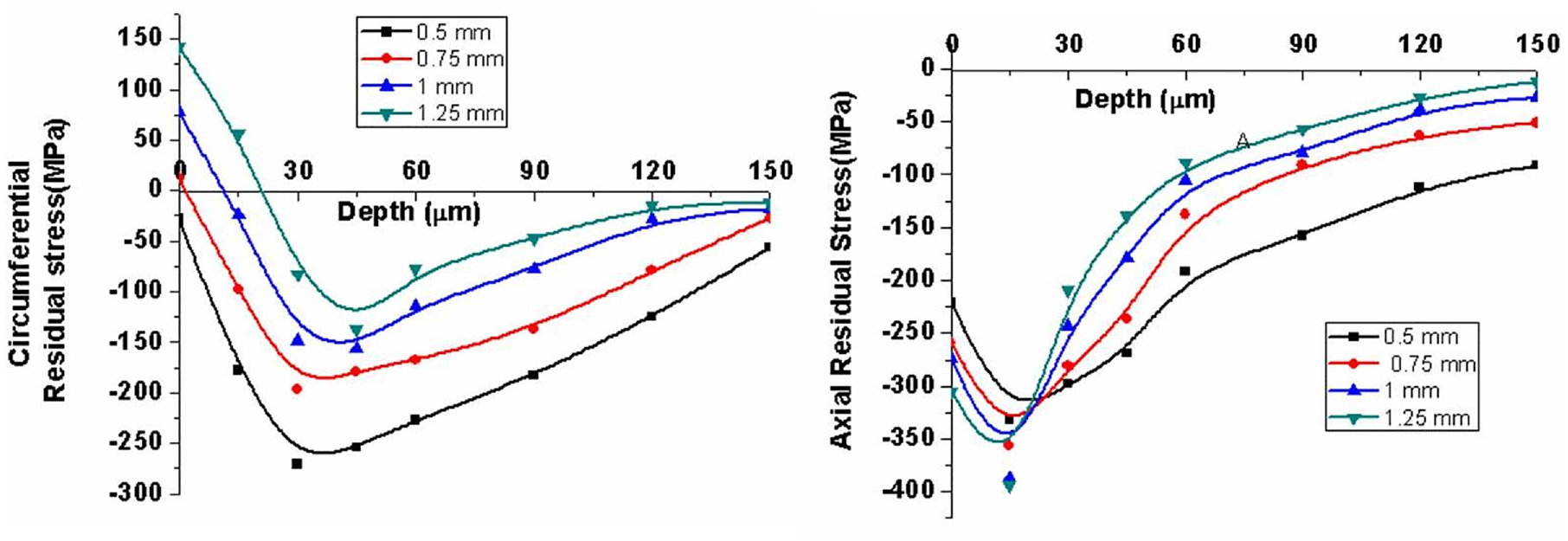
Evolution of CRS and ARS at different depth of cuts.
Interaction effects
From above discussion, it is observed that the variation of CRS and ARS with each machining parameter depends on the thermo-mechanical phenomenon occurs during cutting process. The contact time between tool and workpiece decides the thermo-mechanical loading in UVAT method. From the fundamentals of simple harmonic motion, it is identified that f, a, and V are the three important cutting parameters which effect the contact time in UVAT process. 41 The interaction effects of vibrating parameter that is, ultrasonic power with machining parameters such as V, fr, and DOC are discussed in this section.
Interaction between ultrasonic power and cutting velocity
The time of contact between tool and workpiece is rapidly increased at lower and higher cutting speeds whereas moderately increased at medium cutting speeds. However, the time of contact is decreased with increase in Pu. The decreased time of contact promotes better aerodynamic lubrication which results in increased heat removal from the surface in UVAT. Hence, the mechanical load dominates over the thermal load at higher ultrasonic power and moderate cutting speeds which generates the compressive residual stresses. Moreover, at constant ultrasonic power, shear angle is increased with increase in V which results in increased rate of heat conduction from chip to workpiece. This leads to the generation of tensile residual stress due to high thermal effect.
Interaction between ultrasonic power, feed rate, and depth of cut
The effect of fr and DOC are similar in cutting process with respect to thermo-mechanical phenomenon. The fr and DOC, and Pu have opposite trend in generation of residual stress. From Figure 11, it is observed that thermal effect is more at higher fr and DOC, and lower Pu which results in generation of tensile residual stress on machined surface. Hence, the advantage of intermittent cutting in UVAT process is predominant at higher ultrasonic power. Moreover, the rise in thermal effect enhances the ironing effect with increase in ultrasonic power which results in improved machined surface.
Conclusions
The results obtained in this work may be used to optimize the vibration and cutting parameters with an objective of maximum compressive residual stress. It is required to evaluate each parameter influence and then optimize the parameters with suitable optimization technique. The following conclusions are obtained from the present research work.
The tensile and compressive layer thickness of CRS and ARS are depends on contact time between tool and workpiece in all stages of one UVAT cycle.
The increased ultrasonic power intensity changes the surface CRS from tensile to compressive and the surface ARS from lower to higher compressive state. It is also found that the tensile layer thickness is decreased and compressive layer thickness is increased for CRS and ARS with increase in ultrasonic power.
Increased thermal load with increase in cutting speed from 30 to 110 m/min decreases the compressive layer thickness and increases the level of surface CRS and ARS.
Increased feed rate increases the compressive layer thickness and decreases the level of CRS and ARS due to dominance of mechanical load over thermal load. Similarly, compressive layer thickness and level of CRS and ARS are decreased with increase in depth of cut due to thermal dominance over mechanical load.
Footnotes
Declaration of conflicting interests
The author(s) declared no potential conflicts of interest with respect to the research, authorship, and/or publication of this article.
Funding
The author(s) disclosed receipt of the following financial support for the research, authorship, and/or publication of this article: The authors gratefully acknowledge, DST, INDIA for the financial support and TATA Sikorsky Aerospace Limited, Hyderabad, INDIA for the technical support provided for the present work (Project No: DST/TDT/AMT/2017/060/G).