
Abstract
The aim of this work is to fabricate the high-density polyethylene–copper composites by submerged friction stir processing at different traverse speeds. The scanning electron microscopy is used to analyze the distribution of microstructure and particles. The experimental results indicated that the macrostructure morphology, microstructure and tensile strength vary depending on the traverse speed. Compared with the pure high-density polyethylene, Cu-filled polymer composites showed lower tensile strength and higher microhardness. The maximal values of the tensile strength and microhardness were achieved at traverse speeds of 30 and 15 mm/min, respectively. The thermal properties of Cu-filled high-density polyethylene composites were studied by differential scanning calorimetry. The crystalline content of the composites was decreased due to the addition of copper. From the experimental tests, it can be concluded that submerged fiction stir processing has a great potential for producing polymer–metal composites.
Keywords
Introduction
Polymer composites have many desirable performances such as high strength and rigidity, excellent creep and wear resistance and low coefficient of thermal expansion.1,2 In recent years, polymer–metal composites have been widely used in many industries such as optoelectronics, electromagnetic absorbing materials and color filter because of their comprehensive properties of both metals and polymers.3,4 Several methods have been used to produce polymer matrix composites, such as high-energy ball milling, 5 mixing 6 and friction stir processing (FSP).7–10
FSP was developed as a novel method for modifying and processing new materials, which was based on the fundamental principles of friction stir welding (FSW).11–14 In the FSP process, a rotating tool with a special shoulder and pin slowly inserts into a monolithic workpiece until the shoulder contacts the workpiece surface. Under the heating generated by friction and material plastic deformation, the material is softened and plasticized. The materials are broken, mixed and undergo severe plastic deformation. 15 Ultimately, the microstructure of materials becomes dense, uniform and refined.
FSP technology has important implications for the production of polymer materials due to their high efficiency and environmentally friendly nature, although there are some other methods to prepare them. Although studies have been conducted on fabrication of the composites by FSP, almost all of them were about FSP of metals, and unfortunately, the research works on FSP of polymers are still limited. Barmouz et al. produced high-density polyethylene (HDPE)–clay nanocomposites using a novel method based on FSP in order to enhance the dispersion state of nanoclay particles and surface mechanical properties. The results showed that the microhardness of samples increased by 62%. They concluded that FSP had a tremendous potential for surface modification of polymeric materials. 7 Azarsa and Mostafapour 8 designed a novel tooling system which included a stationary shoulder, a rotating pin and a heating system located inside the shoulder to produce HDPE/copper using FSP. The research showed ultimate tensile strength, and the modulus of elasticity increased by 10% and 30%, respectively, at transverse speed of 60 mm/min and shoulder temperature of 110 °C, which was higher than the values observed in conventional methods. Zinati et al. manufactured polyamide–multiwalled carbon nanotube (MWCNT) nanocomposites via FSP to investigate the thermomechanical behavior of composites and built a numerical model based on Lagrangian incremental formulation. The results showed that the MWCNTs were dispersed while passing the tool-pin because of high plastic strain applied on them. Also, they found greater amount of the materials accumulated in the advancing side of the stirred region after passing the tool-pin. Meanwhile, the MWCNTs were straightly and homogeneously dispersed throughout polyamide 6 (PA6) and hence caused the performance boost.9,10 The present FSP of polymer materials was still under study in laboratory, but the reports look promising in fabricating polymer composites that have been studied. It had practical application value and scientific research significance in preparation of polymer composites or in extending the application of FSP technology. Particularly, it has great potential in terms of making polymer surface composite. In this case, the surface of the polymer material is compound with higher mechanical properties (e.g. hardness) without changing the bulk material. 9
Polymer material has a low thermal conductivity, a very short solidified time and a low melting temperature. In the process of polymer FSP, the friction heat mainly concentrated in the weld nugget, which resulted in excessive fusion of the materials of weld nugget. Meanwhile, the material flow in this process was difficult to control. In order to solve these problems, different methods had been used, including in-process using a special tooling system 8 and submerged friction stir processing (SFSP), which was a new variation of FSP. The SFSP took place under a specific ambient temperature. In the research about submerged FSP of metal materials, it has been found that the existence of the water not only decreases the peak temperature of stir zone but also effectively controls the thermal cycle of the weak part. 16
As the third largest commodity thermoplastic worldwide, HDPE had been extensively employed in industry because of its durable, inexpensive, chemically stable and easy-to-process nature. 9 But the weather resistance, toughness and environmental stress cracking resistance were too poor to apply in many high-technology areas. 17 Reinforcing HDPE with fillers had been found to improve its properties.18,19 The copper particle–reinforced HDPE has wide application in some engineering fields due its good mechanical, electrical and thermal properties. 3
In our previous study, we have fabricated HDPE–MWCNT composites via SFSP and found that it could improve the forming of processed zone and reduce the number of defects. 20 The aim of this study was to fabricate polymer–copper composites using FSP in water as well as in air and investigate the macrostructure, microstructure, mechanical properties and thermal properties of the composites. The possible interactions between copper particles with the HDPE matrix were investigated. The attempts were made to reveal the structure–property relationships on the basis of research results.
Materials and methods
HDPE was used as the matrix component. The copper powder used in this study had particle size <5 µm, with over 99.5% purity. Figure 1 shows the schematic of FSP Cu–HDPE composites. In order to produce HDPE–copper composite, first, some special Φ2.5 mm × 2.0 mm (diameter, depth) blind holes were processed in the middle of HDPE plate; second, the Cu particles were put and compressed in blind holes; finally, a 4-mm HDPE sheet was placed on the lower sheet in order to prevent Cu fillers from overflowing. The volume fraction of Cu was 4% which was estimated by dividing the amount of Cu in the holes and the area distributed in the matrix.
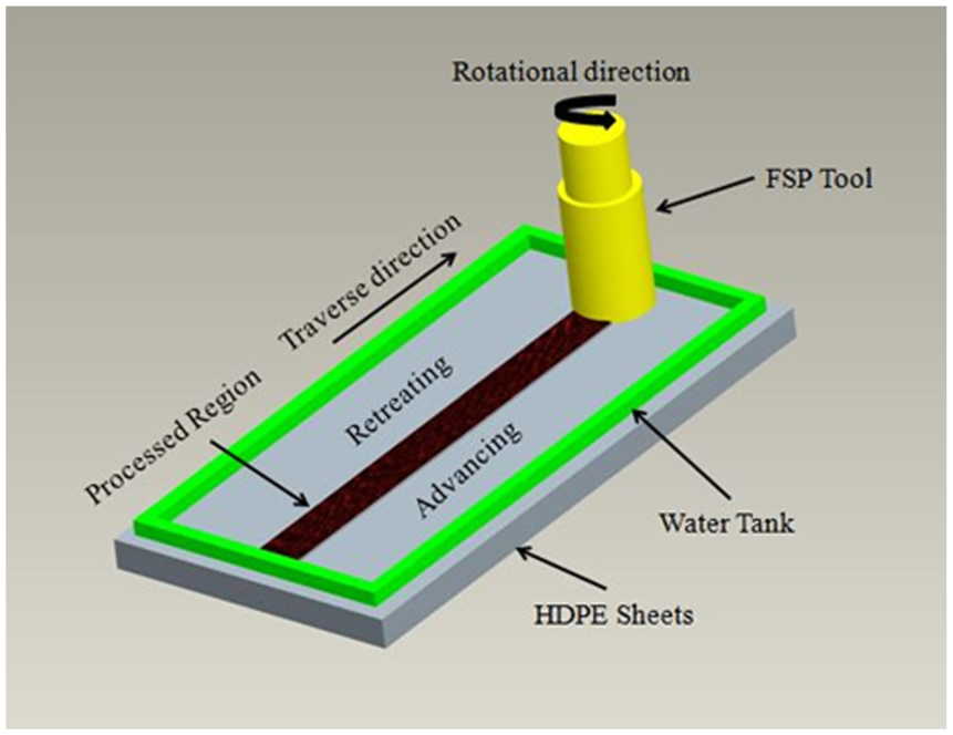
Schematic of submerged friction stir processing.
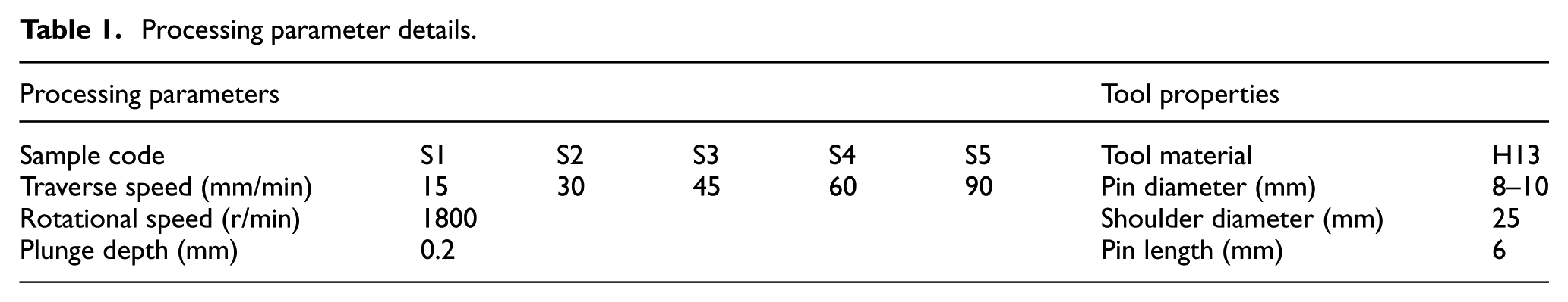
Figure 2 shows the distribution of blind holes and configuration applied in this study. The rotating tool used in this experiment is the tapered pin. Figure 3 shows the FSP tool schematic. A round pin was used because it can soften the materials adequately for good morphology and obtain better properties. 21 The tool and welding parameters are presented in Table 1.
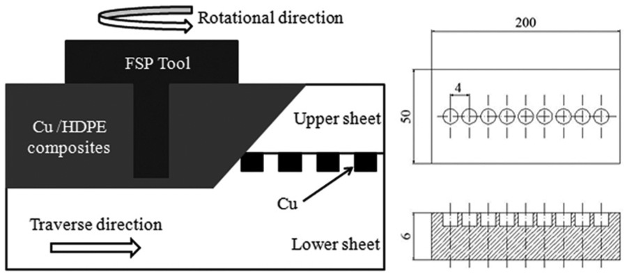
Schematic illustration of the distribution of blind holes and configuration applied in this study (dimensions in mm).
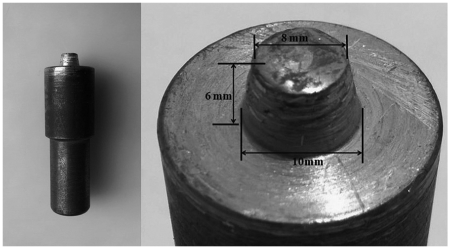
Friction stir processing tool.
Processing parameter details.
The tensile test was carried out on the CMT 5105 SANS microcomputer control electronic universal tensile testing machine at room temperature, according to the ASTM D638 standard. The strength was obtained by averaging the strengths of five individual specimens, which were processed under the same parameters.
The microhardness of the HDPE and composites was measured on the cross section of the processed zone and perpendicular to the traverse direction using an indenter with a 50-g load for 15 s on a HV-1000 Vickers microhardness tester. The standard Vickers microhardness (H) was determined by the equation 7
where P is the load, d is the average value of the diagonal length of the rhombus after unload and k is the geometric factor equal to 1.854. The experimental data were the average of 15 imprints under the same conditions.
For macrostructure research, a new cross section was cut from the welded specimen using a Leica RM2235 model rotary-type microtome. The microstructure of the specimens was studied using JSM-6360LV scanning electron microscopy (SEM). The SEM samples were fractured after freezing in liquid nitrogen. The fractured surfaces were coated with gold prior to observation.
The thermal behavior of the composites was analyzed by STA 409 PC differential scanning calorimetry (DSC). The heating rate of all specimens was 10 °C/min at 20 °C–550 °C. The experiment was conducted with N2 as a protective atmosphere, and the flow rate of N2 was 30 mL/min.
Results and discussion
Morphology analyses
The upper surfaces and cross sections of the FSP samples obtained at different traverse speeds are shown in Figures 4 and 5, respectively. It is important to note that Figures 4(a) and 5(a) showed the upper surfaces and cross sections of the conventional FSP sample at the traverse speed of 30 mm/min and rotational speed of 1800 r/min, respectively.
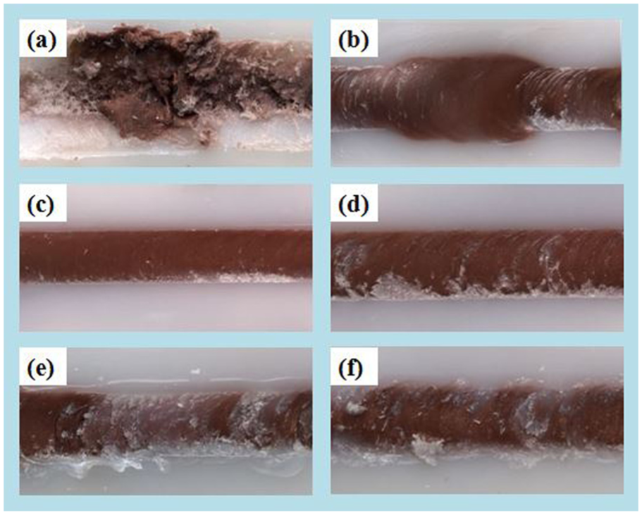
Surface appearance of samples fabricated with different FSP parameters: (a) in air, (b) S1, (c) S2, (d) S3, (e) S4 and (f) S5.
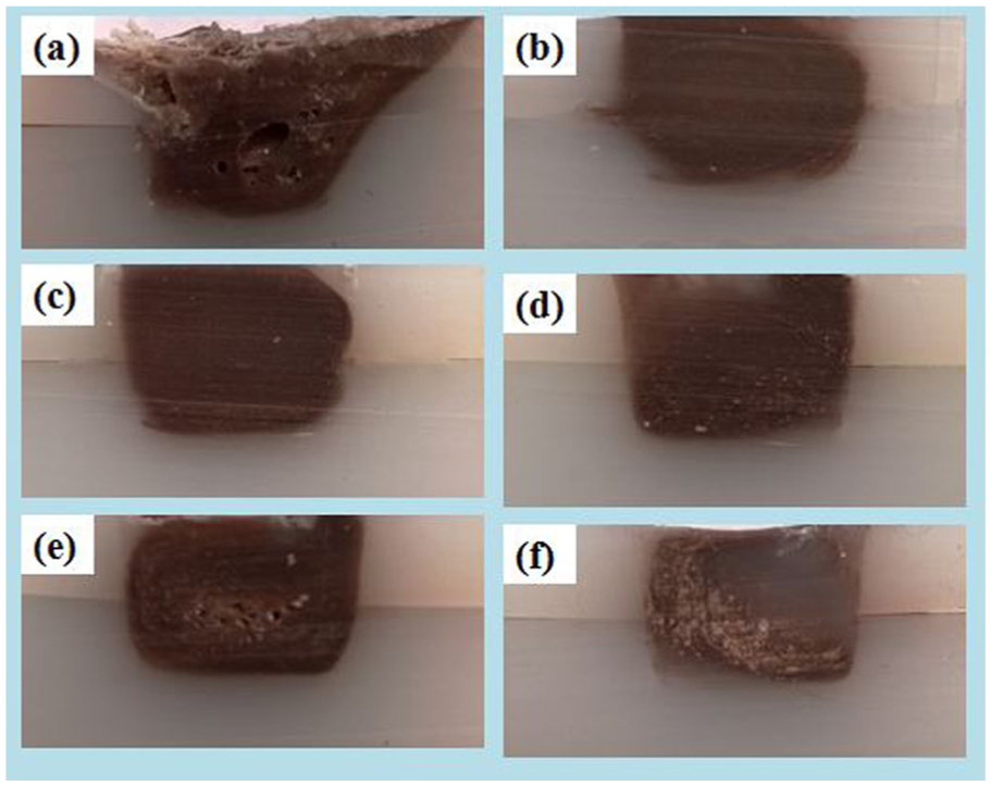
Macrostructure of samples fabricated with different FSP parameters: (a) in air, (b) S1, (c) S2, (d) S3, (e) S4 and (f) S5.
As can be seen from Figure 4(b) and (f), the surface of the submerged sample was smooth. There are no apparent defects on the cross section of the submerged sample (Figure 5(c)). However, the surface of the conventional FSP sample was very rough. The materials were squeezed out from the processed region. Furthermore, the conventional FSP sample shows the presence of voids in the processing regions. Polymeric materials had a low thermal conductivity, which would lead to a high-temperature gradient. The heat mainly concentrated in the processing regions and the material flow in this process was difficult to control. The rotating shoulder threw away the soft material from the processed region. Thus, during conventional FSP of the polymers, the problem was how to promote uniform cooling rate throughout the processing zone. SFSP not only reduced the peak temperature but also effectively controlled the thermal cycle.22,23 The surface of the submerged sample appeared smooth because of the lower temperature and more cooling rate under the submerged condition.
According to Figure 4, the processing surface displayed different morphologies; the crown formation at the processing zone depended on the traverse speed applied. With the increase in the traverse speed applied, the surface quality became poorer due to the high cooling rate of polymer crystals. 8
The macrographs of the processed zone at different transverse speeds are presented in Figure 5. From the macrostructure analysis, the variation in the processed zone was related to transverse speed. The processing zones using FSP were prone to defects such as crack, voids and air bubbles because of insufficient or excess heat input. 24 Saeedy et al. 25 found that the heat input was proportional to the inverse of traverse speed. Increasing the transverse speed would decrease the maximum temperature and the amount of molten material inside the processed zone but increase the heating and cooling rates. 26 It led to the formation of a large number of voids (Figure 5(e)). When the transverse speed was too high (90 mm/min), there would be high heterogeneity in the processed zone (Figure 5(f)). It appeared that lower transverse speeds more easily promote the formation of the composites. Under lower traverse speed, the HDPE–Cu mixing time was increased. The more mixing time caused the more homogeneous distribution of Cu powders among HDPE matrix. Although lower traverse speed could promote the material flow, a large amount of friction heating concentrated in the processed zone due to the low thermal conduction of polymeric materials, and the air bubble appeared along with the material melting. Figure 6 shows the air bubble at the interface of the sample produced at the traverse speed of 15 mm/min.
The air bubble at interface of S1 sample.
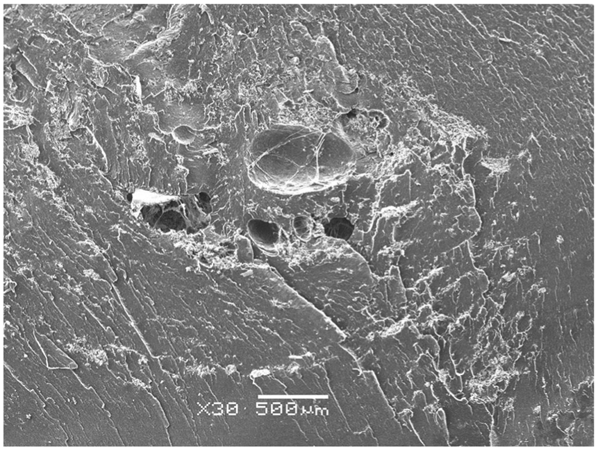
The SEM microstructures taken from the fracture surfaces of HDPE–Cu composite samples made by SFSP at different parameters are shown in Figure 7. It can be concluded that the transverse speed has high influence on the distribution of Cu powders. At a lower transverse speed, the Cu particles were refined and more uniformly distributed. When increasing the transverse speed, the agglomeration of the particles was observed, particularly the S5. The agglomerated particles were identified as Cu (Figure 8) via energy-dispersive spectroscopy (EDS). As a complex process, FSP included non-uniform material flow. 24 The character of the processed zone was affected by the tool parameter and process parameter which dictated the overall heat input. In FSP, the “processing time,” the time during which the material has undergone the thermal–mechanical influence, was influenced by transverse speed. 26 It is true that the processing time is longer at low transverse speeds, which promote the mixing of Cu powders and matrix. 7 Meanwhile, the matrix flow stress was reduced at a lower transverse speed, and the particle flow in the matrix became easy. Consequently, it led to an enhanced state of dispersion of Cu powders in HDPE matrix at a low transverse speed. With the increase in the transverse speed, the material flow became inadequate and the Cu and HDPE were not sufficiently mixed, which resulted in the formation of agglomeration.
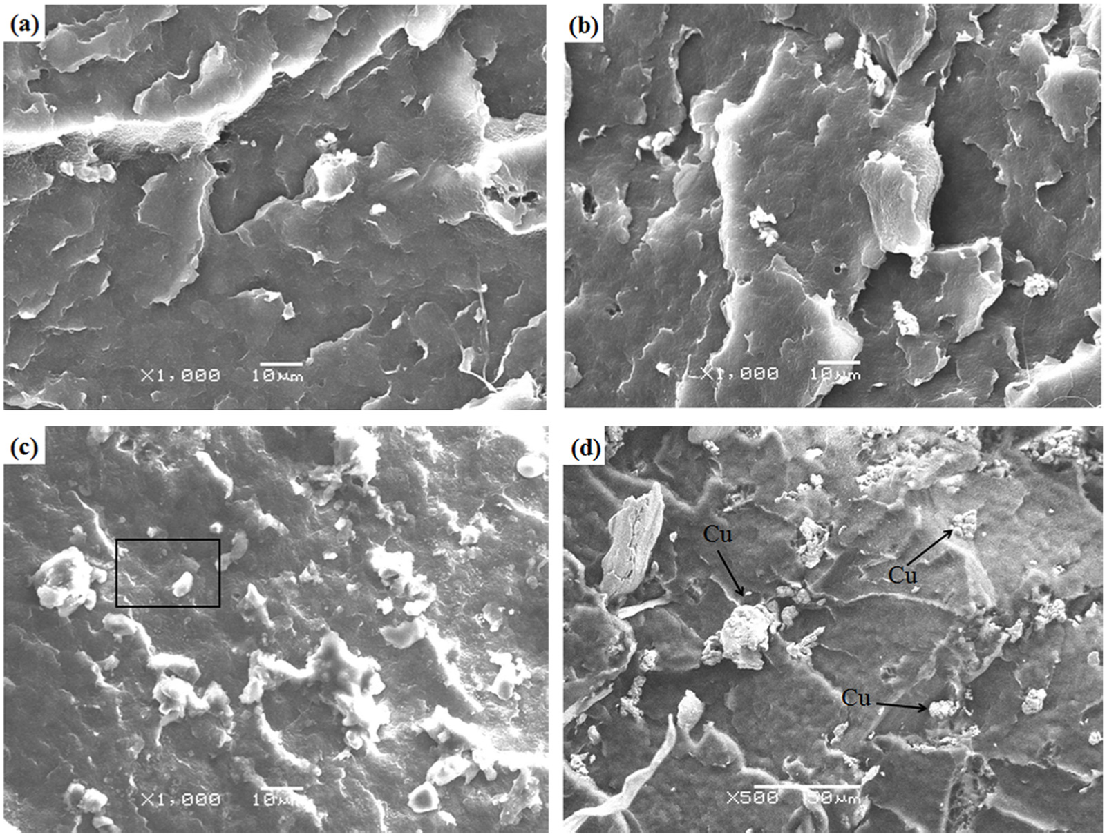
SEM images of the samples by SFSP at different parameters: (a) S2, (b) S3, (c) S4 and (d) S5.
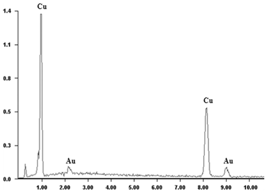
The EDS analysis of SFSP specimen (S5).
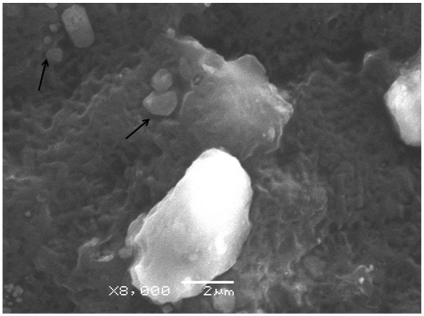
The SEM of Cu around the HDPE matrix from Figure 8(c) is shown in Figure 9. As can be seen, Cu and the HDPE matrix were slightly detached after fracture. It indicates that the bond between Cu and HDPE is weak. When the composite was stressed, the stress might transfer to the matrix and reduce the strength.
SEM micrographs taken from the fracture surfaces of HDPE–Cu composites.
Mechanical properties of composites
The tensile strength curves of the HDPE–Cu composites with varying transverse speeds are shown in Figure 10, and the maximum tensile strength of the composites was 20.7 MPa, which was lower than the tensile strength of the base metal (BM) of 22.5 MPa. The raw HDPE had high value of tensile strength, which depended on the chemical structure of HDPE. When the force was applied, the chains had enough time and space to orientate. However, adding powders to the HDPE matrix would reduce chain mobility, which caused a decrease in tensile strength. The reduction in the composite materials in tensile strength can also be explained by the model 26

where σC and σP are the tensile stress of the composite and matrix, respectively; the weighting factor K3 is the adhesion quality between the matrix and filler; and Φ denotes the volume fraction of the filler. Generally, the lower K3 value refers to the better adhesion quality. Polyethylene was generally considered as a non-polar material, and it had poor adhesive properties and low surface free energy. 19 In the HDPE–Cu composites, the adhesive property of the matrix and filler was weak (Figure 9). In this case, a decrease in tensile strength was observed. And the fillers represented defects and stress concentrators, which reduced the tensile strength of the matrix. This was consistent with the above SEM analysis in Figure 9.
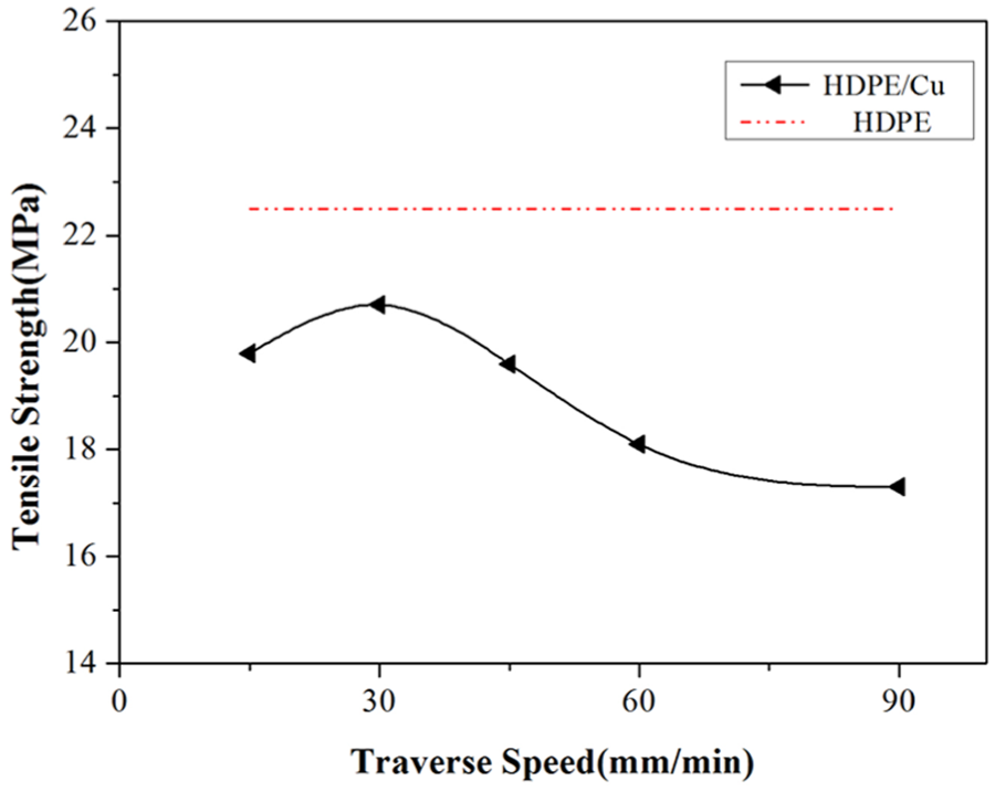
Tensile strength of BM and SFSPed samples at different traverse speeds.
From Figure 10, it can also be seen that the tensile strength increased at first and then decreased with an increase in traverse speed, and the maximum value was obtained at 30 mm/min. The traverse speed in the tensile strength of HDPE–Cu composites has two functions. On one hand, during the FSP, the lower traverse speed would extend the time in the stirring zone so that Cu powders and HDPE matrix will have plenty of time to mix. Therefore, it induced better dispersion of Cu powder in HDPE matrix, and good dispersion of Cu in the HDPE matrix finally increased the tensile strength values. However, decreasing the traverse speed causes too much heating concentrated in the processing regions due to the traverse speed influencing the heat input per unit length of the processed zone, 27 which induced many air bubbles (Figure 6). On the other hand, the stirring zone was compressed at high traverse speed, leading to higher thermomechanical stress on the composites which enhanced the dispersion of Cu powders in the matrix. 8 But it also caused lower heat input, which in turn reduced the stirring of the materials because of poor flow ability in the processed zone, resulting in the formation of voids. The defects such as air bubbles and voids acted as stress concentration points in the composites leading to a decrease in tensile strength values of the composites. According to the test results, it is found that a better sample could be obtained at lower traverse speed.
The dependence of microhardness of the composites on the traverse speed of Cu filler is shown in Figure 11. According to the results, the microhardness of the composites had much more higher values than those of HDPE matrix. It also can be seen that the microhardness of the composites decreased with an increase in traverse speed. There are two main reasons in increasing composites’ microhardness. First, the composites were less crystalline and therefore stiffer than HDPE matrix, which would be mentioned in the later analysis; second, the size and distribution of Cu particles played a significant role because the fillers were much stiffer than the HDPE matrix. Thus, the microhardness of the composites has higher value at lower traverse speed because better distribution of Cu particles was prone to be obtained in this case.
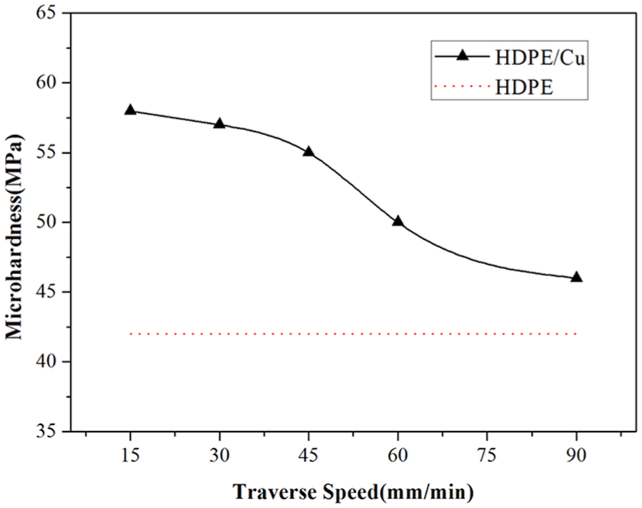
Microhardness of BM and SFSPed samples at different traverse speeds.
Thermal properties of composites
DSC was used to evaluate the effect of the Cu on the crystallinity of the HDPE–Cu composites. The HDPE sample which was processed under the same parameters was also scanned for comparison with the composite samples. Figure 12 shows heat flow measurements of the representative samples used in this study during heating from 25 °C to 200 °C. The melting behavior of HDPE composites was indicated in the thermograms as endothermic peaks. As can be seen from Figure 12, the HDPE shows an endothermic peak at 141.2 °C, while the HDPE–Cu composite shows an endothermic peak at 138.2 °C. There is no significant change when Cu powders were added to HDPE, which indicates that the melting point of HDPE–Cu composites had no apparent variation.
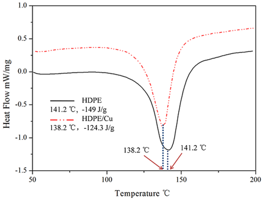
Heating thermogram for DSC of the HDPE and composite (S2) samples.
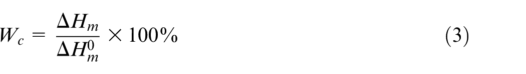
The crystallinity of the materials can be quantified by 28
where
Conclusion
In this article, HDPE–Cu composites were successfully fabricated by SFSP. It has been found that the addition of Cu particles had significant impact on the mechanical properties of HDPE. The following conclusions could be drawn from the experimental results:
Cu particles reduced the tensile strength and increased the microhardness of HDPE.
The morphology of the composites was affected by the traverse speed.
The addition of Cu particles decreased the crystalline content of the composites.
SFSP has great potentiality for fabricating polymeric surface and bulk materials.
Footnotes
Declaration of conflicting interests
The author(s) declared no potential conflicts of interest with respect to the research, authorship and/or publication of this article.
Funding
The author(s) disclosed receipt of the following financial support for the research, authorship, and/or publication of this article: This study was supported by the National Natural Science Foundation of China (Grant No. 51475232). This is a project funded by the Priority Academic Program Development of Jiangsu Higher Education Institutions.