
Abstract
The material removal phenomenon of sparking and melting in micro-electro-discharge-milling process occurs at inter-electrode gap of dimension less than 50 µm. The behavior of fluid flow properties at inter-electrode gap is not well discussed in the literature and its information will be useful to understand the material flow behavior and tool wear in micro-electro-discharge-milling process. Based on our previous findings, it was well recognized that tool rotation is an inherent part of micro-electro-discharge-milling and directly influences debris flushing and redeposition. Also for a stable machining performance, flow of dielectric will play an important role in flushing away debris from the gap. The objective of this work is to investigate the fluid flow along the inter-electrode gap and to study its effect on debris movement and molten metal redeposition. The fluid flow along the narrow gap of micro-electro-discharge-milling process for different machining conditions is analyzed by computational fluid dynamics simulation. By particle simulation, the effect of different sized particles formed at various positions and their subsequent movement was also analyzed. The computational fluid dynamics analysis results were validated with scanning electron micrographs obtained for various machining conditions of the experiments. The effect of inlet nozzle velocity, tool rotation and size of electrode gap on the dielectric fluid flow was primarily reported and the findings were later superimposed on particle injection velocity to determine the movement of debris along inter-electrode gap. The effect of debris movement on redeposition at workpiece/tool surface and its ejection from inter-electrode gap is recounted.
Keywords
Introduction
Miniaturization is the basic strategy for today’s manufacturing environment throughout the world. Mechanical and electronic products are in great demand having small size and lighter weight. This necessitates the use of precision machining with advanced technology. Among various advanced machining techniques such as laser, three-dimensional (3D) printing and ion beam, micro-electrical discharge machining (µEDM) finds its importance because of its unique advantage of low cost and clean environment. However, the phenomenon occurring at inter-electrode gap (IEG) in µEDM process is very complex and attracts many researchers all over the world. Discharge phenomena in µEDM occur over a very short time period in a narrow gap filled with dielectric, bubbles and debris, thus making both observation and theoretical analysis extremely challenging. 1
Micro-electro-discharge (µED) milling is similar to µEDM except that a rotating cylindrical tool electrode is directed along a programmed trajectory to achieve the desired shape. The main advantage of µED-milling is that it avoids manufacturing of complex tools required for achieving 3D profiles. High machining aspect ratio, capability to machine any hard conductive material and low machining cost are the advantages of µED-milling. Currently, µED-milling is mostly used for the production of micro-cavities with high aspect ratio and tools such as micro-molds for micro-injection molding. 2
In order to understand the physical phenomenon of µED-milling process, it is necessary to explain the crater formation, material removal in the form of debris and dielectric motion at IEG. Accumulation of debris in discharge gaps usually causes a poor discharge, which not only reduces material removal rate (MRR) but also severely damages the machined surface. 3 In µED-milling process, material removal occurs intermittently during or just after the discharge duration while the generated bubble is expanding. 4 The plasma expands within a few microseconds after dielectric breakdown and its diameter is much larger than the discharge crater. Whereas the heat source diameter is smaller than the plasma diameter but larger than the crater diameter.5,6 The effect of pressure drop such as cavitation of the molten metal and degassing of solution gas in the molten metal is one of the possible causes of the material removal. 7 The evacuated molten metal from the crater either flows certain distance along with dielectric or cools instantaneously to form debris particles of varying sizes. Due to resolidification of the molten material, recast layer or white layer is formed on the machined surface. The thickness of the recast layer depends on different parameters such as peak current, pulse on time and dielectric flushing. 8 Dielectric plays an important role in EDM process. Different dielectrics such as oil based and water based are used in EDM process. The chemical composition of the dielectric has great effect on the overall EDM performance. Distilled water or deionized water has better processing performance than kerosene and urea solution.9,10 Dielectric mixed with nano powders improves surface finish, topography and MRR in µEDM. 11 Dielectric flushes the debris from the gap which is useful for uniform discharge. The dielectric flushed in the gap does not affect plasma tunnel and crater developed in the gap. 12
It is well agreed in the literature that the physics of µEDM process is complex and many contributions have been reported on the analyses of plasma formation, crater mechanism, heat transfer and so on. But very few researchers have used computational fluid dynamics (CFD) approach to simulate and study the machining aspect of a process. Mihić et al. 13 used CFD simulation to study the fluid flow in grinding process; obtained distribution of temperature, pressure, velocity and liquid volume fraction; and determined the flow patterns, including useful and wasted flows. Okada et al. 14 investigated the fluid flow from the machined kerf of wire EDM. The flow field, debris motion and better jet flushing conditions of working fluid from the nozzles were analyzed by CFD simulation. Haas et al. 15 designed and analyzed dielectric injection nozzles of wire EDM process by CFD simulation for improving the cleaning process in the gap. When the spark frequency and power are high, the machining speed is governed mainly by hydrodynamics. Pontelandolfo et al. 16 investigated the dynamics of the dielectric fluid in the die sinking EDM process. A CFD analysis was used to know the size, shape and kinematic properties of the electrode. Different combinations of axis jerk, acceleration, speed and movement of the electrode were studied using different dielectric fluids.
Researchers have also studied the use of different dielectrics in µEDM and their effect on performance. But very few studies have been reported in the literature on the fluid flow pattern and debris movement over a narrow IEG of µED-milling. The pattern of fluid flow and fluid velocity determines the size and shape of debris particles, its movement and subsequent redeposition of molten metal in the gap. So it becomes necessary to study the fluid behavior at IEG for µED-milling process.
The objective of the article is to study the dielectric flow pattern of µED-milling process along the gap between the tool and workpiece. CFD tool is used to analyze the fluid flow patterns, velocity profiles and debris movement in the discharge gap. The results are compared with the experimental machined images obtained using scanning electron microscope (SEM) to validate. The effect of gap size, inlet velocity and tool diameter on dielectric flow velocity along IEG is studied. Rotation of the electrode causes a stirring action in molten metal flow with the corresponding flushing and non-uniform deposition. Contour plots are obtained to show the flow pattern. Eddies are formed near the tool which acts as a secondary stirrer in the process. A non-uniform redeposition is observed on the surface as observed in real process.
Modeling and problem formulation
Model description
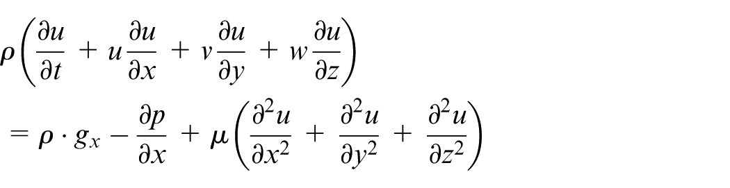
In µED-milling process, the tool rotates and moves along a programmed trajectory. When potential difference is applied on the electrodes, a constant gap is maintained between the tool and the workpiece, and spark happens along the side and bottom surfaces. The rotation of the tool ensures sparking is uniform and continuous, and its shape is replicated on the workpiece along the trajectory. Since sparking behavior along the tool surface is same throughout its length, only a cross section is considered for CFD analysis. The top view of two-dimensional (2D) model used for CFD analysis of the dielectric fluid flow is shown in Figure 1. The tool electrode of diameter 500 µm is rotating in the clockwise direction and fed from right to left direction. The constant IEG of 50 µm is maintained between the tool and the workpiece. The width and length of the micro-channel are 600 and 1300 µm, respectively. The electrodes are submerged in the dielectric and additional dielectric for circulation enters through nozzle. For ease of simulation, the inlet and outlet of fluid flow are considered on either side of the wall as shown in Figure 1. The imaginary wall (does not exist in actual process) of length 200 µm is located at the center to distinguish between the inlet and outlet. The presence of wall will not affect the flow pattern near the tool electrode. Rotating tool electrode, which is a solid domain, was meshed with quadrilateral elements and the fluid domain was meshed with triangular elements as shown in Figure 2. As the dimensions are in micron meters, the entire domain was fine meshed to improve the accuracy of the results. The CFD simulations are performed with commercial ANSYS FLUENT software. The governing differential equations are Navier–Stokes equations of the flow physics solved numerically on a computational mesh. Navier–Stokes momentum equation is as follows
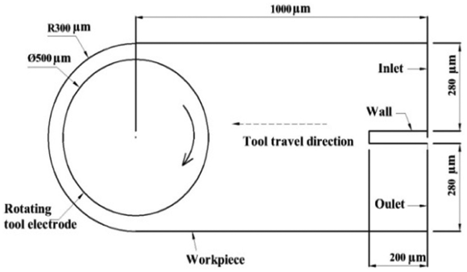
Schematic diagram of 2D model of micro-channel used in CFD analysis.
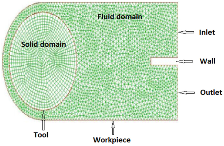
Discrete meshing of solid and fluid domain of 2D model.
where
List of CFD parameters used for the analysis. 13
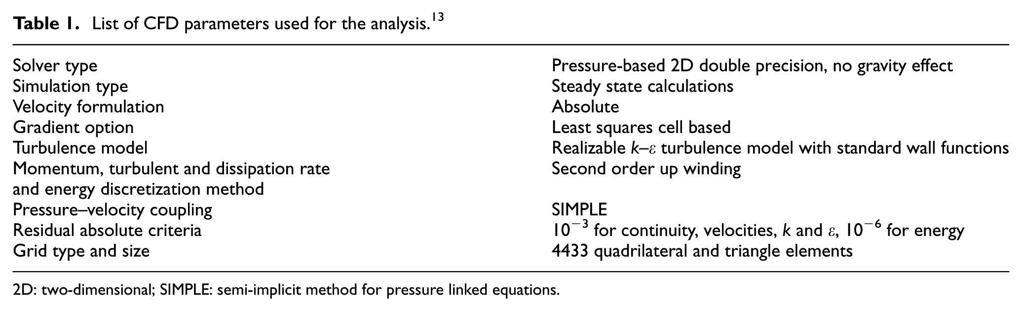
2D: two-dimensional; SIMPLE: semi-implicit method for pressure linked equations.
The IEG is divided into equal number of points and the selected points considered for analysis are shown in Figure 3. The points are represented as I, II and III which indicate positions near the workpiece, center of IEG and near the tool, respectively. The results of dielectric flow velocity at IEG are discussed with respect to these points. At each position, three values are taken and the average value at that point is reported.
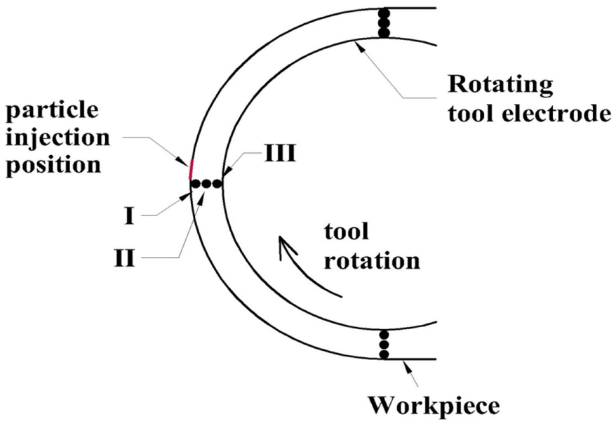
Schematic diagram representing the analysis points and particle injection zone for model study.
Dielectric fluid
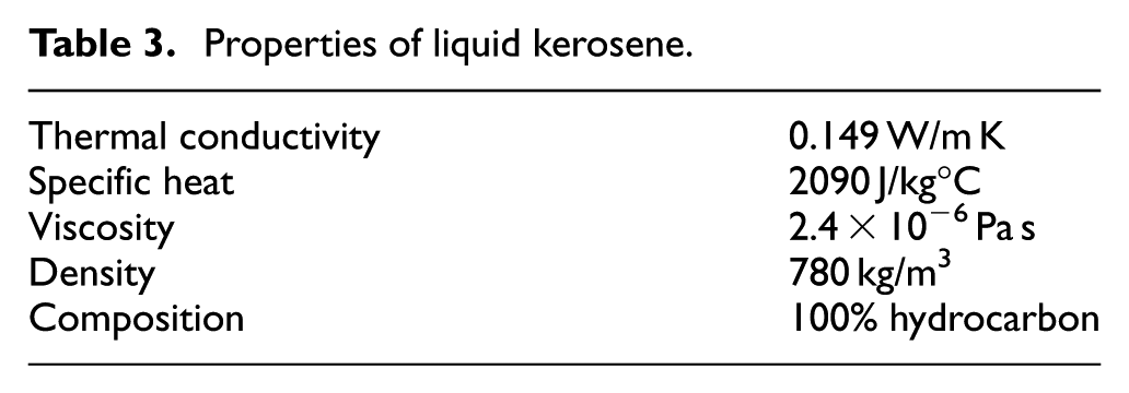
The dielectric fluid serves various functions such as insulation, ionization, cooling of electrodes and removal of debris particles. Several dielectric fluids are used for EDM applications. Each dielectric has unique advantage over the other. The machining characteristics of various dielectric fluids are given in Table 2. In µED-milling, the dielectric fluid with lower viscosity improves the machining efficiency. Liquid kerosene is a hydrocarbon which has very low viscosity and it flushes very well. Due to this advantage of kerosene, it is used as dielectric in µEDM application. The dielectric fluid used for CFD simulation is liquid kerosene, the properties of which are given in Table 3.
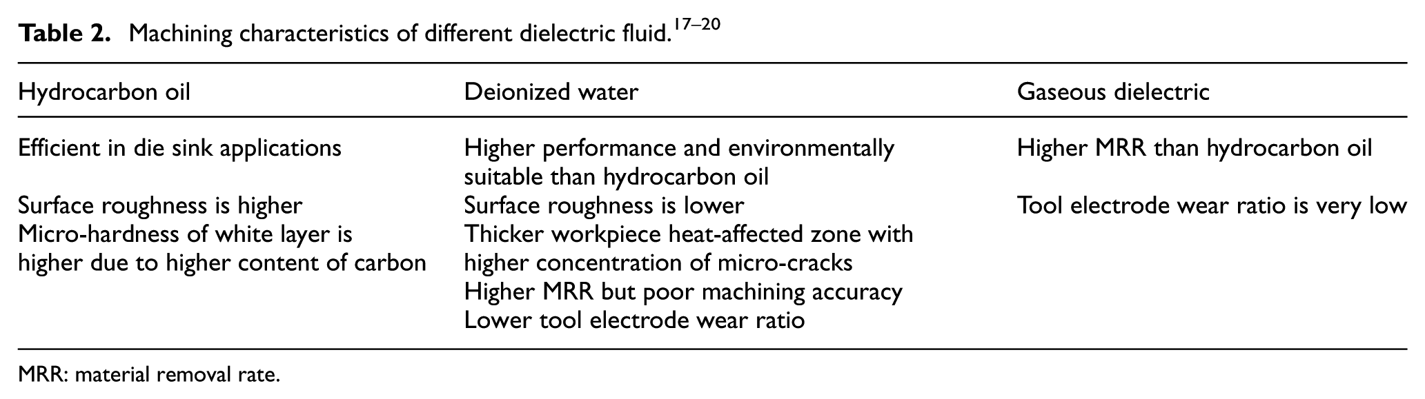
MRR: material removal rate.
Properties of liquid kerosene.
Results and discussion
Effect of IEG
A constant gap of 50 µm or less will be formed between the tool and the workpiece during machining in µED-milling process. The sparking occurs continuously along the tool and workpiece surface and flow of dielectric ensures removal of molten metal and debris from the gap. The continuous motion of dielectric is created by tool rotation due to the effect of centrifugal force and agitation. The dielectric fluid not only helps in flushing the debris but also drives fresh fluid into the gap. Molten metal ejected from the electrode can either flow as a secondary fluid or form globules which on subsequent cooling generates spherical particles or debris.21–23 The size and shape of the globules depend on the discharge energy, crater size and amount of molten metal expelled. When the quantity of the expelled molten metal is larger, then it deposits on the nearby surface forming redeposited layer. Whereas when the quantity of the metal is less, then stirring action caused by tool rotation breaks globules into small particles. Since many phenomena happen at the gap, its size is considered as a parameter to determine the dielectric fluid behavior.
The CFD simulation is conducted on liquid kerosene as dielectric with inlet nozzle velocity of 0.01 cm/s. The effect of the gap on the average dielectric velocity is studied for three different tool rotation speeds, namely, 100, 500 and 800 r/min. The gap is varied in two ways by varying the tool diameter and keeping the width of the machined micro-channel constant and vice versa. The sizes of gap considered for simulation are 30, 40 and 50 µm. Figure 4 shows the effect of IEG on dielectric velocity when micro-channel width is kept constant and electrode diameter is varied to change the gap. CFD simulation result shows that as the gap size increases, the average velocity of dielectric in the gap decreases for positions II and III and this drop is maximum when the velocity is measured near the tool. At position I, the average velocity of dielectric remains constant for all conditions. As tool r/min increases, the average velocity across the gap increases as expected. This implies that when the gap is small, the flushing is better if the debris appears close to the tool because of higher dielectric velocity at that position. But for a given position of IEG, the velocity does not seem to be affected by the variation in the gap. Thus, the fluctuation in voltage or irregularity in surface peaks which causes small variation in gap does not affect the dielectric movement along the IEG. In µED-milling process where the energy is less and the gap is small, this observation of increase in dielectric velocity will ensure continuous discharge and subsequent material removal which is needed for the process. The aid of tool rotation and the increase in dielectric velocity at small gap will provide effective flushing for µED-milling process. Figure 5 shows the effect of IEG on dielectric velocity when electrode diameter is kept constant and micro-channel width is varied to change the gap. The average velocity of the dielectric remains constant for various electrode speeds, which implies that an increase in the diameter of the electrode will increase the centrifugal force on the fluid increasing its velocity in the gap.
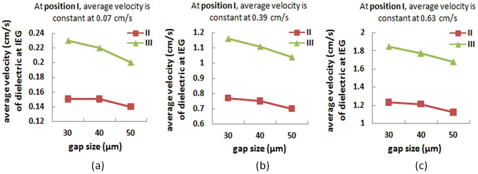
Effect of gap size on average velocity of dielectric at IEG for electrode speed of (a) 100 r/min, (b) 500 r/min and (c) 800 r/min. Micro-channel width is kept constant and electrode diameter is varied to change the gap.
Effect of gap size on average velocity of dielectric at IEG for electrode speed of 100 r/min. Electrode diameter is kept constant and micro-channel width is varied to change the gap.
Effect of inlet velocity of dielectric fluid
The inlet velocity refers to the jet velocity of the dielectric near the entrance of the micro-channel. This flow is to ensure recirculation of the dielectric in the micro-channel. Since the fluid is flowing inside and outside of the channel in the same position, the micro-channel entry cross section is divided into the inlet and outlet with a partition wall in-between as explained earlier. The value of the velocity at the inlet is varied from 0.001 to 100 cm/s for the initial study. It is observed that for the value of inlet velocity between 0.001 and 0.1 cm/s, the average dielectric velocity at IEG is constant. But when the value increases between 10 and 100 cm/s, there is a significant rise in the velocity of the dielectric as shown in Figure 6. This increase in dielectric velocity at IEG is due to the nozzling effect near the gap inlet. The effect is further enhanced by an increase in tool rotation speed as seen in Figure 6 which clearly shows that the two effects are independent of each other. This behavior of an increase in dielectric velocity at IEG happens for all the positions, and hence irrelevant of where the debris appears in the gap, flushing will be efficient.
Effect of inlet nozzle velocity on average velocity of dielectric at IEG for electrode speed of (a) 100 r/min, (b) 500 r/min and (c) 800 r/min.
But on studying Figure 7, it was observed that lower value of inlet velocity such as 0.001, 0.01 and 0.1 cm/s creates eddies in the back of the tool which acts as secondary stirrer. Any debris appearing near the zone will not be allowed to enter the gap again. Whereas when the velocity is as high as 100 cm/s, the eddies with smaller size are observed. Also, the effect of electrode speed is not observed due to high dielectric inlet velocity. Figure 8(a) shows the value of static pressure at gap inlet and exit for dielectric inlet velocity of 0.01 cm/s. It is observed that the pressure is larger near the gap inlet and smaller at the gap exit. At low inlet velocity, eddies reduce the dielectric flow in the IEG, and hence dielectric fluid drag happens only by the tool rotation. Also, fluid flow patterns generated may create region which are starved of dielectric. This can be the reason for redeposition near the gap inlet as observed in SE micrograph of channel as shown in Figure 8(b).
Contour plot showing velocity pathlines (cm/s) of dielectric at various electrode speeds and nozzle inlet velocities.
(a) Static pressure pathlines (Pa) at 500 r/min and 50 µm gap and (b) SE micrograph showing tool rotation effect on molten metal flow and subsequent higher deposition of metal at the bottom.
Effect of change in dimension of micro-channel and tool electrode diameter
The dimension of the micro-channel and electrode is changed without changing the gap width. The size of the micro-channel considered is 600, 500 and 400 µm with the corresponding tool diameter of 500, 400 and 300 µm, respectively. This can definitely happen in real time while machining different dimension channels with same energy conditions. For this study, the gap width of 50 µm was kept constant for all combinations. The average velocity for different size combinations is shown in Figure 9. As expected, when tool rotation speed increases, the corresponding dielectric velocity at IEG increases, and when the diameter of the tool decreases the average velocity of the dielectric decreases. So the higher the tool diameter with constant gap, the greater the centrifugal force, the greater the velocity and better is the flushing as explained earlier.
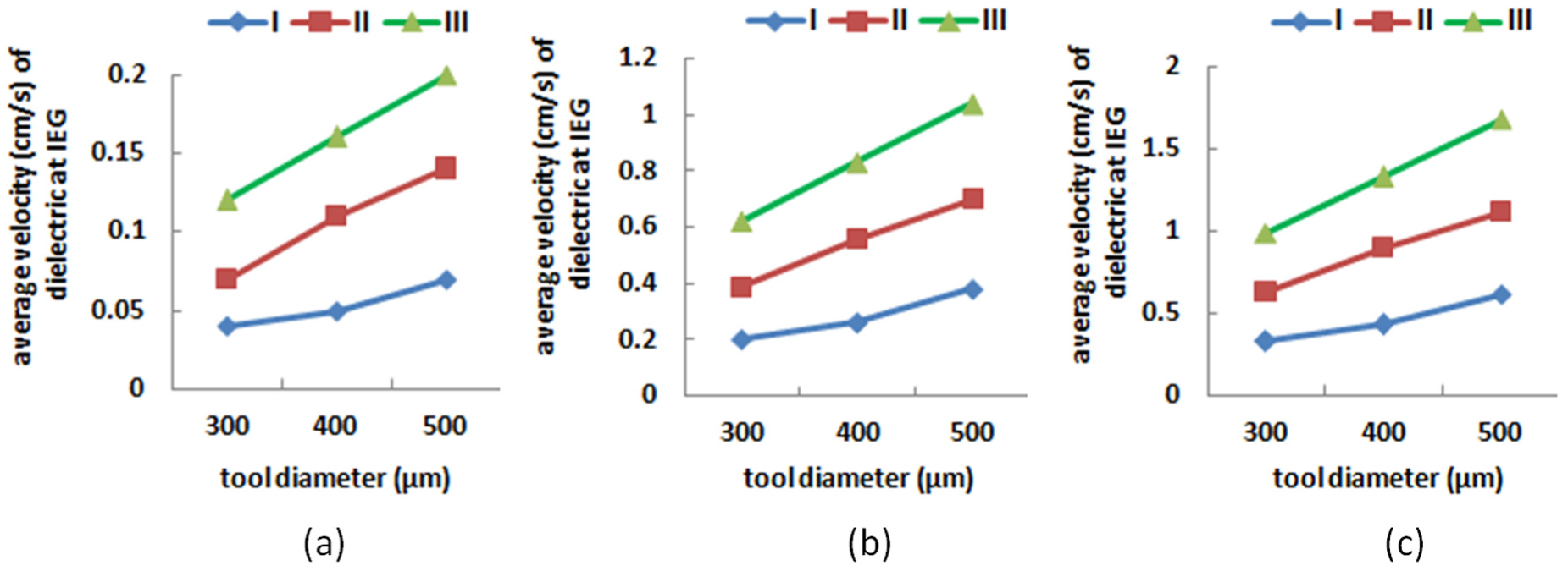
Effect of tool diameter on average velocity of fluid at IEG for electrode speed of (a) 100 r/min, (b) 500 r/min and (c) 800 r/min.
Debris particle
Debris particle trajectories
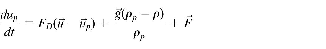
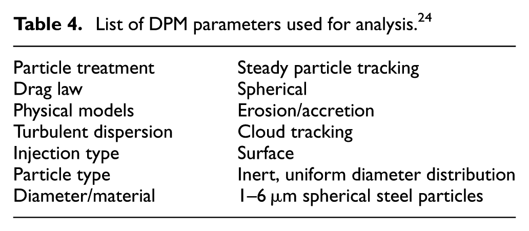
Discrete phase modeling (DPM) is used to study the movement of debris particles at IEG. The Lagrangian discrete phase model in ANSYS FLUENT follows the Euler–Lagrange approach. The DPM parameters used for particle simulation are listed in Table 4. The fluid phase (primary phase) is treated as a continuum by solving the Navier–Stokes equations, while the dispersed phase (secondary phase) is solved by tracking a large number of particles through the calculated flow field. The dispersed phase can exchange momentum, mass and energy with the fluid phase. The volume fraction of the dispersed phase is less than 10%–12% of the fluid phase. The trajectory of a discrete phase particle is calculated by integrating the force balance on the particle which is in Lagrangian reference frame. The force balance equation per unit mass of the particle is given as
List of DPM parameters used for analysis. 24
The left side of the equation (dup/dt) is the net particle inertia and the right side is the drag force, gravity force and additional forces in order. 24
In this study, different spherical size particles are injected from the work surface and the movements of the particles are studied. The injection points can be referred as the position of craters in actual process. It is possible to have infinite number of craters along workpiece surface and all these points could be the source of molten metal and debris. For simulation, one such point is considered as shown in Figure 3 where the effects are significant. The injected particles will travel along the gap and possibly attach themselves either on workpiece surface or on tool surface. In actual process, the attachment is possible only when the molten metal reaches the tool or workpiece surface with sufficiently larger temperature. But, due to the continuous circulation of the dielectric, the molten metal will have larger tendency to cool and hence becomes debris before getting them attached to either surface. Therefore, the two critical parameters that will decide the formation of redeposition or molten metal attachment are the distance traveled by molten metal and the time it takes to reach the surface. Figure 10 discusses the behavior of the particles to reach the workpiece for various injection velocities.
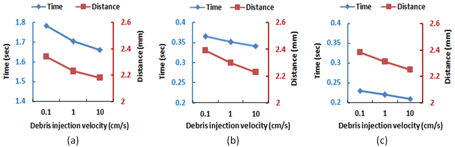
Effect of debris injection velocity on time and distance traveled by debris particle to reach workpiece surface at electrode speed of (a) 100 r/min, (b) 500 r/min and (c) 800 r/min.
As discussed earlier, redeposition occurs on a surface near the gap inlet. For simulation study, the surface near the gap inlet was applied with “trap” boundary condition considering clockwise rotation of the electrode. The distance traveled and the time required by the debris particle from the injection position to reach the trap surface were calculated. It is observed from Figure 10 that as the debris injection velocity increases, the time and distance traveled by the debris decrease. Due to this high injection velocity, debris will move near the tool electrode, rotating with less circumferential distance and less time. It is clear from Figure 10 that the time required by the debris to reach work surface is less at higher r/min and it is constant for various values of debris injection velocity.
Deposition of debris particles
In DPM study, deposition of the particles is studied for different electrode speed and particle injection velocity. Due to tool rotation at high speed, eddies are created in the dielectric fluid flow. These eddies are formed at the back of the rotating tool as observed in Figure 7. Eddies contribute fluctuation to fluid velocity in addition to mean fluid velocity. When the particles are dispersed in the flow, their trajectories are subjected to change based on the effect of mean flow velocity and local fluctuation. The deposition of particle depends on whether the particle could travel past the eddy and go toward the work surface. This depends on the length of travel of the particle with respect to eddy length. The detailed discussion is presented by Jin. 25 When the particle travel length is larger than the eddy length, the particle can pass through it without decay and gets closer toward the entry of gap. Here, eddy creates stagnation point which is the region starved of the dielectric and possible place for the particles to accumulate and deposit. Since the particles are at high temperature, they will stick to the surface to form deposited layer.
In ANSYS FLUENT, deposition is given by accretion rate. Particle erosion and accretion rates are calculated at wall boundaries. The accretion rate is calculated in units of material addition/(area − time), that is, mass flux (g/mm2 s). The accretion rate is defined as
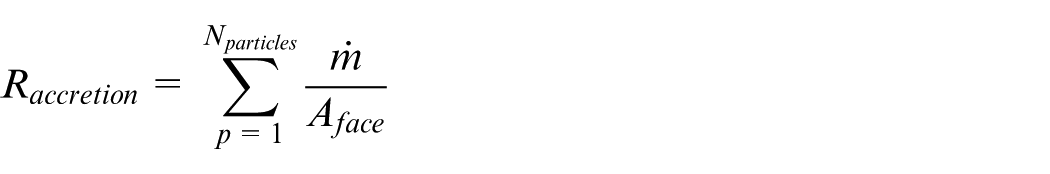
where Aface is the area of the cell face at the wall (mm2) and
It is observed that deposition of the particle is affected by tool r/min; when tool r/min is increased, the average deposition rate is also increased. This may be due to higher velocity of the dielectric fluid and better flushing of the debris particle from IEG. With the increasing particle injection velocity, it is observed that the deposition rate is decreasing, as shown in Figure 11(a). In this case, debris will move near the tool without touching the work surface and making multiple rotations. Figure 11(b) and (c) shows SE micrograph of debris on the work surface at various conditions. It is evident from the figure that debris particles are spherical in shape with various sizes that attach to work surface. Spherical debris particles of 1–2 µm are injected from the work surface for simulation study. It is seen from Figure 12(a) that with the increase in the number of particles, the average deposition rate increases as expected. But for the same number of particles, with the increase in diameter of the particles, the average deposition rate increases initially and then reduces with higher diameter of debris particles as seen in Figure 12(b). The deposition of the debris particle on the work surface depends mainly on the direction of tool rotation which is clearly seen in Figure 13(a) and (b). Figure 14 shows SE micrograph of the tool and work surface. It is clear from the figure that work surface is relatively rough than the tool surface due to redeposition of debris on the work surface. The amount of redeposition is less on the tool surface due to rotating tool which is inherent part of µED-milling process.
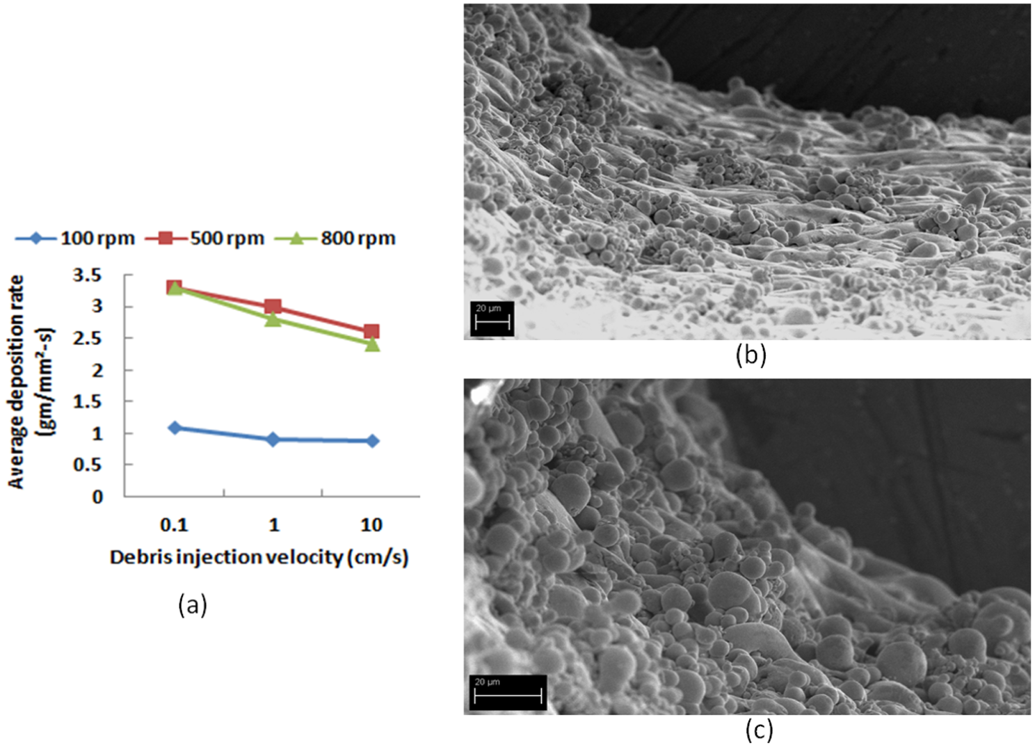
(a) Average deposition rate for various particle injection velocity. SE micrograph showing debris for electrode speed of (b) 100 r/min, 2000 µJ and (c) 800 r/min, 2000 µJ.
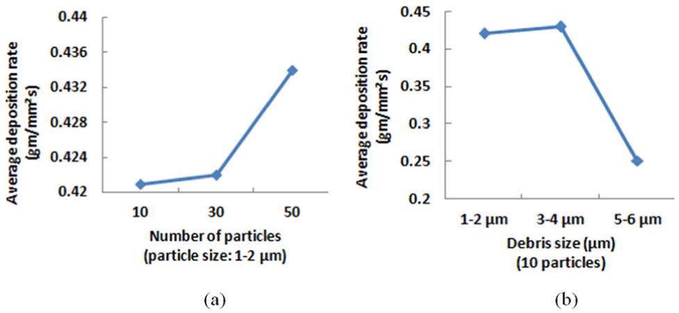
Average deposition rate for various (a) number of particles and (b) debris sizes.
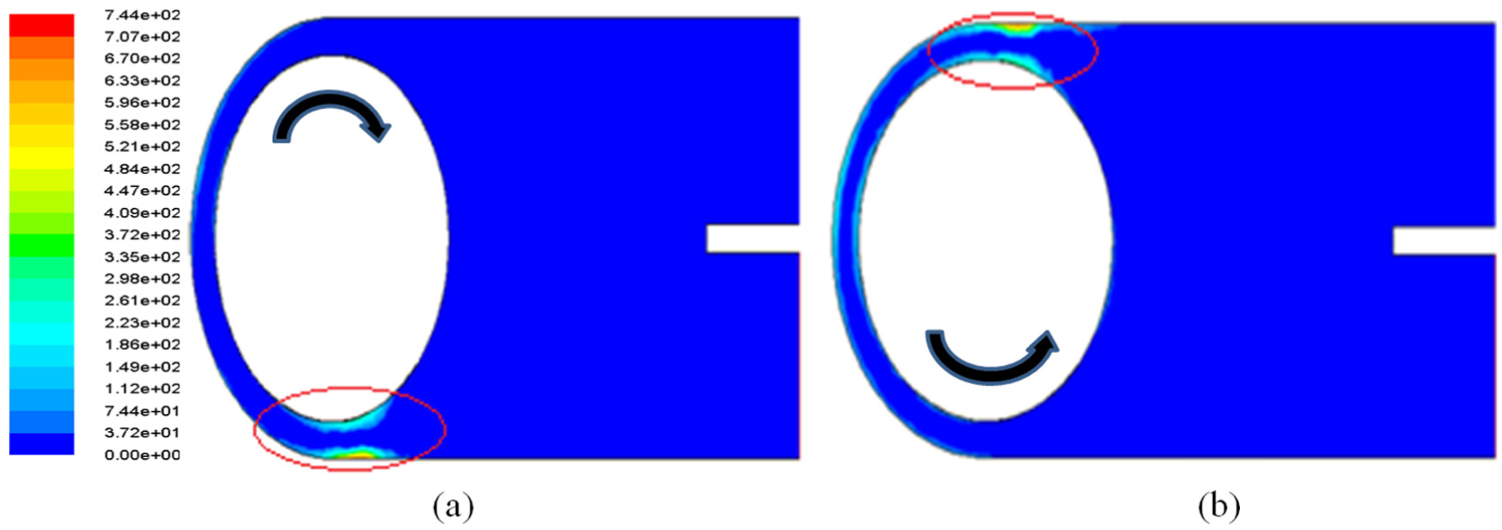
Average deposition rate (kg/m2 s) when (a) tool electrode rotation is clockwise and (b) tool electrode rotation is anticlockwise.
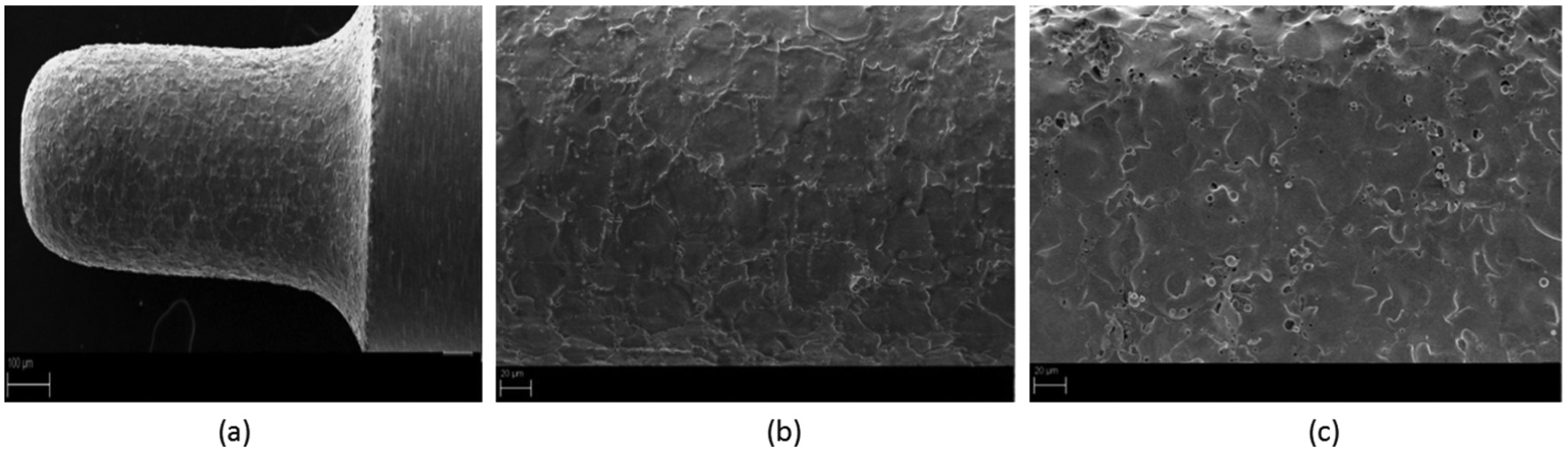
SE micrograph showing (a, b) tool surface and (c) work surface at 500 µJ and 500 r/min.
Conclusion
Removal of debris particles from the IEG plays an important role in µED-milling. Flushing of the debris particles from the gap is done by dielectric fluid. The size and shape of the debris and surface texture formed depend on fluid velocity in the gap. So it becomes necessary to study the dielectric fluid flow in a small electrode gap. In this study, the dielectric fluid flow pattern and debris movement in the electrode gap are investigated using CFD tool. The results of the simulation were compared with the SEM images of the machined surface. The effect of the change in electrode gap, inlet velocity of the fluid, the change in dimension of micro-channel and tool electrode diameter on fluid behavior in the gap was investigated. Also, the effect of tool rotation and particle injection velocity on debris movement at the IEG was investigated. The simulation results showed that as the gap size decreases, the average velocity of the fluid in the gap increases. In µED-milling as the electrode is rotating at high speed, the fluid in contact with the electrode will rotate at high speed and the speed reduces across the gap toward the stationary workpiece. The average velocity of the fluid in the gap is affected by the change in the inlet nozzle velocity, also there is a change in fluid pattern which creates eddies. Eddies act as a secondary stirrer in the process. They supply fresh dielectric in the gap and remove debris particles from the gap. The non-uniform redeposition is observed on the milled surface which is due to the rotation of the electrode, the variation of fluid velocity in the gap and formation of eddies. The deposition rate at IEG depends on electrode speed, particle injection velocity and size of debris particles.
Footnotes
Appendix 1
Declaration of Conflicting Interests
The author(s) declared no potential conflicts of interest with respect to the research, authorship, and/or publication of this article.
Funding
The author(s) received no financial support for the research, authorship, and/or publication of this article.