
Abstract
In this article, a new method for the rapid and economical production of ‘nutless’ bolted joins is presented, using a combination of two hole-making techniques, namely, form drilling and form tapping. The combined method achieves a quick way for the production of threaded holes on couples of dissimilar metal alloys, as it is the case of steels and aluminium alloys. After the simultaneous form drilling on the aluminium–steel pairs and followed by form tapping, a fastener can be introduced and screwed for achieving a tight bolted joint, without any necessity of nut. However, form drilling and threading are performed consecutively in the same machine tool, reducing the whole process time. The process parameters were studied for reducing the gap between surfaces and producing a good cup for making the posterior threading. Then, mechanical testing of several test pieces resulted in a similar behaviour than traditional bolted joints. Finally, corrosion tests were performed for a better understanding of the joint manufactured. In this way, savings in time and money are derived from the application of the approach. Target markets for the new approach are the light boilermaking industry in order to eliminate either welding beads or classical bolted joints using nuts.
Introduction
Currently, several industrial sectors ask for new approaches for joining metals of very different melting points, difference that makes welding process impossible, as it is the case of steel with aluminium. Here, welding is impossible with traditional thermal welding techniques because when steel is melting, aluminium alloys are already boiling. However, the joining of dissimilar materials is a necessity because in some cases, the structures need high-temperature resistance in one area and a good corrosion resistance in another, or toughness or wear resistance is required in one point, while high strength is required in another area. The joint of a stiff and high-strength metal such as steel with a light alloy is a good solution for applications in which the structural skeleton could be made out of steel, whereas skins and cover plates could be made in aluminium of the 5xxx group.
This technology, usually known as dissimilar material joining (DMJ), has been associated with metallic alloys including low and medium carbon steels and low-alloy steels, stainless steel, nickel, copper, and aluminium alloys and other non-metal materials. In the 1990s, there were research works involving titanium alloys, ceramics, polymers, and composites materials. Moreover, currently, in automotive applications, the joint of metals and plastics is really a research hot topic 1 leading to different friction or heat-based techniques applied to a number of duos of materials: (1) friction stir welding (FSW) in Al5083 and steel, 2 stainless steel, and copper 3 or friction stir spot welding; 4 (2) laser welding of Al5082 and steel 5 and different titanium alloys; 6 and (3) other techniques such as ultrasonic-assisted soldering of Cu-Al joints, 7 arc braze welding for Al-Fe dissimilar metal joints, 8 and microwave energy to weld dissimilar materials.9,10 In the case of joining of two metallic alloys, several factors must be taken into account including
Differences in melting temperatures.
Thermal expansion–contraction, mismatch during joining and in service.
Fixtures and constraint effects on joining stresses. 11
Formation of brittle intermetallic compounds during joining, which may lead to very frail joints.12,13
Heating–cooling rate effect on the microstructure of the joint, which could affect the strength and precision of the final joint.
Galvanic corrosion problems. 14
Particularly, hole making is a basic technology in automotive sector and aeronautics. For instance, vehicle builders use the flow drill screwing (FDS®; from the Swedish company EJOT©) in addition to metal inert gas (MIG) welding or punch riveting for high-strength sheet metal joints. In the case of aircraft turbines, the risk and cost are maximal in hole-making operations because of the large accumulated machining times. 15 Taking these requirements for DMJ into account, friction techniques are now being considered because they produce metal flow without melting, being the base of several techniques such as friction welding (FW; rotational and linear), FSW, friction drilling (FD), and form tapping (FT). Simulation techniques and computational approach were also used 16 to help to establish the effect of various flow-drilling screw processes and material parameters on the performance of the resulting flow-drilling screw joint, useful for analysing the whole-vehicle crash or even in simulations of vehicle component manufacturing.
The form process has several advantages with respect to traditional drilling. First, there is no need for cooling. In the traditional drilling process, coolant fluids are necessary to reduce friction and heat and to enhance chip evacuation, just the opposite of what FD intends. Second, unlike traditional chip removal processes, the main mechanism is friction, and no chip is expected. Therefore, it is often defined as a ‘clean’ or ‘green’ process. In the case of bolted joints, if the hole needs to be threaded, the need of a nut can also be avoided in some cases. This application is of great interest when it comes to make threaded holes in tubular or geometries that do not allow accessibility from the exit side such as appliances.
Most of the workpiece material in contact with the rotational tool becomes the generated cup (see Figure 1) with only a small burr at the part tool entrance side. There are two options when it comes to this upper burr; one possibility is that it is crushed between the tool ring and the piece, which implies that process is absolutely chipless. The other possibility is that the material is removed from the workpiece by a chip breaker located around the tool shank. Even in the latter case, the amount of material removed is small and is extracted out from the workpiece, and it still remains a clean process.
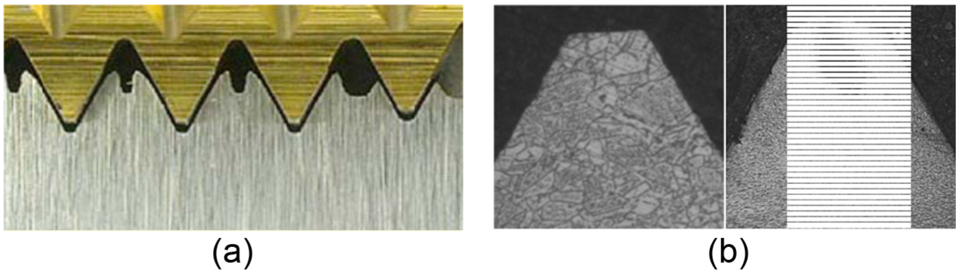
(a) Mechanism of thread formation with tap lobs and (b) microstructure of a thread produced with cut and roll taps.
Adherence of work material to the tool causes sliding conditions that tend to increase the frictional work done. The surface quality of holes is compromised by such conditions and may be a factor in reducing the fatigue life of joints. 17 Ku et al. 18 showed that the drilling bit conical shape (angle) and spindle rotational speed were the most significant machining parameters that affect hole inner roughness while friction contact area ratio was the only significant parameter for the bushing length. FD has been applied to different materials. The effect of tool bit parameter, tool geometry, and materials was also studied in Ozler and Dogru 19 for AISI 1010, showing that the hole zone temperature increased with increasing drilling speeds and decreasing feed rates. In the case of plastic materials, the effect of the cutting tool geometry was investigated in Abrão et al., 20 suggesting that the relation between the thrust force and delamination is not trivial. The possibility of making a pre-hole is offered in Demir and Özek, 21 according to the thermal conductivity of aluminium alloys and a nickel-based superalloy by FD in Lee et al., 22 where the results show that higher rotation speed and faster feed rate achieve better roundness and roughness.
Once the hole is open and the cup formed, the FD tool is extracted and FT process is performed. Threading process is widely spread in a lot of mechanical applications since it is essential in the procedure to produce screw joints, the most extended way of assembly of mechanical components. Two methods can be used to create an inner thread, either by forming or by cutting. So, in the case of forming, the thread is generated due to deformation of the raw material in a cold working way, whereas in the case of cut tapping, thread is obtained by chip removal as it is common in other machining processes. 23
This work proposes the use of forming taps, also being known in industry as roll taps. Cold deformation in threading is interesting due to several aspects, such as the following:
It is a clean (chipless) process since threads are not cut but formed.
Stronger threads are produced, thanks to iso-stress level lines which are parallel to the thread profile.
Good thread calibration: during threading, several forming lobes act successively (Figure 1(a)), and the possibility of producing oversized threads is lowered.
Improved tool life: taps can last from 3 to 10 times more than current cut taps.
The above advantages make this technique recommendable in a lot of applications, especially in automatic operations where high productivity rates are required as it is the case of automotive applications.24,25 Moreover, its improved tool life makes it particularly interesting for automated operations (approximately 10,000 threads without supervision).
However, allowable stress for the screw joint calculation when threads are made with cut taps is lower than the case when threads are made by FT. In the cut tap case, there is no advantage from the strain hardening of the hole inner thread surface. With formed threads made by FT, the workpiece material shows higher resistance due to the strain hardening effect derived from the cold forming action of taps. Moreover, flank angle errors are prevented in the roll tap case because material flows along the tap profile without any clearance. However, the imperfection at the minor diameter typical of formed threads (thread peaks), so-called claws or split crest (Figure 1(b)), has no direct influence on the thread or screw strength. 26
FT is feasible in ferrous and non-ferrous metals if hardness and tensile strength are not above 200 HBN and 800 MPa, respectively. It strengthens material on thread flanks, in particular in the thread root area, and the strain hardening effect has a positive influence on the overall strength of fasteners and screw joints under dynamic stresses, as demonstrated.27,28 Either at rolling and burnishing processes29,30 or at friction threading 30 , fatigue behaviour is directly affected by strain hardening. In 31 , the authors showed that the friction threads lead to much better mechanical, profile and microstructural property. In the latter work, formed threads showed the best and cut threads the worst mechanical properties which were correlated with the production-related profile qualities and changes in microstructure.
In this work, a combination of two forming processes, FD and FT, for the assembly of dissimilar sheet metallic parts using fasteners is presented. This approach simplifies the need of using nuts and rings and even the bolt itself (for certain applications), becoming a nutless fastener joint. The processes were studied and optimized by measuring both the key process magnitudes and the resulting specimens on the couples Al5754-AISI 1045 and Al5754-304L stainless steel. These couples were tested in comparison with conventional joints made by traditional drilling for achieving a bolted joint with nut. As a result, the combination leads to joints with similar properties to those produced by conventional cutting processes but with reduced cost impact.
Optimization of form processes
The method implies the consecutive use of FD and FT; therefore, both techniques were analysed. FD process is a non-conventional generation for hole making on metal sheets. It is based on the material flow using the heat caused by the friction of a conical shape rotary tool without cutting edges. The FD tool has two different sections: a conical surface that penetrates the hole and softens the sheet material and a cylindrical segment responsible for the final hole diameter. As a result, a significant burr appears at the hole exit, the so-called cup.32–34 Burrs are an undesirable phenomenon occurring in machining operations, 35 reducing assembly and machined part quality; however, FD takes advantage of burrs for producing the cup that eliminates the need of using a nut in the joint. Before the manufacturing of the final specimens, sections ‘FD’ and ‘FT’ develop the experimental procedure to identify and fix the optimum cutting parameters for both form processes.
FD
The experimental tests were carried out in a three-axis milling centre. A maximum spindle power of 10 kW was more than enough for the application. To ensure an adequate clamping, a fixture was specially designed. This one allows the alignment of the workpiece with respect to the axes of the machine and prevents the deflection of the sheets during the hole making. Figure 2 shows the main elements for the experimental set-up including materials, fixture, and tools.
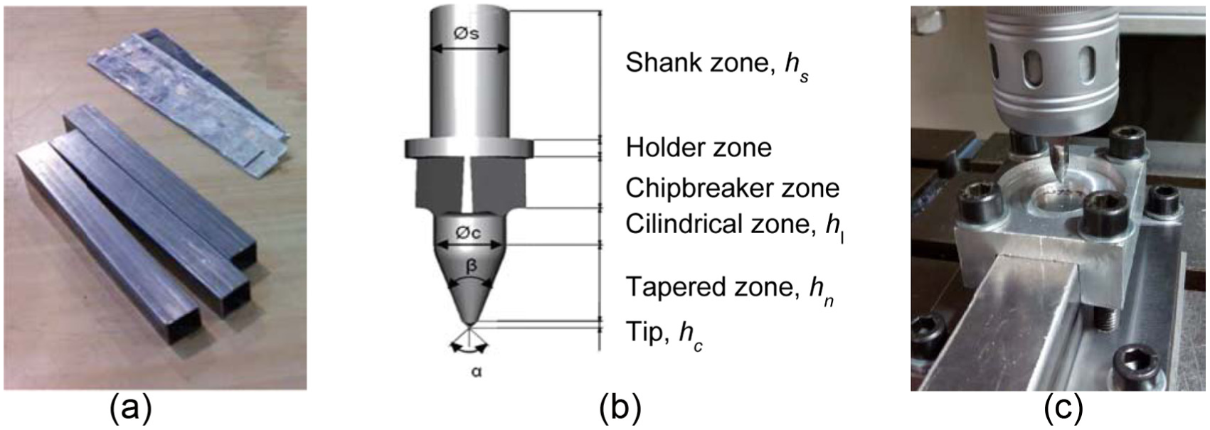
(a) Workpiece: sheets and tubes, (b) friction drilling tool, and (c) detail of the clamping fixture.
Three dissimilar joints were investigated, combining two types of common aluminium alloys with two types of steels (common AISI 1045 and 304 stainless steel):
Case A: square-section tubes (30 × 30) of AISI 1045 and sheets of Al 5754 (thickness = 1.5 mm).
Case B: square-section tubes (30 × 30) of stainless steel AISI 304 and sheets of Al 5754 (thickness =1.5 mm).
Case C: square-section tubes (30 × 30) of stainless steel AISI 304 and sheets of Al 6082 (thickness =1.5 mm).
Regarding FD tools, in all cases, carbide tools (90% WC and grain size 1 µm), ∅7.3 mm were employed for achieving M8 × 1.25. The main geometrical factors (see Figure 3) were as follows: hs = 15 mm, ∅ s = 8 mm, hl = 5.4 mm, ∅ c = 7.3, hn = 7.6 mm, hc = 0.9 mm, β = 40°, and α = 90°.
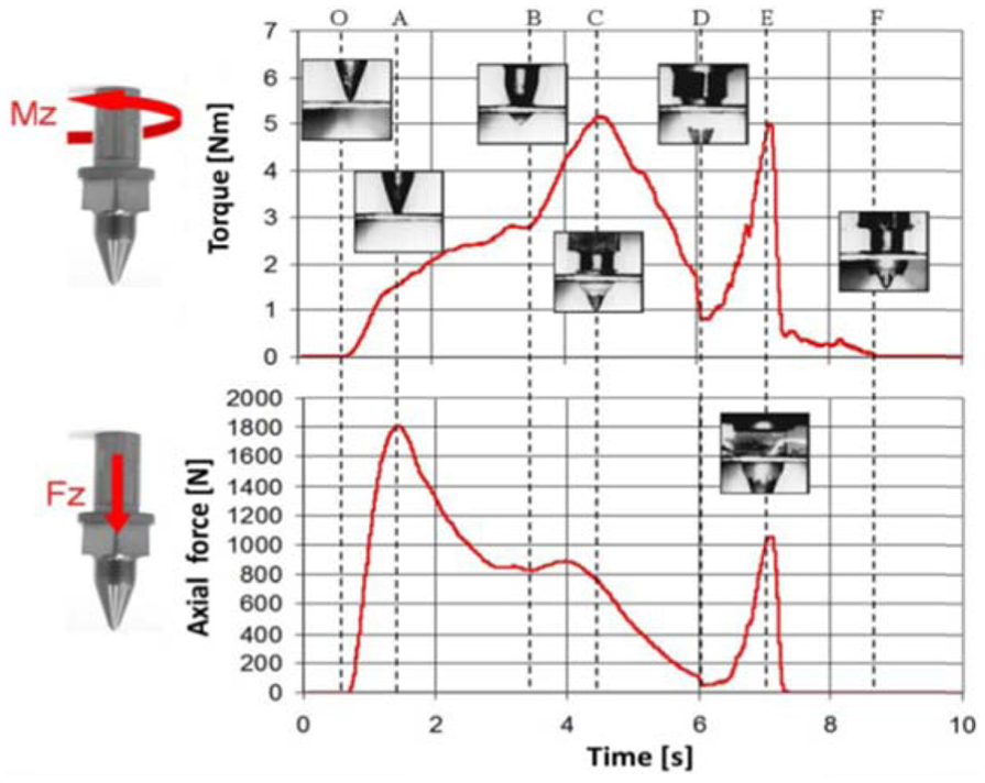
Evolution of force and torque in friction drilling.
A campaign of trials was designed to verify the influence of the two main parameters affecting the FD process: the spindle speed and the penetration (feed) speed. These parameters were swept from 1500 to 4500 r/min and from 150 to 500 mm/min, respectively. Throughout the process, online magnitudes (cutting force, torque, and temperature) and offline magnitudes (hole diameter, gap, and cup size) are measured to evaluate the best combination (fz, S).
Forces and torque
The force monitoring allows understanding of the friction mechanisms during the deformation process and the generation or rupture mechanisms of the upper side of the burr.34,36 To measure the thrust force and torque, an Artis© device based on strain gauges was used. It consists of (1) rotor, located at the toolholder; (2) stator, at 5 mm distance from the rotor; (3) transducer, which receives the load signal of the inductive sensor and converts it into voltage; (4) acquisition board, with a sampling frequency between 0 and 1000 Hz and data transfer capabilities to a PC via USB; and (5) notebook with Quick Data, for data recording. During the tests, a sampling frequency of 800 Hz was used. The signal was post-processed with MATLAB© to find the torque and average and maximum forces. Comparing to a Kistler© dynamometer where the centre of the hole and the Kistler table must be aligned, the measurements using Artis are simpler and direct because the acquisition is independent of the working point. Figure 3 points out the most relevant stages during the hole-making process:
OA: the central area of the tool (tip) rubs against the surface of the workpiece while advancing, and the thrust force increases.
AB: as the process progresses, the contact area between the conical tool tip and the workpiece increases, and thus, the friction and the associated torque start growing because the radius is increased.
BC: the cylindrical portion of the tool contacts the burr portion of higher thickness, resulting in a slight increase in the thrust force and rapid increase in the torque values.
CD: the torque decreases when the cylindrical portion of the tool starts to deform the burr region of lower thickness. The thrust force also experiences a steady decline.
OF: this region corresponds to the tool chip breaker area. The top burr is crushed by the tool resulting in higher torque and axial force.
EF: this region refers to the tool retraction. The thrust force decreases rapidly to zero, although there is a slight friction between workpiece and tool as shown by the measured axial moment.
This general trend is shared by all the three cases. Figure 4 shows the force and torque for case A specimens. Higher plate thicknesses (Figure 4(a)) will increase both the thrust force and torque, with a non-proportional augmentation at the tool exit. Due to a bigger volume of softened material, the contact area between the cup and the tool increases, and so, higher frictional forces and deformation resistance occur. For a constant spindle speed, the thrust force is propotional to the feedrate (Figure 4(b)). This is due to lower contact times between workpiece and tool, that is, less amount of heat is generated to soften the material. Finally, when the rotational speed increases (maintaining constant feed values), the thrust forces and torque decrease because more heat comes from the greater frictional time (Figure 4(c)).
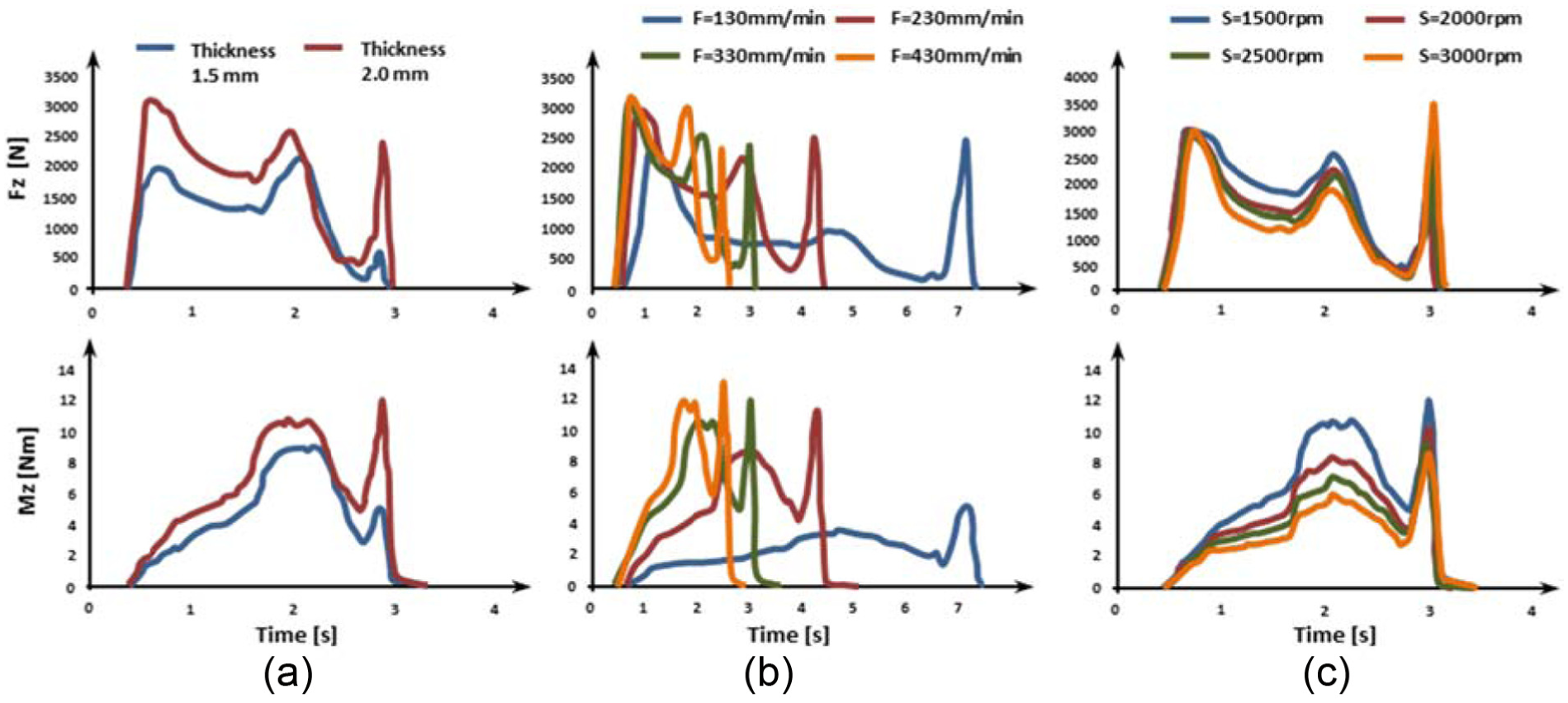
Evolution of force and torque in friction drilling (case A): (a) effect of plate thickness (S = 1500 r/min and F = 330 mm/min), (b) effect of feed rate (S = 1500 r/min), and (c) effect of spindle speed (F = 330 mm/min).
Temperature
The temperature reached by the workpiece is an important factor for a correct cup formation. When this value is low, the chip is prone to fractures and tends to remove the material radially to the hole. However, when the temperature is high, the cup has a cylindrical shape, but thermal distortion can appear during cooling.37,38
In this case, the temperature was recorded using a two-colour pyrometer (Impac© IGAR 12 LO, with measuring range from 350 °C to 1300 °C) that points towards tool exit (Figure 6). The signal was captured in real time using a computer and specific software.
The heat is first generated by pure friction. Then, the tapered zone also increases heat generation due to friction and plastic deformation of the material. The cooling rate of the material after machining is also important as it determines the microstructural transformations. The maximum temperature affects the quality of the generated cup. If low, brittle cups are observed, while higher temperatures lead to cylindrical shaped ones (more suitable for threading). The maximum temperature is dependent on the rotational speed and tool feed. When increasing the rotational speeds, higher friction between tool and workpiece occurs, leading to high process temperatures (Figure 5). However, the maximum temperature at the tool exit is quite similar for all the spindle speeds. However, the increase in the feed rate results in a decrease in the maximum temperature since the contact time between tool and workpiece decreases.
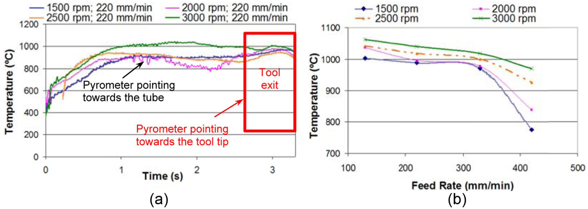
Temperature evolution with time: (a) influence of spindle speed and (b) influence of feed rate.
Hole quality
In conventional drilling with twist drills, the hole diameter diminishes due to tool wear. On the contrary, in FD, just the opposite is experienced because of the progressive adhesion of the work material onto the tool bit surface.
The hole quality can be studied by means of five parameters; first, input diameter Din (on the top plate of aluminium) and output diameter Dout (on the tubular steel); second, by measuring the gap created between the two components (Pt and Pc in Figure 6) and the cup thickness. The gap can cause differential aeration of the joint and must be as small as possible because it causes metal corrosion as a result of the formation of an oxygen concentration cell, due to an uneven supply of air on the metal surface.
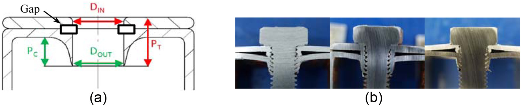
(a) Characterization of hole quality and (b) gap area in friction drilling (cases A, B, and C).
Figure 7 shows the variation in the hole diameter based for case A (AISI 1045-Al5754). While it is observed with consistency between both diameters, smaller values for the output diameter lead to slightly tapered holes.
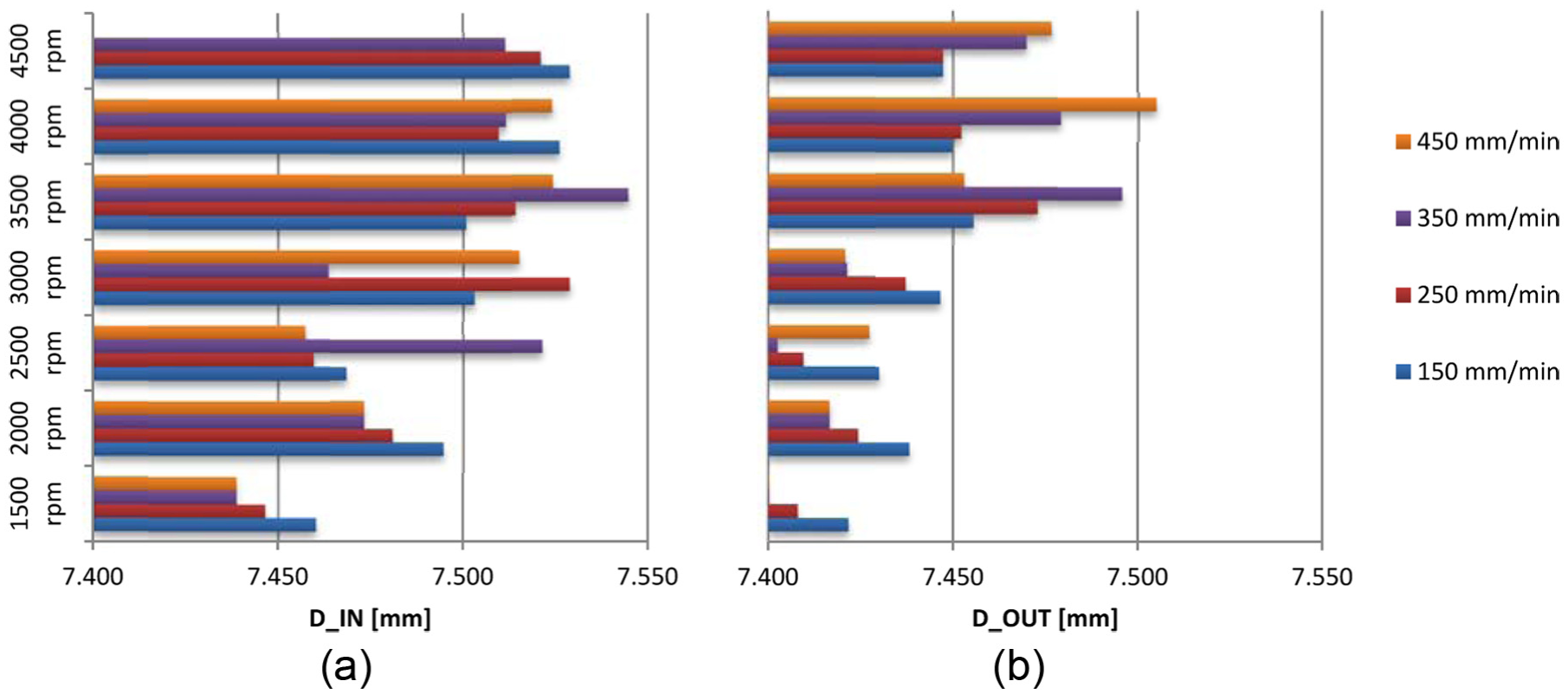
(a) Input and (b) output diameters against cutting conditions.
Using the indirect measures of Pc and Pt parameters, the gap may be calculated (Figure 8). From this plot, high spindle speeds and low feed rates are the best combination to achieve a minimum gap (MG).
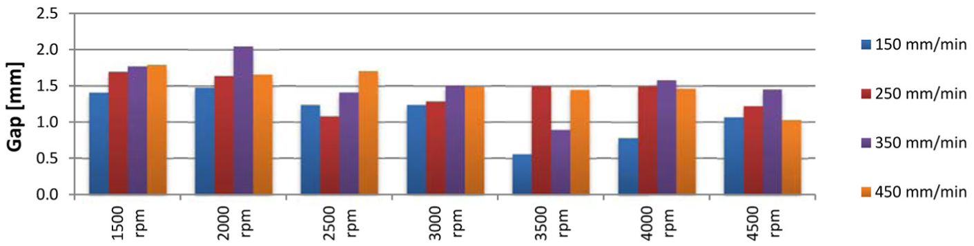
Gap between sheets against cutting conditions (case A).
The cup size defined on the total depth and cup thickness is affected by the choice of the drilling parameters. A cross section of the holes was done in order to measure consistently and accurately the burr shape. To characterize the thickness of the burr, a microscope, Mitutoyo© TM-100, was used. It is equipped with 2-µm heads to ensure accurate positioning and adjustment. The measurements were chosen at different heights in the vertical axis (Figure 9). From them, it follows that higher feed rates cause an increase in the burr thicknesses along its entire length favouring subsequent threading operations.
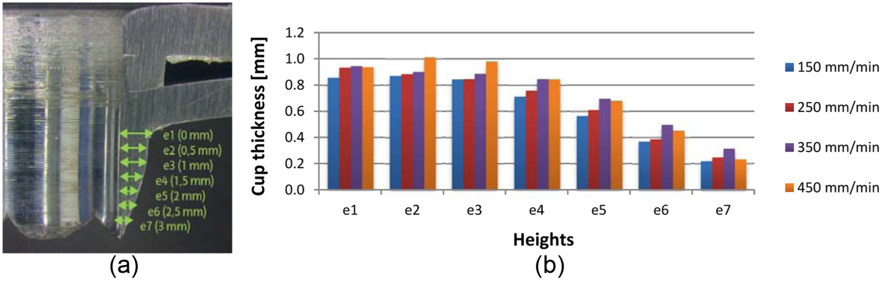
(a) Measurement at different heights and (b) cup thickness at S = 3000 r/min.
Relationships between main parameters and basic criteria
As a summary of preliminary results in section ‘FD’, Table 1 represents some of the main relationships between the input (I) and the output (O) variables. The output variables are sub-divided into (1) online magnitudes (force, torque, and temperature) and/or (2) offline value, related with hole quality. Increasing the spindle speed is advantageous for achieving lower cutting forces and torque for an MG but leads to higher deviations from the nominal diameter. However, either decreasing the feed rate or increasing the plate thickness will increase the tool–workpiece contact times (i.e. the temperature).
Influence between input (I) and output (O) parameters.
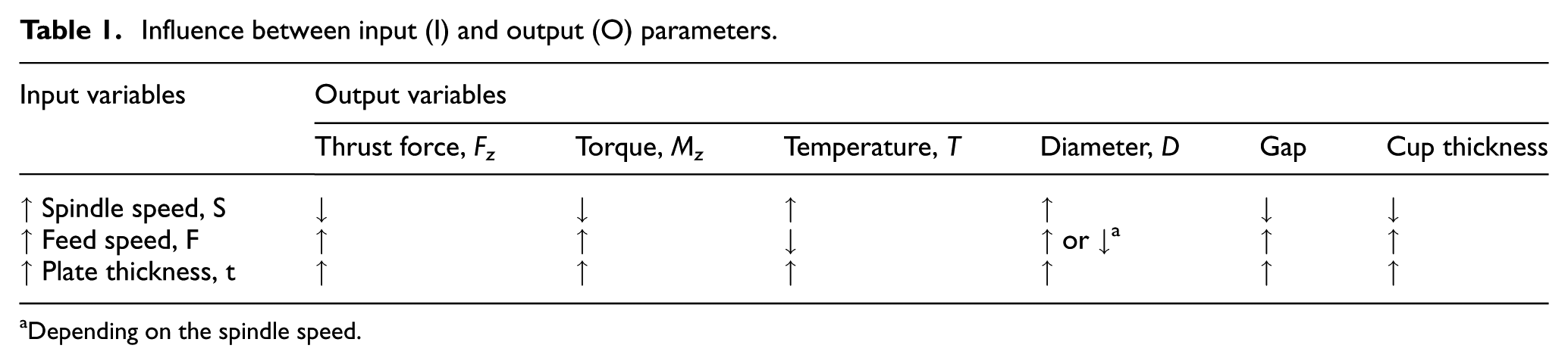
Depending on the spindle speed.
So, depending on the objective, there are several criteria depending on which objective do we have:
MG: the smaller the gap between sheets, the lower the exposure that the metal will have to the environment, thus improving its corrosion resistance. The parameters giving the MG in AISI 1040-Al5754 were as follows: F = 150 mm/min and S = 3000 r/min.
Optimum diameter (OD): the OD is defined from the standard DIN 13. These parameters are as follows: F = 250 mm/min and S = 2500 r/min.
Maximum cup thickness (MCT): a large cup or burr thickness make easier and stronger the next stage of FT, resulting in F = 450 mm/min and S = 3000 r/min.
Additionally, the typical drilled by twist drill bolted joint with nut is also considered, referred with capital letter BJ (after bolted joint).
FT
Subsequently, the hole needs to be threaded by FT. Regarding the tool, taps are often polygonal geometries with at least five lobes. Taps are made of high-strength steel (HSS) coated with titanium nitride (TiN) to provide a core with enough toughness but harder surface. In some cases, anti-friction coatings or internal lubrication are advisable. Also, they may include tapered cutting edges with smaller diameter to initiate the material removal. According to the hole machined with the ∅7.3 form tool, a form tap (Emuge©) for M8 was selected.
In FT, the maximum depth of the thread and the maximum thread pitch are the most important parameters (Figure 10). An FT is characterized by (1) the entrance zone, at the tool tip, which is a tapered geometry where the lobes progressively increase the nominal diameter (ISO 8830), and (2) the cylindrical part, which acts as a supporting system, guiding the tap during threading operation. The maximum depth of thread is significantly higher than in the case of conventional threading (cutting) tools, being limited by the quality of the coolant and the tool length. The maximum pitch of the thread depends on the material properties of the workpiece. The upper limit is often below 3.5 mm. Indeed, not all the materials are suitable for FT, that is, due to the intrinsic deformation involved, the material should have a minimum ductility (minimum failure resistance at 5%) and should not exceed a maximum mechanical resistance of 1400 N/mm2.
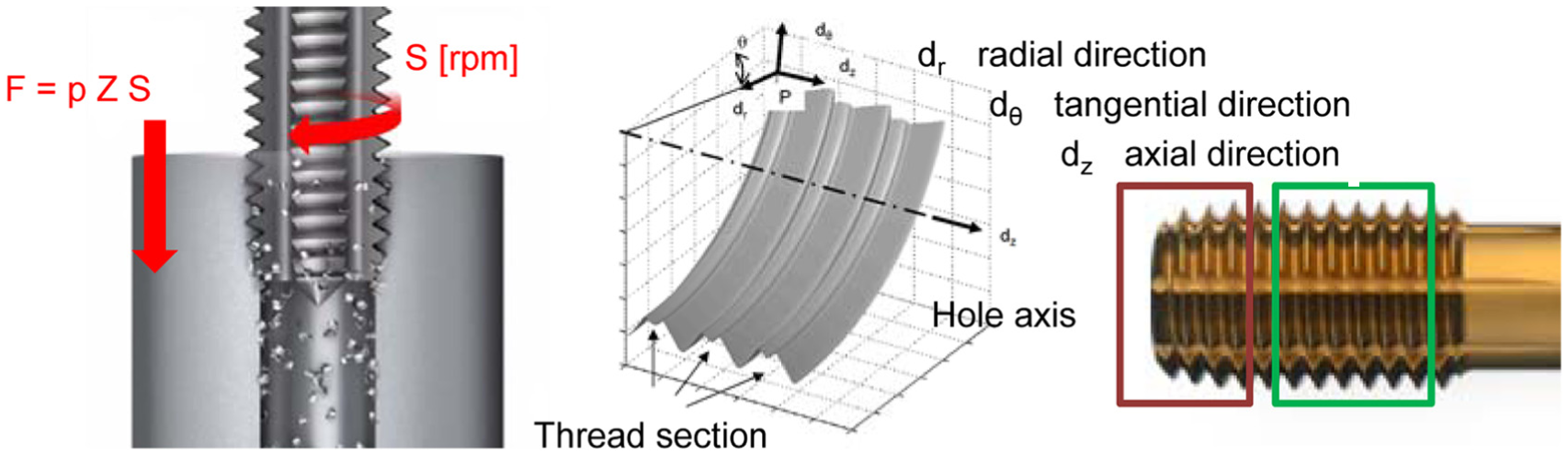
FT: thread operation, thread section, and tap geometry.
Another important aspect is the influence of the pre-machining diameter. Too small diameters will lead to excessive rolling phenomena and forces during the process. Inversely, if this diameter is too large, the core section is not enough rolled, and the core diameter will be too small.
Regarding possible changes in the material, due to deformation mechanisms, work hardening may also arise in the affected zone. This phenomenon is accentuated the greater the wear. Additionally, since there is crushing and deformation, internal compressive stresses appear which are advantageous to enhance the mechanical resistance of the thread.
As in the previous section, a test series was designed to select the most suitable cutting parameters for consistent thread through hole trials’ rolling friction generated by drilling. To do this, the same clamping system referred in section ‘Analysis of part quality’ was employed (Figure 11(a)). The use of an absolutely rigid toolholder was considered risky due to the non-perfect synchronization between the spindle rotation and the linear feed because tap must follow the inverse spiral path during extraction. Preliminary tests make this option not recommendable due to the poor repeatability of the operations.
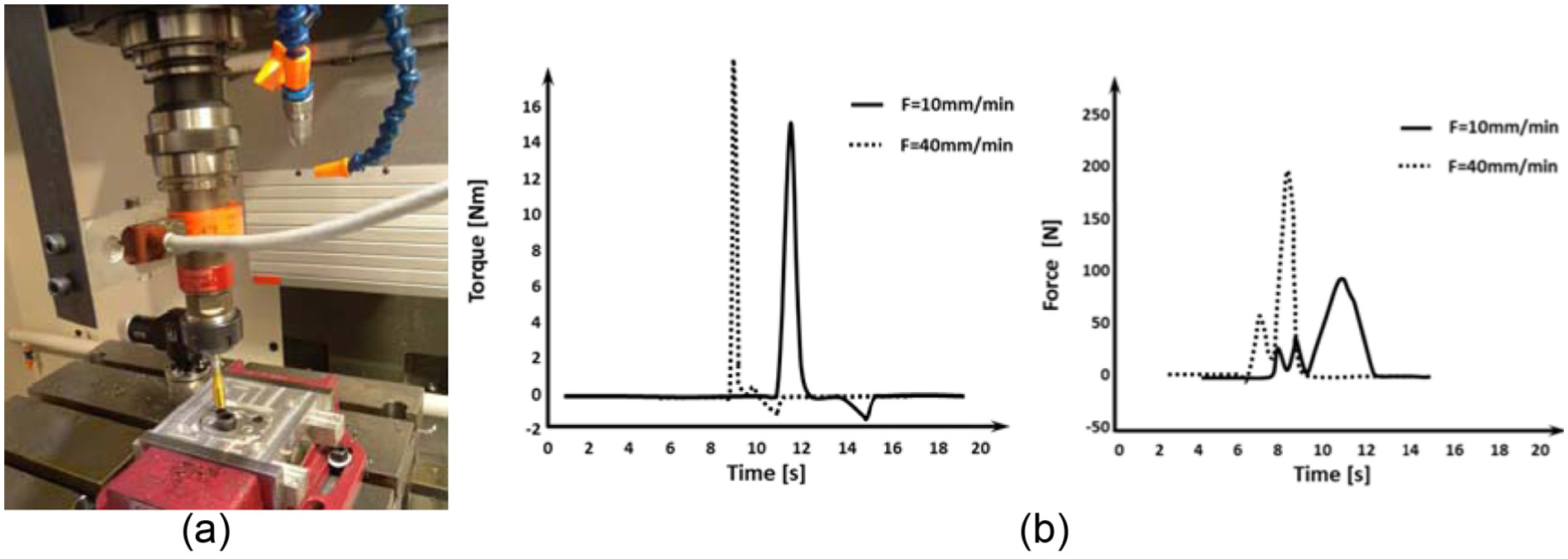
Form tapping (a) experimental set-up and (b) torque (left) and thrust (axial) force (right).
For the threading cutting tests, different feed rates (10–40 mm/min) were conducted at constant spindle speed (600 r/min), recommended by the tool manufacturer. Figure 11(b) shows the values of torque and force for the extreme cases. As a conservative criterion, the criterion with the lowest feed rate was chosen since it generates a low amplitude and damped peak.
Analysis of part quality
In this section, the main results from the mechanical and corrosion tests are depicted. To evaluate the joint properties, micro-hardness analysis and shear cutting tests were performed. Then, a series of salt spray tests was done to verify qualitatively the corrosion of the specimens.
Micro-hardness measurements
The hardness study involved two stages: first, the difference in hardness between the deformed and undeformed zones was analysed for the three couples of materials. Second, the difference in the hardness along the z-axis of the hole was quantified for the pair AISI 1045-Al5754, for the three criteria: OD, MCT, and MG. Similar behaviours are expected for the other two specimen types.
Vickers hardness tests were performed according to norm UNE EN6507-1 in sections of specimens of AISI 1045-Al5754 and AISI-304 with Al5754 and Al6082, with MG condition. All the tests were done using a hardness meter (Vickers micro-hardness FM-800) focusing on points located at the undeformed and deformed zones of the tube (steel) and plate (aluminium). As seen in Figure 12, the hardness in the steel tube increases in the deformed region. On the contrary, the hardness values for the aluminium sheets decrease in the deformed areas. The measurements were found to be consistent as it can be deduced from the measurements from the materials shared, AISI 304 and Al5754, with maximum absolute errors below 5%.
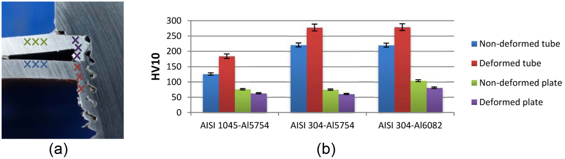
(a) Test areas for hardness measurements (tube and plate) and (b) Vickers hardness measurements for different pair materials (MG condition).
Additionally, three samples of AISI 1045-Al5754 were taken to perform micro-hardness studies of the materials along the vertical axis of the joint (Figure 13). To do this, three samples corresponding to the three criteria set out in section ‘Analysis of part quality’ were encapsulated and polished: MG, OD, and MCT. In all cases, the transition from aluminium to AISI 1045 steel is observed, with a greater hardness in the case of maximum burr thickness condition and lower hardness in the case of MG. The results were consistent with each other, with similar relative increases in the steel hardness and decreases in the aluminium hardness with respect to their respective initial values. Again, the maximum deviations from the mean value were about 7% at the worst case.
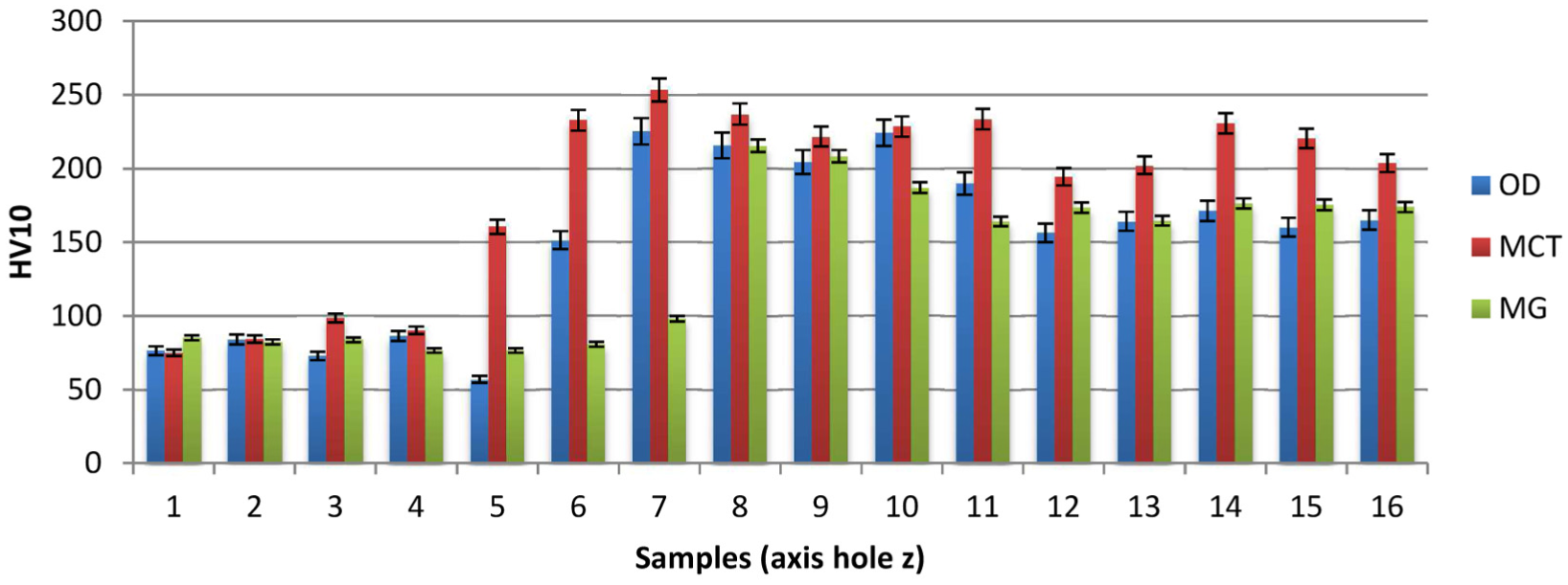
Micro-hardness for the three criteria.
Mechanical resistance
To characterize mechanically the joints, shear tests were carried on case A specimens with two objectives: first, to compare the ultimate strength for the three criteria; second, to study the failure modes of the machined parts. Either from FD process (OD, MCT, and MG) or from conventional drilling (BJ), the joint assembly was completed using steel screws.
The shear tests were performed with three testing samples per criterion in a universal testing machine, pulling the two sheets from opposite-coaxial jaws so that the screw suffers pure shear stress. As a result, the type of failure is obtained and the maximum force recorded. A priori, the possible mechanisms could be (1) failure of the joint between materials (at the interface), (2) failure of the softest material (aluminium), and (3) screw breakage.
Table 2 depicts the maximum loads (averaged from three samples) and the corresponding failure mode for each of the types. The failure mode classification is selected according to the criteria in the Metallic Material Properties Development and Standardization (MMPDS-01).
Results of the shear cutting tests.
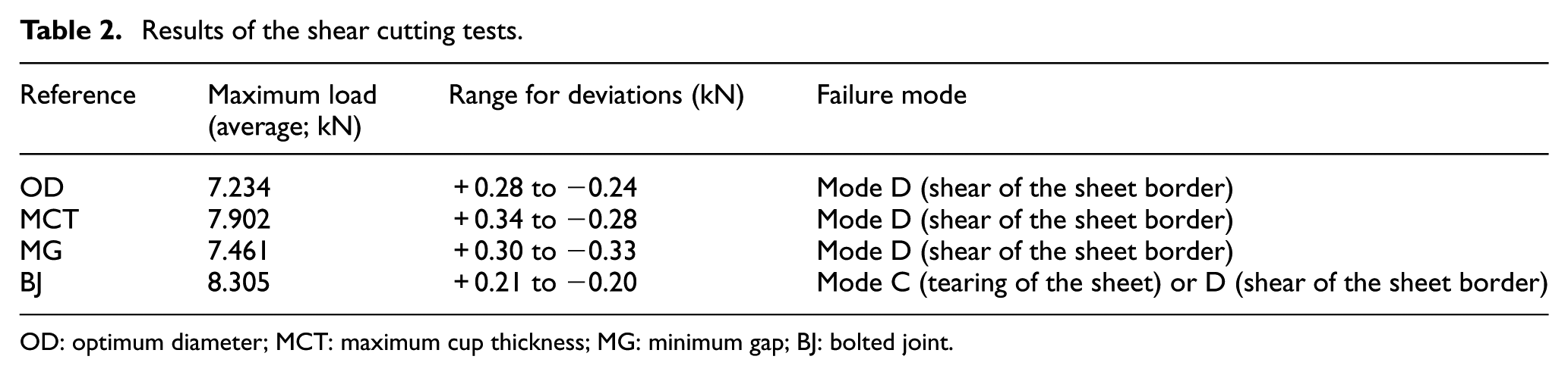
OD: optimum diameter; MCT: maximum cup thickness; MG: minimum gap; BJ: bolted joint.
In all cases, the shear mechanical resistance was limited by the mechanical strength of the aluminium. However, the MCT condition seems to be the best choice, that is, the nearest from BJ condition. Table 3 shows the final states of the joints after the failure together with the corresponding load versus displacement graphs. Only the graphs associated with case A are plotted because similar graphs and consequences are extracted for case B.
Final state of the test parts and load–displacement graphs.
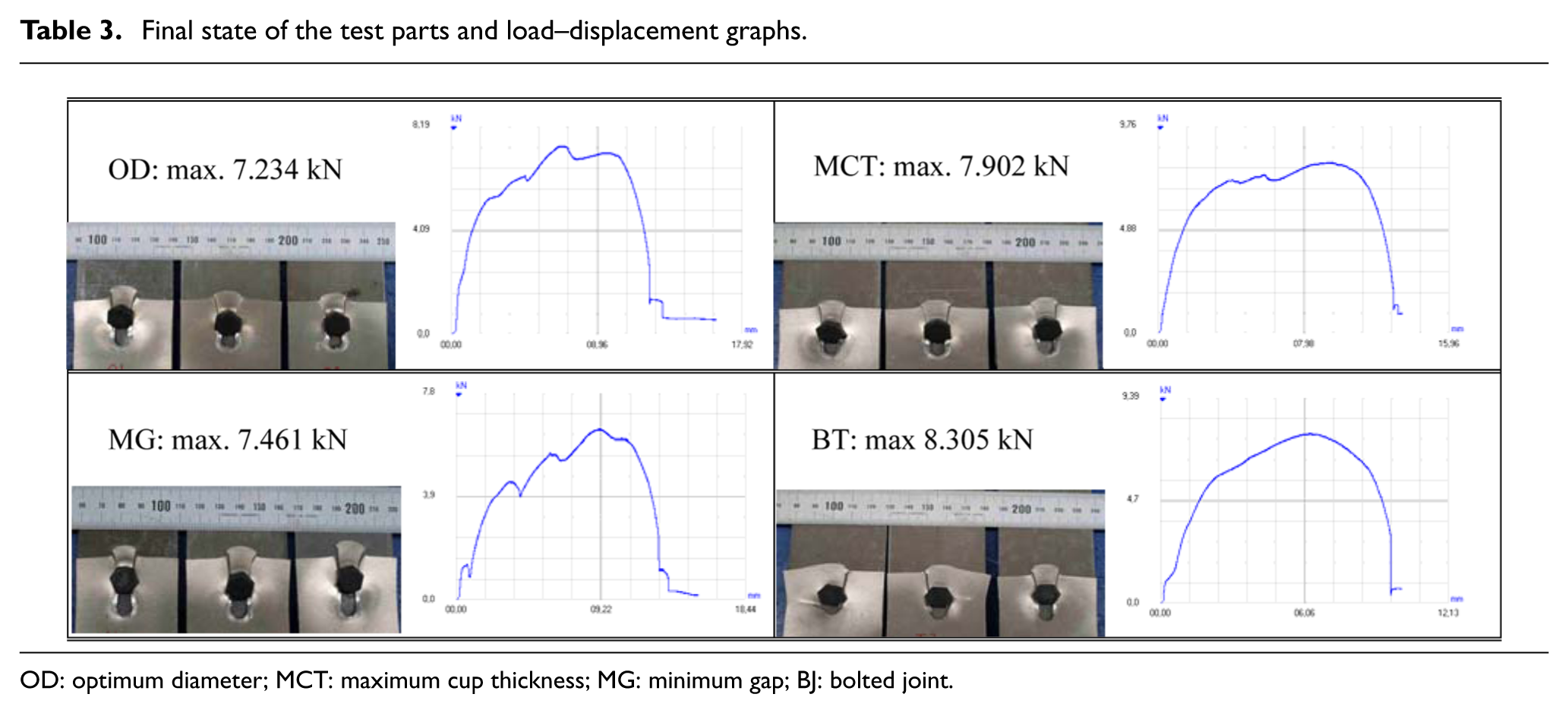
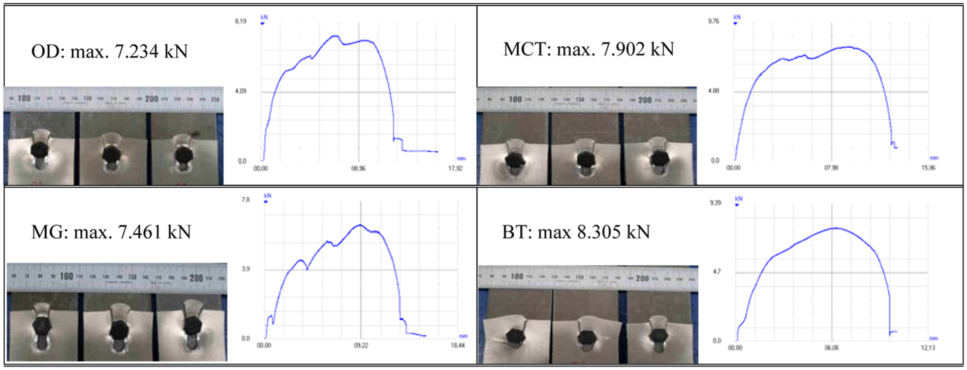
OD: optimum diameter; MCT: maximum cup thickness; MG: minimum gap; BJ: bolted joint.
Galvanic corrosion
When dissimilar materials are put to work in a dry atmosphere (or more general, in non-electrolyte media), nothing occurs. However, if the same equipment contacts electrolyte (salts solutions, acids, or alkalis), corrosion of the less noble metal (a metal with less electrode potential) will occur. Such type of corrosion is called galvanic or dissimilar metal corrosion which is influenced by environmental, electrochemical, metallurgical, or geometrical factors. These can be resumed into three main factors: the difference of electrode potentials of various metals and alloys, the ratio between anode and cathode areas, and the electrical conductivity of media. The greater the difference of electrode potentials between dissimilar metals, the more severe the galvanic corrosion.
The salt spray (or fog) test is a standardized and popular corrosion test method, applied to several dissimilar joints following the guidelines of ISO 9227 Corrosion tests in artificial atmospheres – salt spray tests, 2006 (salt type: 5% NaCl/95% distilled H2O, temperature in the cabin: 35 °C, salt spray recovery speed: 1.2 mL/h, pH of the recovered salt fog (25 °C): 6.7, and density of the recovered salt fog = 1.031 g/cm3). It is important that the specimens were placed at a certain angle to facilitate the saline attack over the surface. As a matter of fact, the purpose of this testing was to understand the behaviour of joints in severe atmospheres. In this case, two specimens were analysed for each case in Table 4.
Results: corroded surface in percentage (from the total surface).
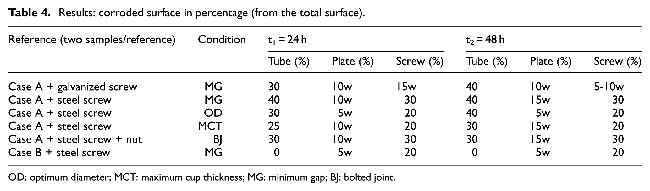
OD: optimum diameter; MCT: maximum cup thickness; MG: minimum gap; BJ: bolted joint.
The tests ended at t2 (48 h) due to the occurrence of iron rust in most elements. First, the specimens were cleaned with a brush to remove salt and corrosion products. Then, the presence of surface rust on the various elements of the specimen (tube, plate, and screws) was observed. The results of the corrosion test at times t1 = 24 h and t2 = 48 h are shown in Table 4 showing the percentage of the entire surface of the elements having iron corrosion (reddish). White rust, for aluminium or galvanized steel, is indicated with ‘w’ (Figure 14).
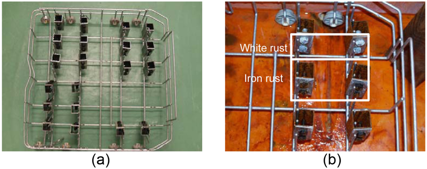
(a) Specimens inclined in support and (b) specimens after 48 h in the fog.
Concerning the corrosion and case A, no appreciable differences were observed between the test pieces with different manufacturing conditions (OD, MCT, and MG). All aluminium sheets suffered white corrosion at time t2. Except case B, the other specimens and the screws (galvanized and steel) suffered iron corrosion after 48 h of testing.
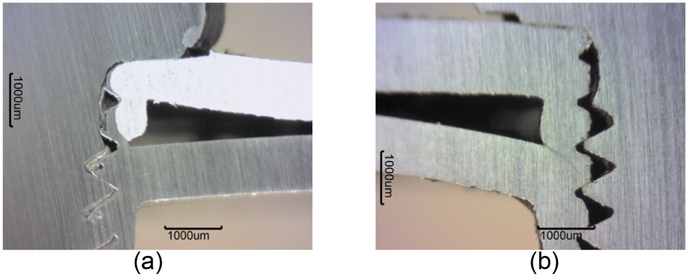
When removing the screws of the specimens, it was observed that case A was easier to disassemble than case B. Due to the presence of screws, electrochemical corrosion also occurred. The difference in the concentration of ions made the solution becoming stagnant leading to crevice corrosion (Figure 15). This effect is due to localized depletion of dissolved oxygen in the vicinity of the burr.
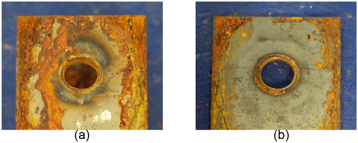
Details of crevice corrosion: (a) tube and (b) plate.
From the examination of the probes at the mean section, it was observed that the plate was curved and welded with the tube serving as a base for the future thread (Figure 16(a)). This effect occurred for all the combinations of specimens. Figure 16 shows the difference between a suitable welded union and incorrect union (no welding) leading to a low-quality thread between steels (not studied here).
(a) Welded union between plate and tube necessary for a suitable thread (case B) and (b) union without connection between plate and tube (AISI 1045 and 1020).
From these results, a second series of tests was done specifically on case B with stainless steel probes. These are coded as follows: OD1 = OD (with screw), OD2 = OD (without screw), MG, and MCT. Table 5 shows the results of each specimen in detail, with the percentage of the corroded surface. The following notation was used: ‘–’, ferric corrosion; ‘w’, white aluminium corrosion (loss of metallic bright and pitting); and ‘b’, brown-coloured corrosion: observed in zones contaminated from near rusted elements. The tube–screw interface was noted as ‘ts’.
Results: corroded surface in percentage (from the total surface).
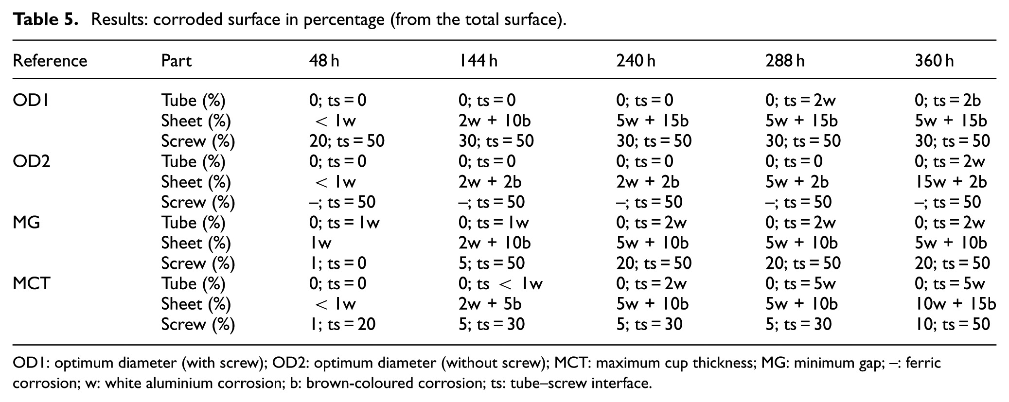
OD1: optimum diameter (with screw); OD2: optimum diameter (without screw); MCT: maximum cup thickness; MG: minimum gap; –: ferric corrosion; w: white aluminium corrosion; b: brown-coloured corrosion; ts: tube–screw interface.
All the specimens of case B are corroded at t = 144 h on the aluminium sheets. The tubes and screws are not affected, but slight-reddish colouration is observed at the screw heads, near the cup (tube–sheet interface). Among all the specimens, a lower degree of corrosion is observed on the plates with MG condition. Concerning the MCT specimens, these do not generate burr at the tube, thus causing a weaker union.
Then, the metallographic inspection of the corroded aluminium sheets was performed. Figure 17 shows the corrosion pits due to the retained salt. The maximum pitting depth (0.3 mm) was found at the inner surface of the sheets. This accelerates the corrosion process, so it limits the application of the process in harsh conditions.
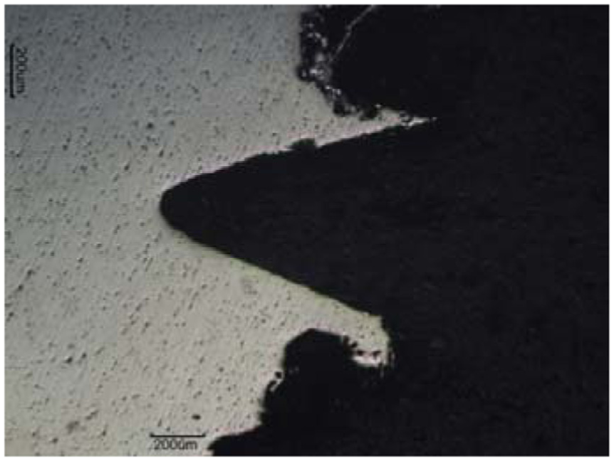
Pits on the probe with MG condition.
Conclusion
This article proposes a novel approach, based on the combination of FD and FT, for joining sheets and tubes made from dissimilar materials. First, both processes were studied and monitored to obtain the most performing conditions (according to different quality criteria). Suitable values for the rotational speed and feed were defined for both processes. Second, the mechanical behaviour of the new joints was verified against common bolted joints made with conventional drilling. From the mechanical tests, it was deduced that the new joints have similar properties and collapse under similar stress thresholds than the ones made by traditional cutting processes. Therefore, comparing to classical bolted unions (that use conventional drilling and require nuts), the presented technique offers not only a cleaner solution (less chips and lubricants) but a reliable option with comparable mechanical properties. In the case study, the test tubes broke down due to the collapse of the softest material. Some of the most important results are as follows:
In the least favourable case, the mechanical strength of the joint by FD + tapping represents 87% of the typical resistance by conventional drilling + threading.
A similar corrosion behaviour is seen on the different kinds of specimens (OD, MG, and MCT) for cases A and B. The specified cutting conditions do not seem to affect the service life of the specimens.
The steel tubes gained higher hardness in the deformed areas. This is not true for the adjacent zones of the aluminium sheets whose hardness values decrease with respect to the properties of the material base.
For the specimens type A, the aluminium sheets suffer white corrosion after 48 h. The AISI 1045 tubes suffer iron corrosion after 48 h of operation, while AISI 304 stainless steel presents a good aspect.
As a major drawback, the FD process causes a separation between the tube and the sheet. This allows the accumulation of moisture and salt leading to crevice corrosion and pitting that reduce the service life of potential products in adverse conditions. This determines the field of application of the product.
For aggressive conditions, the pair Al5754-AISI 304 is recommended with the MG condition to delay as much as possible the corrosion onset. Coating countermeasures will also be advisable in this case.
Footnotes
Acknowledgements
The authors thank UFI 11/29 in Mechanical Engineering of the UPV/EHU for its support to this project and CiC marGUNE (Etortek ESTRATEUS). In addition, the authors gratefully acknowledge the advice of I. Azkona and J. Fernández from Metal Estalki as well as to the former student Deividi Nardi.
Declaration of conflicting interests
The author(s) declared no potential conflicts of interest with respect to the research, authorship, and/or publication of this article.
Funding
The author(s) received no financial support for the research, authorship, and/or publication of this article.