
Abstract
The logarithmic spiral bevel gear is a new type of spiral bevel gear and has received great attention in the industry for its excellent engineering characteristics. The objective of this study is to develop an accurate geometric model for the logarithmic spiral bevel gear. Based on the gear tooth flank formation mechanism, a conical logarithmic spiral curve with a constant spiral angle was constructed as the tooth trace curve. The profiles for the exterior and interior transverse of the tooth were built with an accurate involutes curve, with transition being circular arcs and straight lines. The first tooth model was established by sweeping the tooth profile accurately along the tooth trace curve, and the rest of the teeth were created by an array operation. The accurate three-dimensional model of logarithmic spiral bevel gear was finally obtained by means of a Boolean addition operation among all of the gear teeth and the root cone. An experimental study was carried out for such a gear whose number of teeth was 37, with modules being 4.5 mm, normal pressure angle being 20° and spiral angle being 35°. A DMU 40 monoBLOCK five-axis computer numerical control milling machine tool was used to produce the prototype, and a Zeiss CONTURA G3 three-dimensional coordinate instrument was employed to measure the exterior transverse addendum diameter. The linear error between the theoretical model value and the measured average value was 0.0027 mm, indicating the effectiveness and practicability of this modeling method, which provides an accurate geometric model for design and for subsequent tasks like computer-aided engineering analysis and manufacturing.
Keywords
Introduction
Spiral bevel gear (SBG) with the premium advantages of stable transmission, low noise characteristics and high coincidence ratio is widely used in aerospace, machine tool, shipbuilding and automobile industries. 1 The varying spiral angle in conventional SBG directly affects the stability of transmission, the contact state of tooth surface and the service life. One of the basic requirements for SBG meshing is that the spiral angle of meshing contact point at a point needs to be equal. A large number of parameters of the cutters and machine tools need to be adjusted for the manufacture of SBG because of the different spiral angles at a point on the tooth trace curve, and even so, it cannot ensure the spiral angle to remain a constant from point to point. A new type of SBG, known as logarithmic spiral bevel gear (LSBG), has been proposed in the literature,2,3 with characteristic of constant spiral angle because the tooth trace curve is a conical logarithmic curve. Although the new type of SBG is advanced in theory, the actual effects in the process of design, manufacturing, assembly and computer-aided engineering (CAE) analysis still need to be researched and verified. 4 Therefore, the primary problem for the next series research is to establish the accurate three-dimensional (3D) geometric model of LSBG.
The modeling technology for conventional SBG is becoming more and more matured5–9 and the technology is already built into commercial software packages, such as UG NX after version 7.5 coming with a GC Toolkit and Solidworks 2011 with Geartrax toolbar. Generally, there are mainly two methods for the modeling of conventional SBG.10–13 The first method is fitting modeling based on tooth surface equation differentiation.14–16 The tooth surface model is generated by fitting the discrete points on the tooth surface which is solved by the data processing software tools (such as MATLAB, Mathematica, Maple, Excel and Access), and the model of SBG is generated from the tooth surface model in the end.17–21 This modeling method needs high mathematical requirements, the operation switches among multiple software tools is relatively tedious and the modeling accuracy is limited because of the interpolation error during discretization and fitting.22–26 The second method for conventional SBG modeling is the virtual simulation process modeling based on virtual processing technology.27–30 The SBG model is generated by making use of the virtual machine tools for 3D virtual simulation processing on semi-finished product of SBG model.31–34 This modeling method with the good advantage of consistency between the model and the actual processed prototype reflects the effect of processing. The apparent drawback of this modeling method is the system error between the 3D model and the mathematical model which influences the modeling precision.
There are few reports on the modeling of LSBG at present. Li and Yan
1
built a LSBG model with two deficiencies, one is that the transverse tooth profiles just are the projections of the normal surface involutes tooth profiles, which lead the size of face width b is difficult to ensure, and the other is that the top clearance coefficient C* = 0.7 and addendum coefficient
The derivation of conical logarithmic spiral curve equation
The constant spiral angle spiral curve formed on a cone (the ratio between curvature and torsion is a constant) is called conical logarithmic spiral curve as shown in Figure 1. To form such a curve, let a point M move on the cone surface. When the point moves from M0 to M1 with a turning angle τ on the cone surface, the angle will have a change from τ to τ + dτ when it approaches M2 from M1, and the vector

where a is the distance from the start point of conical logarithmic spiral curve to the cone top point O, φ is an independent variable (a projection angle on the bottom surface of turning angle of point M), α is a half cone angle and β is the spiral angle.
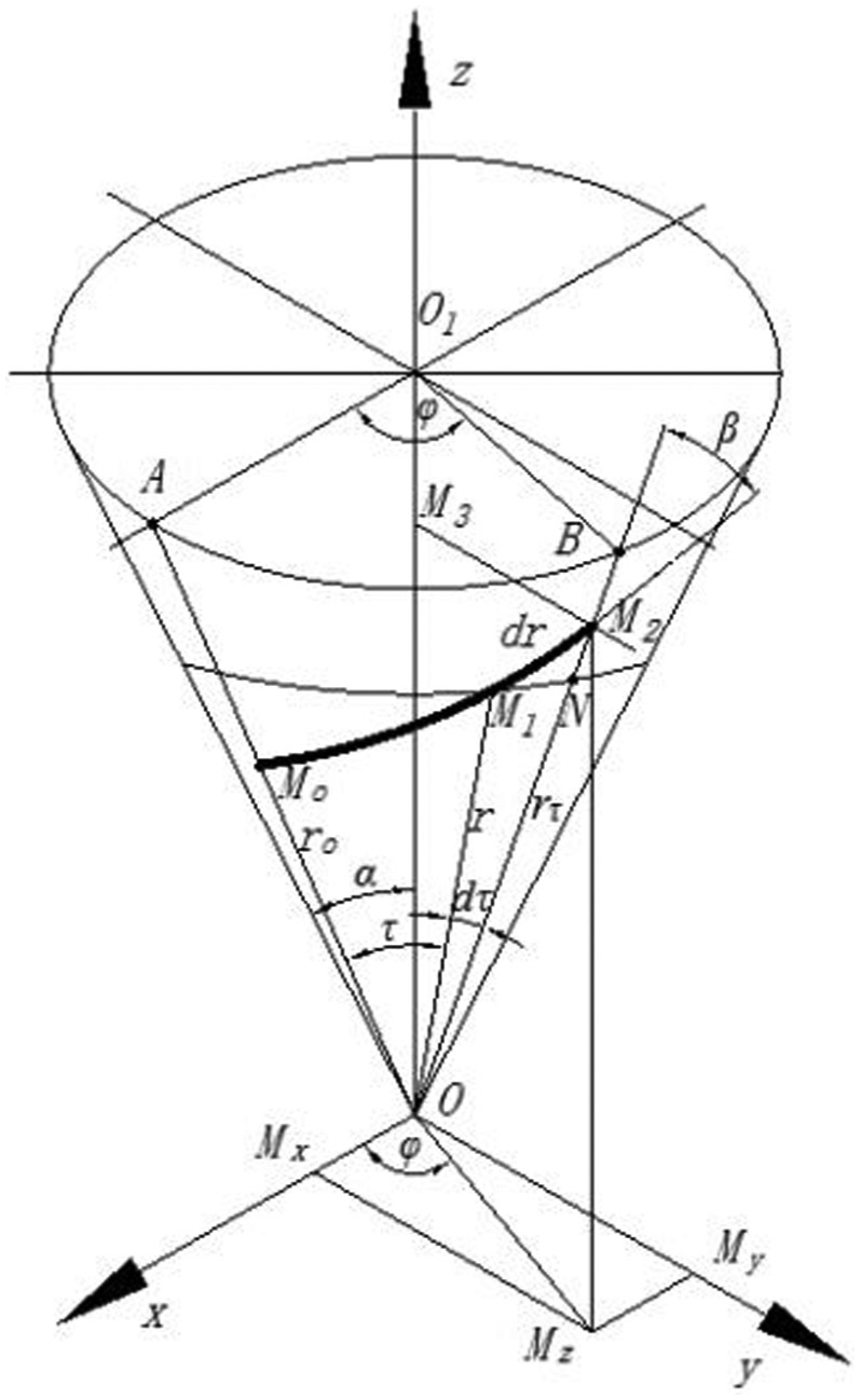
The conical logarithmic spiral curve.
Equation (1) can be rewritten in the form of parametric format as follows
The LSBG tooth trace curve is the conical logarithmic spiral curve. One of the important characteristics of conical logarithmic spiral curve is the spiral angle β at a point defined between curve tangent direction and the cone generatrix line direction is a constant. The spiral angle β is a constant as shown in Figure 1.
The accurate modeling of LSBG based on Boolean addition operation
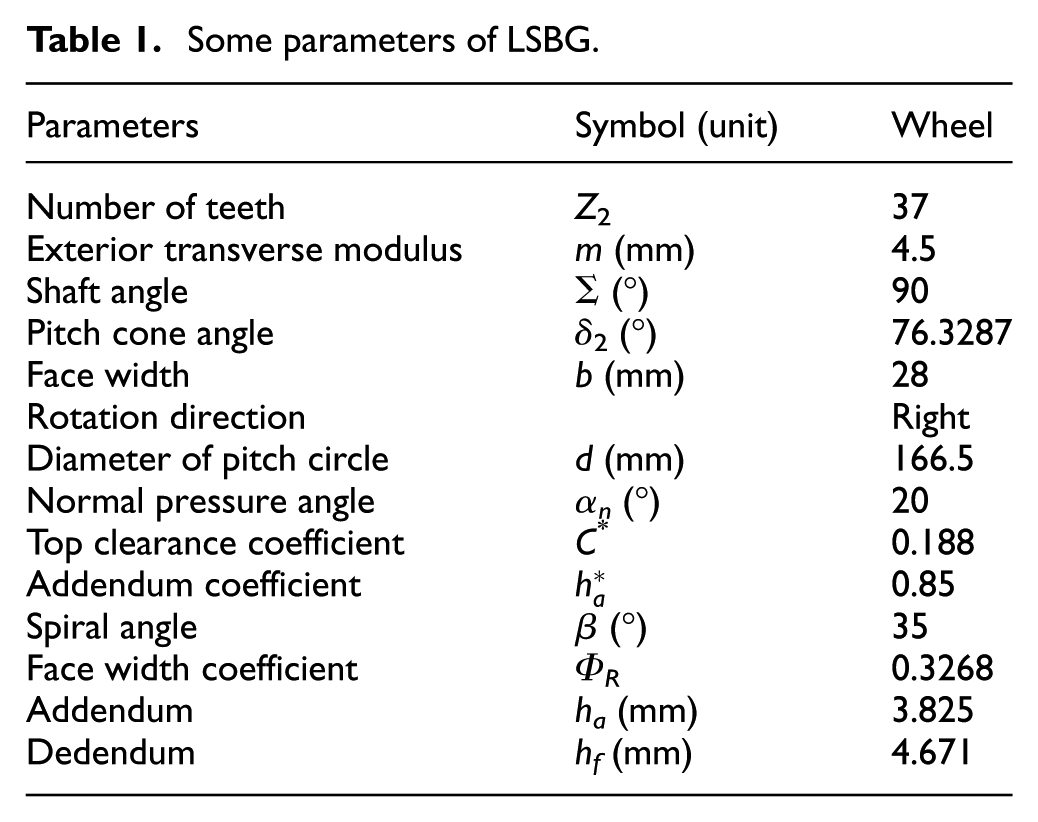
Some parameters of LSBG
There are a pair of conventional Gleason SBG which are installed on a mini bus main reducer. Replace the conventional Gleason SBG with LSBG.
Creation of the basic curves of LSBG
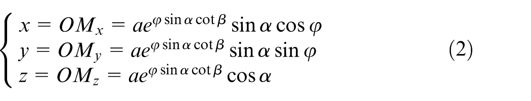
The basic curves of LSBG include the axis line of the wheel, the generatrix line of the face cone, the generatrix line of the pitch cone, the generatrix line of the root cone, the generatrix line of the base cone, the generatrix line of the back cone and the generatrix line of the front cone. The radius of the addendum circle is the distance from the generatrix line of face cone on exterior transverse plane to the axis line of the wheel. The radius of the pitch circle is the distance from the generatrix line of the pitch cone on exterior transverse plane to the axis line of the wheel. The radius of the dedendum circle is the distance from the generatrix line of the root cone on exterior transverse plane to the axis line of the LSBG. The radius of the base circle is the distance from the generatrix line of the base cone on exterior transverse plane to the axis line of the wheel. The basic curve relationships of the LSBG of exterior transverse can be deduced as follows according to the geometric relations
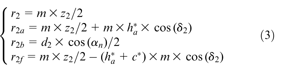
where r2 is the radius of the exterior transverse pitch circle of the LSBG, r2a is the radius of the exterior transverse addendum circle of the LSBG, r2b is the radius of the exterior transverse base circle of the LSBG, r2f is the radius of the exterior transverse dedendum circle of the LSBG, δ2 is the pitch cone angle of LSBG, Z2 is the number of teeth of the LSBG,
The basic curves.
According to equation (3) and the values of parameters in Table 1, we can obtain the specific value of a parameter in equation (3) and thus can draw the basic sketch curves of the LSBG.
Some parameters of LSBG.
The basic curve relationship equations of the LSBG of interior transverse are similar with the exterior transverse.
Creation of the basis circles of equivalent LSBG
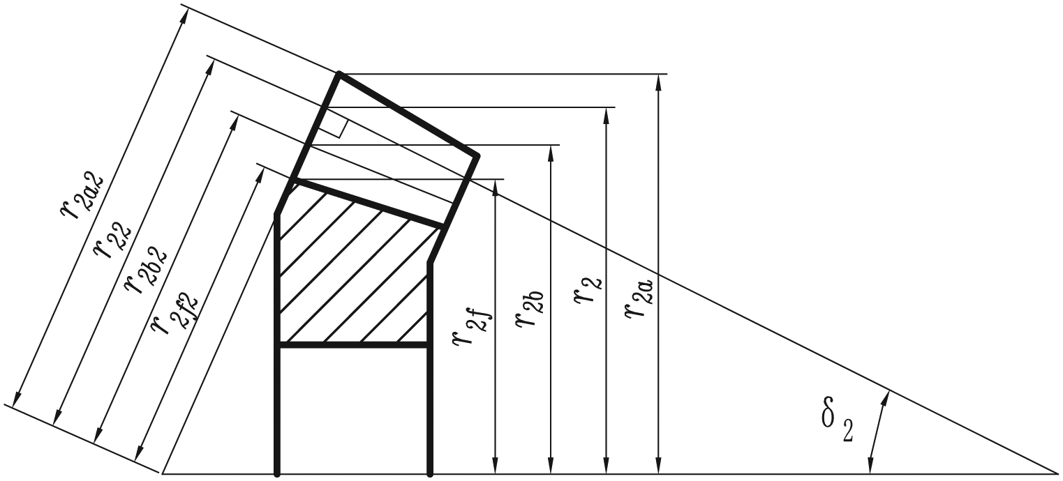
The exterior transverse basic circles of equivalent LSBG include the exterior transverse pitch circle of equivalent LSBG, the exterior transverse addendum circle of equivalent LSBG, the exterior transverse base circle of equivalent LSBG and the exterior transverse dedendum circle of equivalent LSBG. The numerical calculation equations are shown in equation (4)
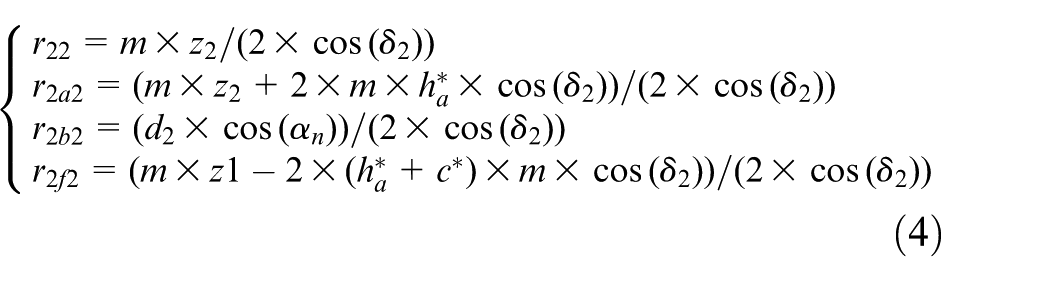
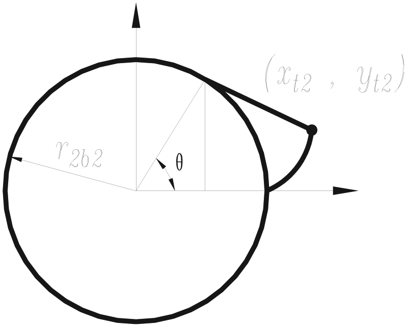
where r22 is the radius of the exterior transverse pitch circle of equivalent LSBG, r2a2 is the radius of the exterior transverse addendum circle of equivalent LSBG, r2b2 is the radius of the exterior transverse base circle of equivalent LSBG and r2f2 is the radius of the exterior transverse dedendum circle of equivalent LSBG. The symbols are shown in Figure 2.
The creation of the basic circles of the exterior transverse equivalent LSBG can be done according to equation (4) and the parameters in Table 1.
The numerical calculation equations for interior transverse basic circles of equivalent LSBG are similar with the exterior transverse.
The modeling principle based on Boolean addition operation
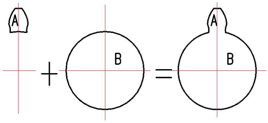
Suppose A and B represent two models, respectively. The Boolean addition operation computation equation between model A and model B can be expressed by the following equation according to the knowledge of computational geometry and computer graphics

where A out B means the part of model A out of model B, and B out A means the part of model B out of model A. The modeling principal chart for LSBG based on Boolean addition operation computation is demonstrated in Figure 3.
The modeling principle of Boolean addition operation.
Creation of the conical logarithmic spiral curve
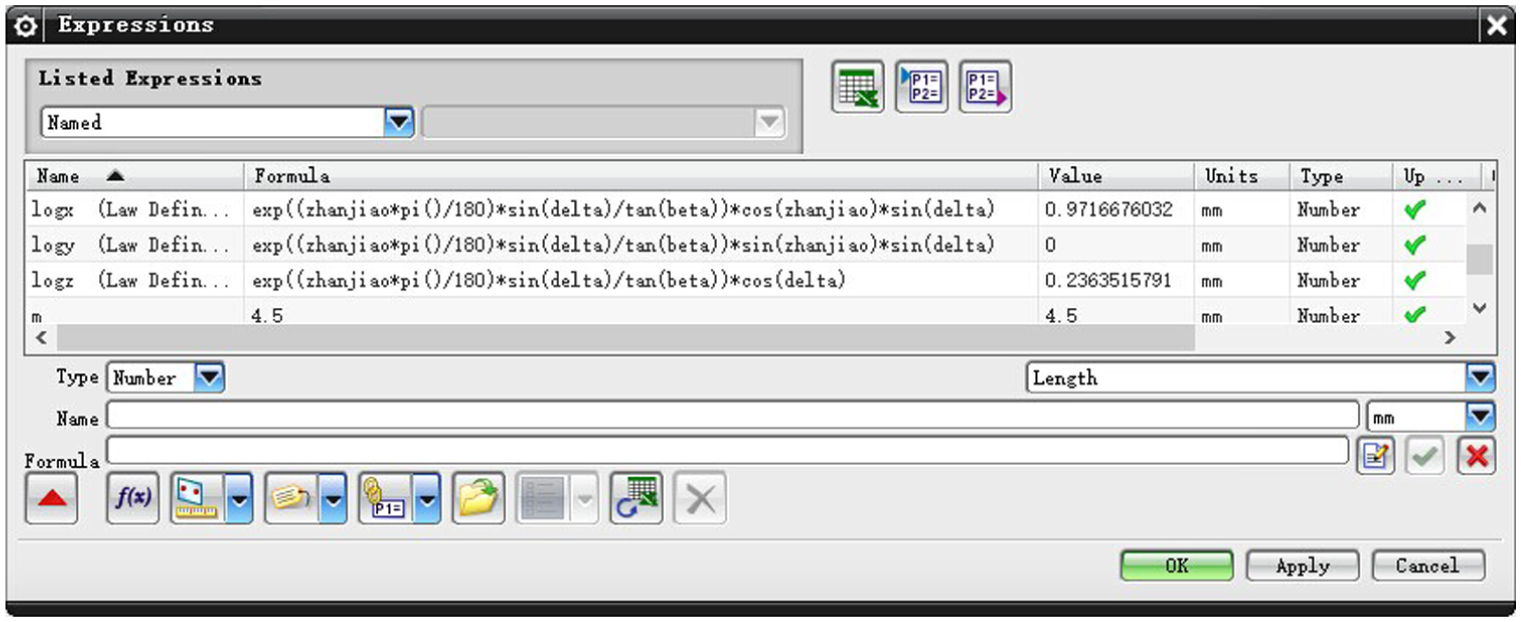
A conical logarithmic spiral curve, expressed in equation (2), can be generated using UG NX software package which offers a curve creation dialog box based on parametric equation as shown in Figure 4.
The creation dialog box of conical logarithmic spiral curve.
The use of the expression function to create a conical logarithmic spiral curve on the pitch cone is shown in Figure 5 by selecting t, logx, logy, and logz for the internal variables, x coordinate, y coordinate and z coordinate, respectively, where t is an internal variable in UG NX software package ranging from 0 to 1. The conical logarithmic spiral curve has the characteristic that the start point r0 = 1, half cone angle α = δ2, spiral angle β = 35° and the bottom surface projection angle φ of M is 190°. The conical logarithmic spiral curve on the pitch cone is the tooth trace curve, and it is also the sweep trace curve for the gear tooth accurate modeling of LSBG.
The logarithmic spiral curve on the pitch cone.
The descriptions and visual expressions of the exterior transverse and interior transverse involutes
The exterior transverse and interior transverse tooth profiles of LSBG are both involutes. The involute equations of exterior transverse can be written in the form of
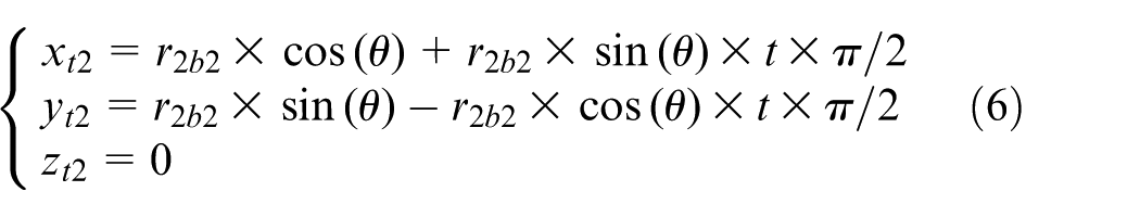
where xt2 is the exterior transverse involutes’x coordinate of LSBG, yt2 is the exterior transverse involutes’y coordinate of LSBG, zt2 is the exterior transverse involutes’z coordinate of LSBG, r2b2 is the exterior transverse equivalent base circle radius of LSBG, θ is the involutes’ spread angle and t is an internal variable in UG NX software package ranging from 0 to 1. The symbols are shown in Figure 6.
The exterior transverse involutes.
One side involutes curve of LSBG exterior transverse was constructed by making use of the curve function of UG NX software package, and the other side involutes curve as shown in Figure 7 was generated by mirroring the constructed involutes curve along the symmetry center axis. The transition curve between the involutes curve and the dedendum circle consists of two segments. The first segment is a transition straight line which starts from the start point (intersection point of involutes and base circle) and is tangent to the involutes curve. The second section is a transition circular arc which connects the first section transition straight line and the dedendum circle. The radius of the transition circular arc rt is defined by the following equation
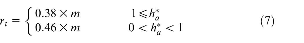
The symbol rt is shown in Figure 7.
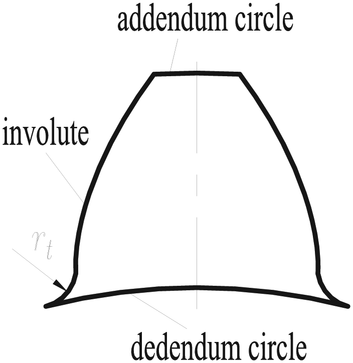
The equivalent gear involutes tooth of exterior transverse.
The interior transverse involutes curve construction of LSBG is similar to the exterior transverse LSBG.
The solid line shown in Figure 8 is the tooth trace curve (swept path) for the gear tooth modeling of the LSBG. The tooth trace curve was generated by selecting the inner surface and the outer surface of the pitch cone for truncating the conical logarithmic spiral curve in Figure 8.
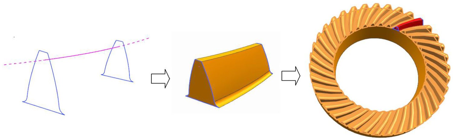
The modeling flow of LSBG.
The sweeping operation of the model can be done by making use of the sweep function of UG NX software package. The user may select the involutes gear tooth profiles from both sides, as shown in Figure 8, as the sweeping section, and choose the tooth trace curve (conical logarithmic spiral curve) with the right curve direction35,36 as the sweeping path. A resulting model of one gear tooth is shown in Figure 8.
The construction of the completed model of LSBG
One tooth in model is created as shown in Figure 8. Now we produce the entire gear wheel by performing an “array” operation. The first tooth is chosen as the source for the operation, the number for array is set to Z2 − 1 and the array center line is set to the root cone axis. The result is shown in Figure 8. Next, the root cone model can be established according to the root cone parameters. Finally, a Boolean addition operation can be performed between the root cone and all gear teeth. The final 3D model of LSBG is generated by a Boolean addition operation between the root cone and all gear teeth.
The machining of the prototype
The prototype processing on five-axis computer numerical control milling machine tool
A medium carbon steel 45 was used to produce the prototype on a DMU 40 MonoBLOCK five-axis computer numerical control (CNC) milling using ball end milling37–40 as shown in Figure 9.
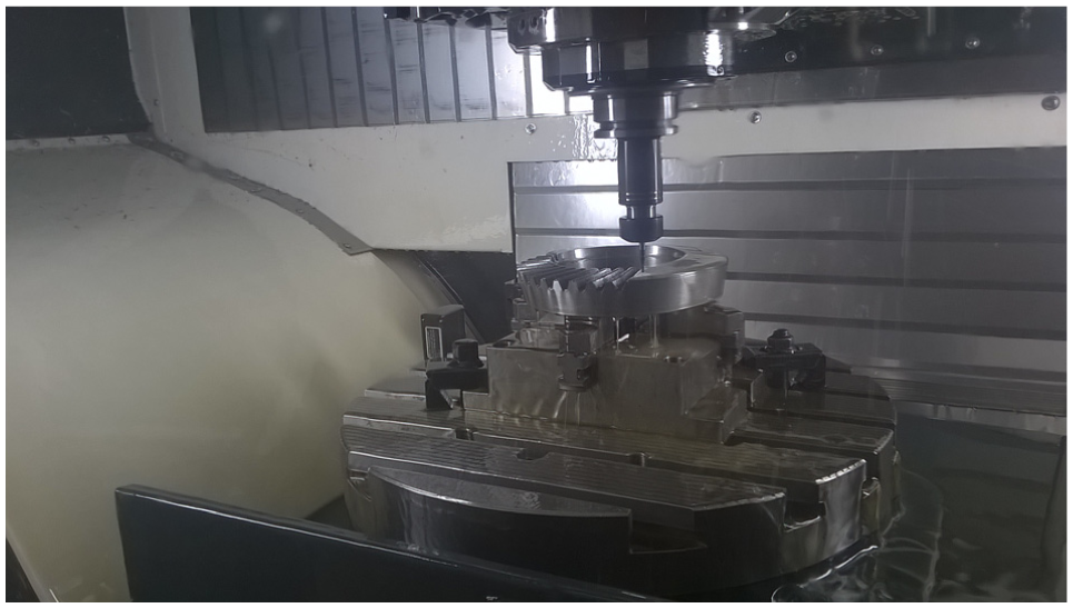
Processing the LSBG on a DMU 40 monoBLOCK five-axis CNC milling machine tool.
The NC programs were generated automatically using the software package of UG CAD system.41–43 UG CAD system has the capability of automatic generation of NC codes for manufacturing of parts as long as a model is input.
The derivations of circle center coordinates and diameter of exterior transverse addendum circle
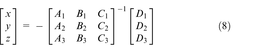
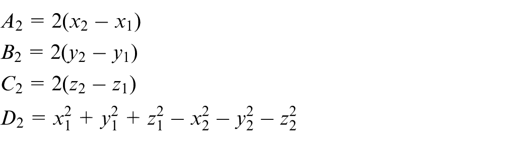
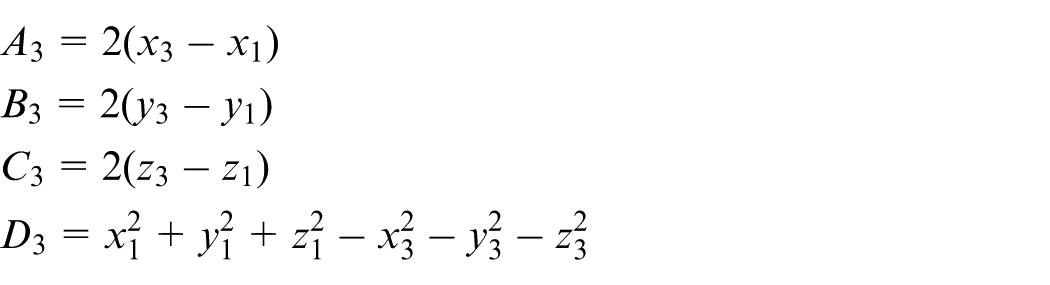
When the coordinates of three points R(x1, y1, z1), S(x2, y2, z2) and T(x3, y3, z3) in space are measured on exterior transverse addendum circle of the LSBG, then the center point O1(x, y, z) and the diameter of the LSBG can be calculated using the following equation
where
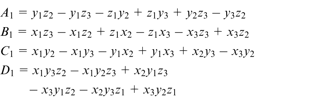
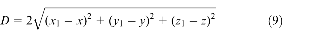
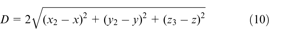
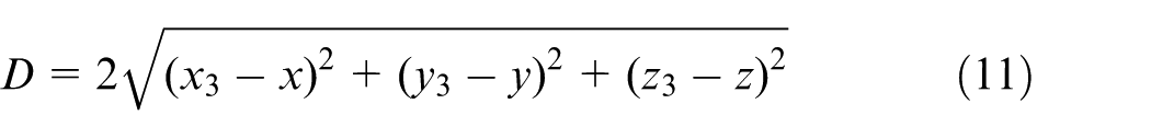
The diameter D is determined by the three points in the form of following expression
or
or
Measuring the exterior transverse addendum circle diameter of LSBG prototype by 3D coordinate measuring instrument
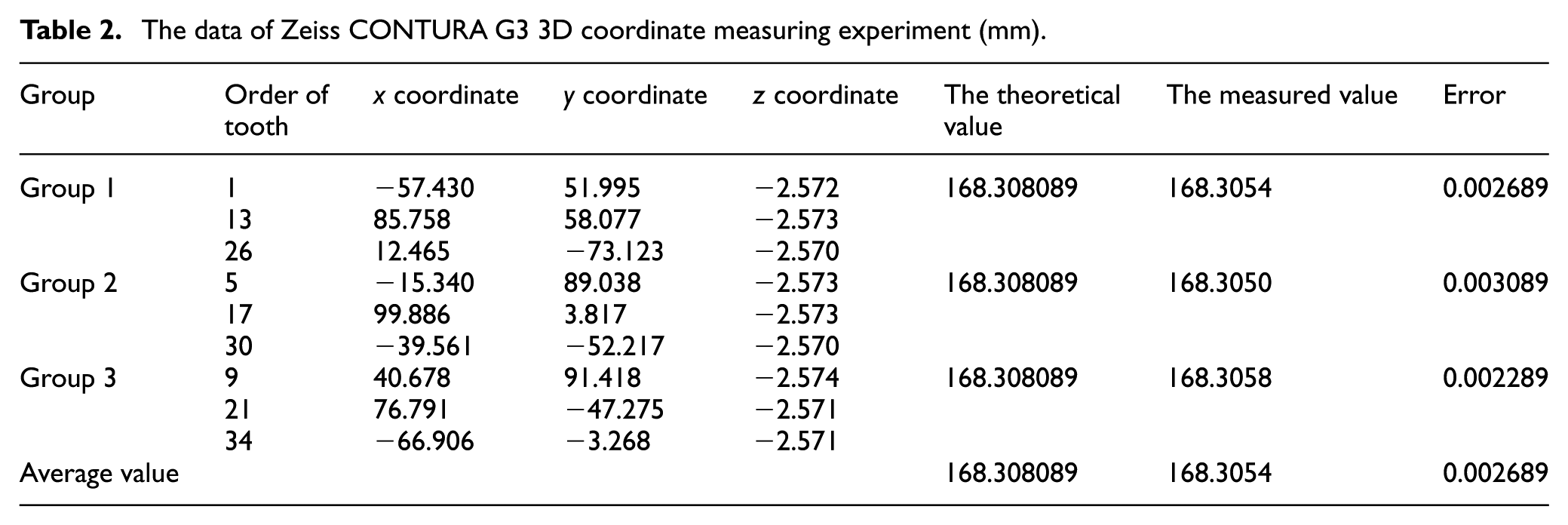
The coordinates of three teeth on LSBG exterior transverse addendum circle were measured using a Zeiss CONTURA G3 3D coordinate measuring instrument. The measured coordinate values are shown in Table 2.
The data of Zeiss CONTURA G3 3D coordinate measuring experiment (mm).
The axial linear error in an axis of DMU 40 monoBLOCK five-axis CNC milling machine tool was measured and got with the value of 0.001 mm. The axial linear error in an axis of Zeiss CONTURA G3 3D coordinate measuring instrument was measured and with the value of 0.0018 mm. The axial truncation error and rounded error of numerical calculation using UG NX software package for modeling are 0.0001 mm. So, the cumulative linear errors in an axis are the sum of those three components

The total linear error in space can be calculated as follows

The x, y, z coordinates of exterior transverse addendum circle of LSBG prototype were measured on Zeiss CONTURA G3 3D coordinate measuring instrument. The exterior transverse addendum circle diameter of each group was calculated according to equations (8) and (9) with the measured data, and the average value of exterior transverse addendum circle diameter of 3 groups was calculated. The measured average value of the exterior transverse addendum circle diameter of LSBG prototype was 168.3054 mm as shown in Table 2.
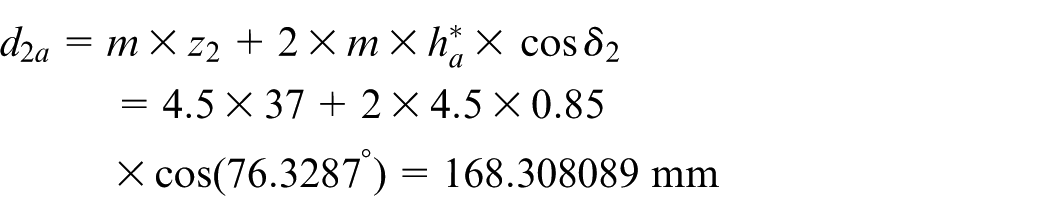
The calculated theoretical values of exterior transverse addendum circle diameter of LSBG can be written as follows according to equation (3)
The average error for exterior transverse addendum circle diameter of the LSBG prototype between theoretical calculations and measured data is

It is about 0.0027 mm after date are rounded.
Discussion and conclusion
The method based on Boolean addition operation between the tooth models and the root cone of LSBG is used for LSBG accurate modeling, whose number of teeth was 37, with modules being 4.5 mm, normal pressure angle being 20° and spiral angle being 35°. The theoretical error of this modeling method is zero, and the actual model had a linear error less than 0.1 µm.
The prototype of LSBG was successfully processed on a DMU 40 monoBLOCK five-axis CNC milling machine, and the material of the LSBG was medium carbon steel 45.
The Zeiss CONTURA G3 3D coordinate measuring instrument was used to measure x, y, z coordinate values of three points on exterior transverse addendum circle of the LSBG prototype with three groups. According to the space geometry, the average diameter of the exterior transverse addendum circle can be calculated by the x, y, z coordinate values of three points. The greatest linear error between the theoretical value and the measured average value is 0.0027 mm.
An accurate model of LSBG was created based on the gear tooth flank formation mechanism and the Boolean addition operation. The fabrication of the LSBG prototype was completely carried out on the above model with rather high precision. Both may pave the way for LSBG design and manufacture for the applications in industry.
The parametric modeling of the LSBG as well as the machining efficiency for the product is still in expertise of the future work.
Footnotes
Appendix 1
Declaration of Conflicting Interests
The author(s) declared no potential conflicts of interest with respect to the research, authorship, and/or publication of this article.
Funding
The author(s) disclosed receipt of the following financial support for the research, authorship, and/or publication of this article: This work was sponsored by the National Natural Science Foundation of China named “Research on standing wave mechanism and experiment for the failure of high-speed tire blow-out” under grant no. 51475399 and the Science and Technology Projects named “Research on meshing dynamics of logarithmic spiral bevel gear” under grant no. JA14239 of Education Department of Fujian Province, China.