
Abstract
To realize the efficient and precision truing of arc-shaped diamond wheel, a novel on-machine precision form truing of arc-shaped diamond wheel is proposed utilizing rotary green silicon carbon rod, and online monitoring of the truing process by acoustic emission was studied. Through this truing method, any required radius of wheel arc profile could be formed by programmed truing paths; meanwhile, the vertical direction position error of the wheel center could be corrected after truing. In order to improve the truing efficiency, the acoustic emission signal was processed to monitor the truing process, and the AErms threshold of judging the finishing truing time was obtained.
Introduction
The development of advanced optoelectronic and astronomical devices highly demands for optical components and molds with spherical, aspherical and free-form surfaces with high profile accuracy and excellent surface finish.1–4 Most of these components and molds have to be machined by abrasive processes with diamond wheels due to their hard-brittle materials property, such as ceramics, cements, optical glasses and crystalline materials.5–7
The arc-shaped diamond wheels with precision profile were usually adopted for ultra-precision grinding of spherical, aspheric and free-form surfaces.8,9 The form accuracy of the ground surface was mainly determined by the profile accuracy of wheels.10,11 To improve the accuracy of the arc-shaped diamond wheel in truing process, cup truer with a cyclical arc swing mechanism, form crush dressing method, wire electro discharge method (Wire-EDM) and the fixed green silicon carbon (GC) stick computer numerical control (CNC) mutual-wear truing were developed to true arc-shaped wheels.12–15 Nevertheless, most of the above truing methods need complicated attached devices.
Besides, the production efficiency can be improved and the wastage of wheel abrasive layer can be decreased with accurate judgment of the finishing truing time. 16 The acoustic emission (AE) technology is well used to monitor truing process of flat wheel; 17 however, online monitoring of truing arc-shaped diamond wheel has been little investigated. 18
Based on the above, a novel precision truing method of arc-shaped diamond wheel was proposed utilizing mutual-wear between diamond wheel and GC rod without any complex accessory first. And then, the online monitoring system of truing process with rotary AE sensor was established. Finally, the AE signal in truing process was studied to monitor the truing performance.
Truing and monitoring technical solution
Truing principle of arc-shaped diamond wheel
Figure 1 shows the truing mechanism. In the truing process, the GC grains rub and remove the bond of diamond wheel and then the holding ability of the bond for some diamond grains is decreased so that the diamond grains like ①, ② and ③ fall off, and the diamond grains like ④, ⑤ and ⑥ are protruded out of the wheel bond. Meantime, the similar removal mechanism emerges on the GC rod, the GC grain like ⓐ falls off and the grains like ⓑ and ⓒ are protruded out of the GC rod bond. The only difference is the GC grains may be broken like ⓑ and ⓒ because of mutual strike with the diamond grains.
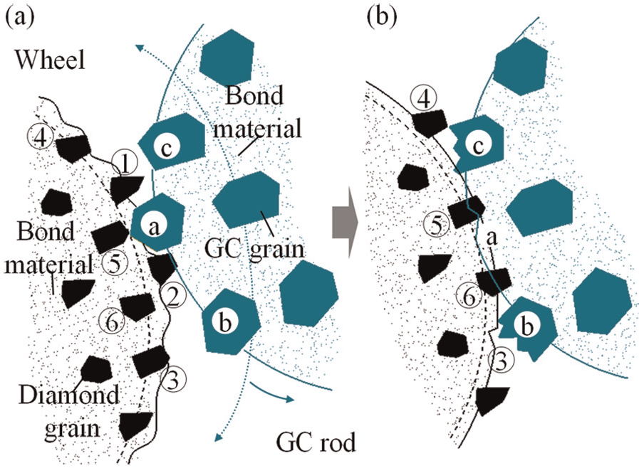
Truing mechanism: (a) initial truing and (b) truing process.
Figure 2 shows the truing principle of arc-shaped diamond wheel. In truing process, the GC rod is driven by the workpiece spindle on the machine with the wheel speed n to true diamond wheel with the wheel speed N along the circular interpolation paths circularly with the feed rate v in CNC grinding system as shown in Figure 2(a), then a arc-shaped wheel may be gradually formed with the depth of cut ap through the CNC mutual-wear between the diamond wheel and GC rod dresser. Besides, the motion paths were designed to utilize more cylinder of GC rod to true the arc profile of diamond wheel as shown in Figure 2(b). In the motion paths, when a circular interpolation path is completed, the diamond wheel is moved with the distance B along negative direction of Z-axis, then the next circular interpolation movement is carried out, and the cycle is kept going until the terminal of motion paths. After finishing the positive motion paths, the inverse movements are executed back to the beginning of motion paths. In short, the arc-shaped diamond wheel can be trued by rotary GC rod with circular interpolation paths and motion paths.
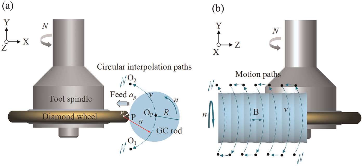
Truing mode of arc-shaped diamond wheel: (a) truing mode and (b) truing motion paths.
The radius of interpolation arc a is described as Exp. (1). Any radius of wheel arc profile can be obtained for different requirements by changing the radius of interpolation arc

where R is the radius of GC rod which can be measured in truing process, and r is the expected radius of wheel arc profile, as shown in Figure 2(a).
In the truing process, however, the radius of GC rod is decreased unavoidably because of the mutual-wear. According to Exp. (1), the actual radius of wheel arc profile would be increased and deviate from the expected radius largely in truing process if the radius of interpolation arc remain the same. Therefore, the radius of interpolation arc needs to be compensated by the radius of GC rod measured in truing process to guarantee the radius of arc profile wheel to meet the expected radius as follows

where
Considering the symmetry of the circular interpolation paths in XOY plane, the center position YP of wheel arc profile in vertical direction can be confirmed as follows
where Y1, Y2 is vertical direction coordinate of the interpolation arc beginning O1 and terminal O2, as shown in Figure 2(a), then tool setting position of diamond wheel in the vertical direction is confirmed.
AE monitoring technical solution
Figure 3 shows the flowchart of AE signal transmission. The rotor AE sensor was installed on the bolt which is used to fix the wheel, and the stator AE sensor was installed on the displacement vernier device in vertical direction, which can keep the space below 1 mm between the end faces of two sensors. Besides, when truing, the AE signal is transmitted from ① to ② through abrasive layer and metallized substrate of wheel and arrived at rotor AE sensor ③ through the grinding spindle and the bolt and then the AE signal is transmitted from the sending end of rotor sensor to the receiving end of stator sensor through air by wireless transmission; hereafter, it is transmitted to the computer through controller and data acquisition card by cable transmissions.
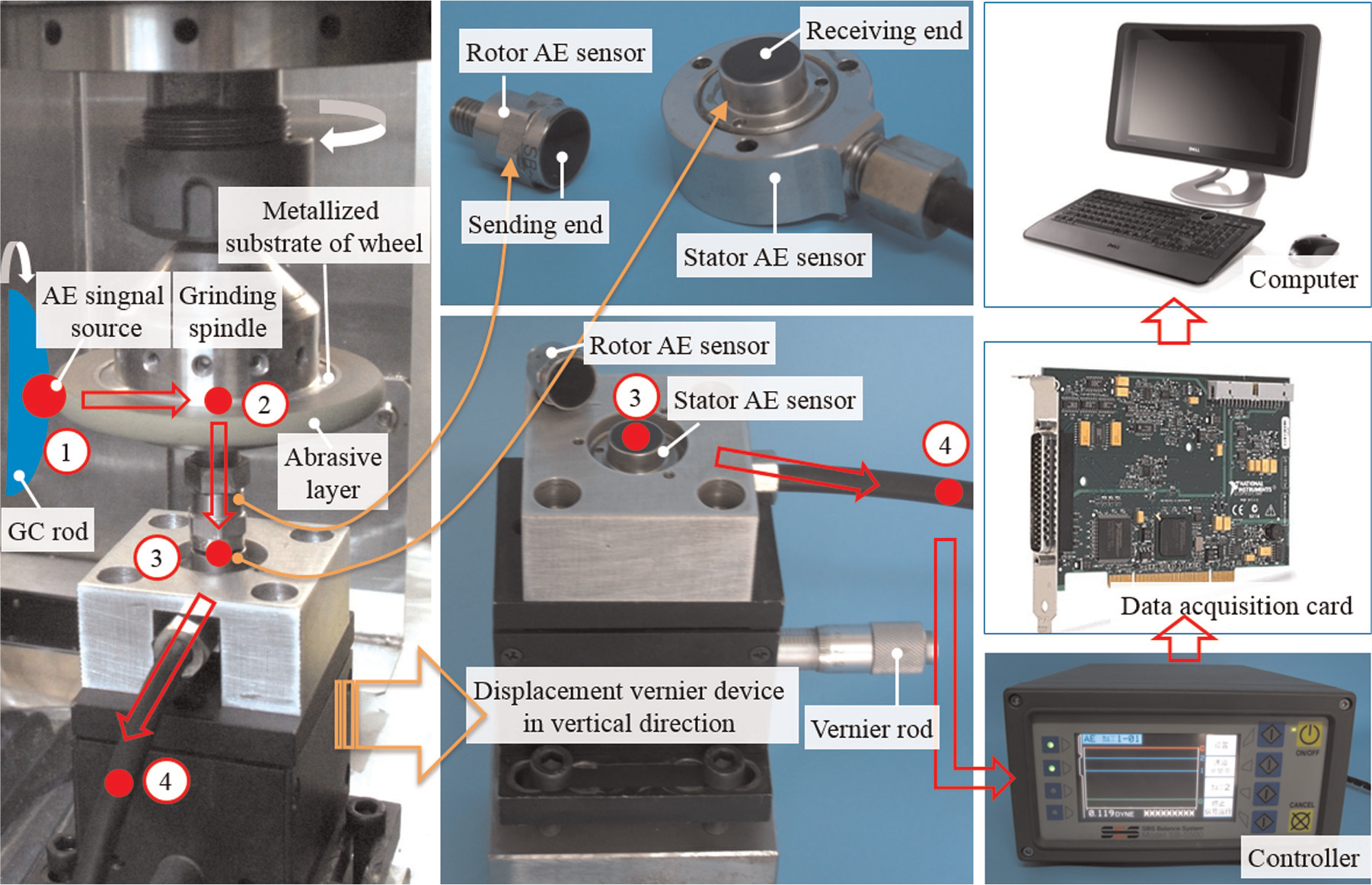
The flowchart of AE signal transmission.
Truing and monitoring experimental setup
Figure 4 shows the on-machine truing and online monitoring experimental setup. The AE signal was collected by data capture system based on grinder (see Figure 4(b)). The details of truing conditions and truing parameters are shown in Table 1. The profile of arc-shaped wheel was measured by laser scan micrometer (LSM); the morphology of wheel surface was examined by a large scene depth laser microscope (LSDLM) and a scanning electron microscope (SEM).
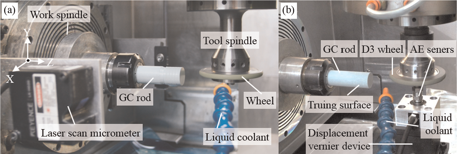
(a) On-machine truing and (b) online monitoring experimental setup.
Truing and monitoring conditions.
GC: green silicon carbon; AE: acoustic emission.
Truing performance and online monitoring
Truing performance
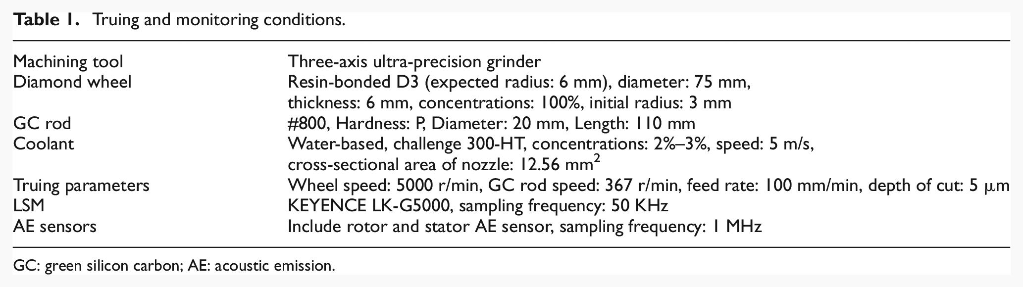
Figure 5 shows the truing performance. As shown in Figure 5(a), before truing, many measured points were far away from and zigzagged around the fitting arc profile, while the measured points agreed well with the fitting profile arc after truing, and the wheel condition was improved significantly as shown in Figure 5(b). The trued radius of wheel arc profile is 5.765 mm, which is close to the expected radius of 6 mm; it means any required radius of wheel arc profile could be formed. The form deviations of the wheel profile before and after truing were obtained by removing their power values as shown in Figure 5(c) and (d), and it could be observed intuitively that the form deviation and the run-out error was reduced significantly from 32 to 2.3 µm after truing, which was conducive to obtain precision surface in subsequent grinding process. Because of the optical collection principle, the irregular surface of diamond grains on the wheel profile surface may reflect the laser disorderly and generate noises inevitably in the LSM measuring process. Therefore, the form deviation in the range of 99% probability of the measured points was considered as actual form error in this article. As shown in Figure 5(e) and (f), the wheel arc profile form error of 2.5 µm after truing decreased about 93% contrast of 35 µm before truing.
Truing performance of D3 wheel: (a) wheel profile before truing, (b) wheel profile after truing, (c) form deviation before truing, (d) form deviation after truing, (e) probability distributions of form deviation before truing and (f) probability distributions of form deviation after truing.
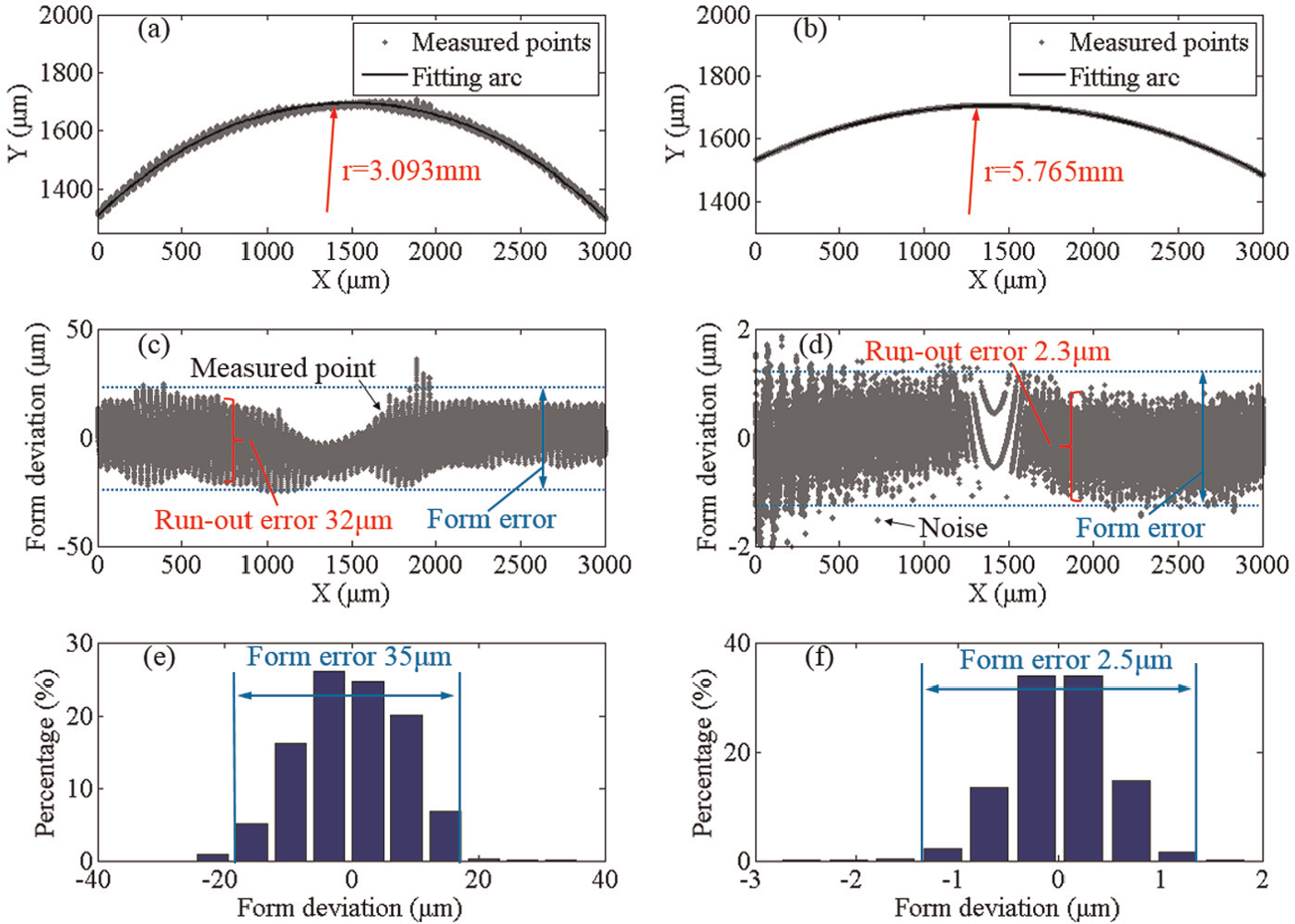
Figure 6 shows the SEM and LSDLM photographs of wheel surface. The wheels were well trued as shown in Figure 6(a). As shown in Figure 6(b), the diamond grains were well distributed on the wheel surface, protruded out of the wheel bond and their cutting edges were also sharpened. This means that the truing method is not only valid to create high accuracy form of diamond wheels but also could protrude the abrasive grains out of the wheel bond. Before truing, the arc profile topography transited wavily and existed a lot of raised and foveate stripe on the wheel surface, as shown in Figure 6(c), which certainly reduced the form accuracy of the wheel profile. After truing, the formed arc profile topography was uniform and smooth as shown in Figure 6(d). Therefore, the wheel performance was improved obviously in macroscopic view.
SEM and LSDLM photographs of wheel: (a) D3 resin-bonded wheel, (b) SEM photograph after truing, (c) LSDLM before truing and (d) LSDLM after truing.
Online monitoring of truing process
Figure 7 shows the AE original signal of truing process. As shown in Figure 7(a), the AE signal was intermittent at the early stage of truing process in once interpolation. It seems to be caused by the discontinuous wheel arc profile; the AE truing signal was generated by crashing between the convex arc profile and GC rod, while no truing AE signal was generated because of no friction between concave arc profile and GC rod. Meantime, the discontinuous AE signal with cycle of 12 ms was found at early stage (see Figure 7(c)). It seems to be caused by wheel run-out error; the cycle of 12 ms was every turn time of wheel (5000 r/min). Compared with AE signal at the early stage of truing process, it has smooth transition without cycle of 12 ms and was lower at end stage of truing process. It seems to be caused that wheel arc profile form error and run-out error were decreased and eliminated because of truing, and the signal intensity was lower in continuous truing at the end stage than in intermittent and impactive truing at the early stage. Besides, it was first increased and then decreased. Because of the wheel arc profile construction and wear of GC rod, the actual depth of cut is first increased and then decreased, which caused the change in AE signal.
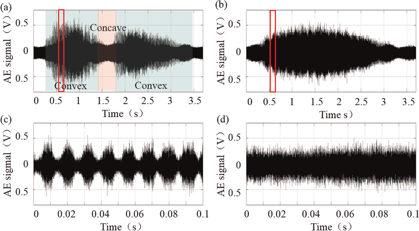
AE original signal of truing process: (a) AE signal at the early stage in once interpolation, (b) AE signal at the end stage in once interpolation, (c) intercepting 100 ms AE signal at the early stage and (d) intercepting 100 ms AE signal at the end stage.
Above all, when the wheel arc profile form error and rotation error were eliminated, the truing process needs to be ended. In other words, the truing process needs to be ended when the AE signal has smooth transition without cycle of 12 ms in once interpolation. However, the AE original signal is periodic signal with positive and negative variations; it is difficult to judge the end time of truing process with its amplitude. Therefore, the root mean square (RMS) of AE signal was processed to obtain positive signal, which is described as 19
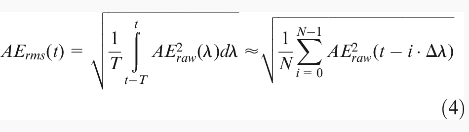
where AEraw is the AE original signal, T is the integration constant time, N is the quality of AE original signal data points and Δλ is the time of obtaining one AE original signal data point.
According to the viewpoint of J. Webster, the integration time constant is chosen from 0.01 to 20 ms; in this article, 0.2 ms is chosen as the integration time constant, and in other words, a AErms data point was calculated by 200 AE original signal data points.
Figure 8 shows the AErms in truing process. After processing the AE original signal, the effect of wheel errors on AErms signal still could be observed at the early stage as shown in Figure 8(a) and (c), such as, AErms with cycle of 12 ms, intermittent AErms. AErms also has smooth transition without cycle of 12 ms, was lower at end stage of truing process, was first increased and then decreased as shown in Figure 8(b) and (d). Besides, AErms with cycle of 163.5 ms was found both at early and end stages as shown in Figure 8(c) and (d), it seems to be caused by GC rod speed (367 r/min), the GC rod rubbed the wheel and liquid coolant. However, compared with AErms at the early stage of truing process, it could be observed that AErms was above 0.005 V with continuous 2.5 s, which was slightly less than the time of once interpolation (about 2.75 s) at the end stage. Therefore, if AErms is above 0.005 V within continuous time, which was slightly less than the time of once interpolation, the truing process needs to be ended.
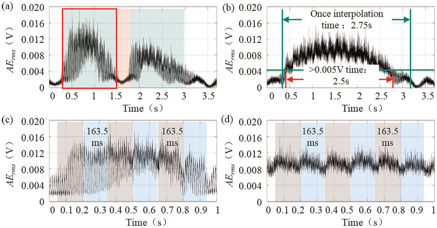
AErms of truing process: (a) AErms at the early stage in once interpolation, (b) AErms at the end stage in once interpolation, (c) intercepting 1 s AErms at the early stage and (d) intercepting 1 s AErms at the end stage.
Conclusion
The on-machine truing method is able to realize the precision truing of resin-bonded arc-shaped diamond wheels with any designed radius, and tool setting position error of the wheel in the vertical direction can be corrected after truing.
After truing, the trued radius of wheel arc profile is 5.765 mm, which is close to the expected radius of 6 mm, the run-out error was reduced significantly from 32 µm before truing to 2.3 µm and the form error of 2.5 µm after truing decreased about 93% in contrast to 35 µm before truing.
The AE signal was processed to monitor the truing process, and the threshold of judging the finishing truing time was obtained to improve the truing efficiency.
Footnotes
Acknowledgements
The authors gratefully acknowledge the financial support of National Natural Science Foundation of China.
Declaration of conflicting interests
The author(s) declared no potential conflicts of interest with respect to the research, authorship, and/or publication of this article.
Funding
The author(s) disclosed receipt of the following financial support for the research, authorship, and/or publication of this article: This work was supported by National Natural Science Foundation of China (Grant Nos 51405108 and 51475109).