
Abstract
The aim and objectives of this article are to provide an analytical model for the incremental forming of gears along the direction perpendicular to the sheet thickness. The model allows determining the influence of the major process parameters in the indentation force and in the material volume undergoing plastic deformation during indentation by means of double-wedge gear tooth punches. Special emphasis is placed on the influence of superimposing tension stresses along the in-plane direction. The analytical model is built upon the slip-line theory under plane strain deformation conditions, and results are compared against those obtained from experiments in DC04 mild steel and from numerical simulations performed with the finite element method. Results show that the indentation force can be significantly reduced by stress superposition, and that a minimum distance from previous indentations is necessary to produce a new gear tooth in a material free from residual strains and stresses.
Keywords
Introduction
A recent keynote publication by Merklein et al. 1 identified sheet–bulk metal forming (SBMF) as a new technology in which conventional SBMF processes are combined to plastically deform sheets and plates with intended three-dimensional material flow. The objective of SBMF is the production of net-shape (or near-net shape) sheet metal components with local functional features such as teeth, ribs and solid bosses positioned within or outside the plane of the sheets or plates from which they are produced. The integration of these functional features in the original blanks and the consequent reduction in parts to be assembled not only enhances the overall robustness and reliability of the components but also shortens process chains and reduces manufacturing costs.
Two earlier publications by Merklein et al.2,3 may be considered as the pioneering works in the field, despite previous applications of special-purpose sheet–bulk processes to the production of specific industrial parts. The first publication discusses the production of SBMF components by deep drawing with integration of external, shaped carrier elements and the forming of high-precision gearings in sheets by extrusion. In both cases, the forming load is mainly applied across the sheet thickness. The second publication explores the utilization of three-dimensional finite element analysis to investigate plastic flow in SBMF processes involving upsetting/lateral extrusion and deep drawing/upsetting forming stages.
The aforementioned keynote paper by Merklein et al. 1 includes a comprehensive state-of-the-art review of SBMF technology with special emphasis on tools, tribology and metrology of industrial processes. However, references to fundamental studies on plastic flow and failure are scarce and mainly consisting on the application of commercial finite element computer programs to specific SBMF processes.
In a recent publication, Sieczkarek et al. 4 presented the first investigation aimed at characterizing the deformation mechanics of SBMF processes in which loading is applied along the direction perpendicular to the sheet thickness. The work involved indentation by a flat punch and provided the first closed-form analytical solution to estimate pressures and forces in SBMF processes.
This new line of research that aims providing a new level of understanding on plastic flow in SBMF by combining theory and experimentation will be extended within this article to the incremental forming of gears by indentation along the direction perpendicular to the sheet thickness (Figure 1). The new proposed process is an effective, economic alternative to fine blanking in the case of customized low batch production and eliminates typical problems related to the wear resistance of die materials under extreme shearing loads. 5
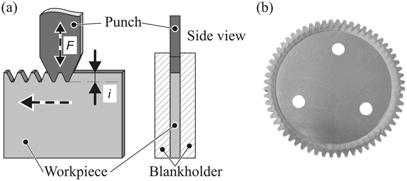
Incremental forming of gears by indentation along the direction perpendicular to the sheet thickness: (a) schematic representation of the process and (b) photograph of a disc with gear teeth produced by sheet–bulk metal forming.
In incremental forming of gears by indentation along the direction perpendicular to the sheet thickness, the gear teeth are produced within the plane of the sheets, and special emphasis is placed on the reduction in the applied pressures and forces by stress superposition. This is particularly important in the case of small punches and dies subjected to high forming forces.
Force reduction by superposition of stresses had been previously accomplished by Becker et al., 6 who showed that application of compression stresses in incremental tube forming can significantly reduce the required bending moment and springback. Therefore, from a technological point of view, one of the main objectives of this article is to apply this concept of stress superposition to the incremental forming of gears by indentation along the direction perpendicular to the sheet thickness.
This objective may also be seen as an alternative to the application of bionic structures on the active surfaces of the punches by micromilling, as it was earlier done by Sieczkarek et al. 7 In fact, customization of the active tool surfaces is not only costly and time-consuming, but also it is limited to force reductions below 20% due to minimum requirements in the overall contact area that influence friction and the compression forces.
The deformation mechanics of the incremental forming of gears by indentation along the direction perpendicular to the sheet thickness is analysed by means of a combined experimental and theoretical investigation. The experimental work is performed in DC04 mild steel, and the theoretical work involves the development of an analytical model based on the slip-line theory and process simulation with finite elements. Of particular and interesting value to the design and fabrication of gears is the ability of the analytical model to determine the stress field and the expected reduction in force by superposition of stresses. The capability to predict the extent of the plastically deformed region and to establish the minimum distance between two successive gear teeth indentations is another key feature of the proposed analytical model.
Experimentation
Material characterization
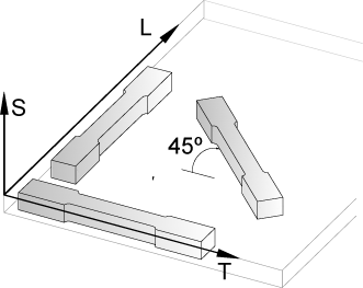
The experiments were performed in DC04 (WN 1.0338) mild steel sheets with 3 mm thickness at room temperature. This material is appropriate for cold forming operations, and its mechanical characterization was carried out on a Zwick Z250 universal testing machine under quasi-static loading conditions using tensile test specimens cut out from the supplied sheets at 0°, 45° and 90° with respect to the rolling direction (RD). The overall experimental procedure followed the ASTM Standard E8/E8M, 8 and the average stress–strain curve was approximated by the following Ludwik–Hollomon’s strain hardening material model

Table 1 presents a summary of the mechanical properties obtained from the tensile tests.
Summary of the mechanical properties of DC04 mild steel sheets with 3 mm thickness.
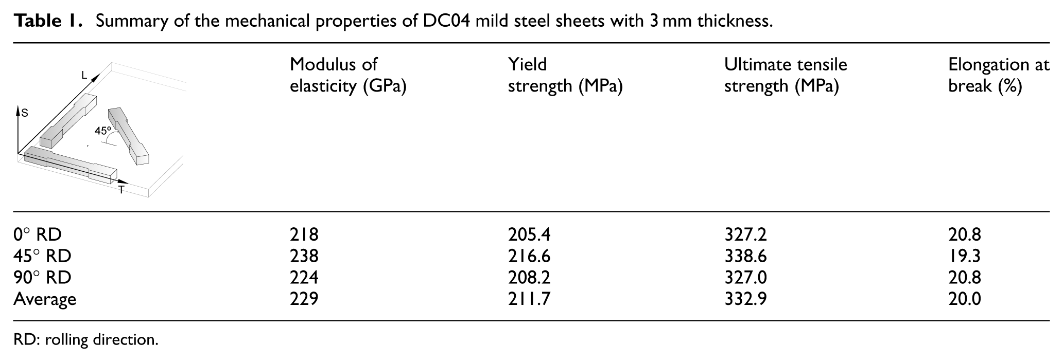
RD: rolling direction.
Experimental methods and procedures
The experiments were carried out on a five-axis forming press that was specially designed by Sieczkarek et al. 9 for incremental SBMF processes. The machine is equipped with four hydraulic linear axes and a turntable rotary axis and is capable of performing different sheet–bulk forming sequences such as embossing, rolling and compression, among others.
The availability of more than one hydraulic linear axis is an important feature of this machine because it enables superposition of stress by means of an independent force
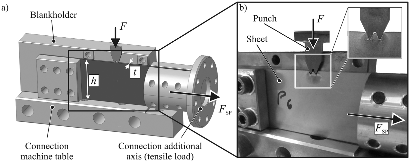
Incremental forming of gears by indentation with superimposed horizontal tensile stresses: (a) schematic representation of the experimental set-up (one side open) and (b) photographic details showing the working area and the region adjacent to the punch.
The punch was manufactured from a powder metallurgy high-speed steel ASP2023 (WN 1.3344) and vacuum hardened in order to ensure a surface hardness of approximately 60 HRC. The blank holders were made from St37S 235 JR G2 (WN 1.0038) steel plates and included screws to clamp the sheets firmly in position during the tests. A clearance of 0.1 mm was left between the sheet and the blank holder in the plastically deforming region in order to avoid contact. This clearance was small enough to limit the amount of flash that was formed between the punch and the blank holder to a minimum. The overall set-up was secured to the machine worktable by additional screws.
The main process parameters are as follows: (1) the double wedge-shaped profile of the gear tooth punch, (2) the indentation depth i, (3) the superimposed stress
In case of the tests performed with stress superposition, the procedure involved operating the machine in two different actions. The first action consists of applying a horizontal force
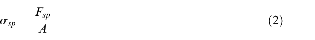
The symbol A denotes the initial cross section of the sheet given by
Analytical model
The analysis of the transient plastic flow associated to the incremental forming of gears by indentation along the direction perpendicular to the sheet thickness was performed by means of an analytical model built upon the slip-line theory. The model proposes various slip-line fields for the different stages of the process (Figure 3) and is based on previous work by Prandtl 10 and Hill 11 on the indentation and compression of a medium with a flat punch.
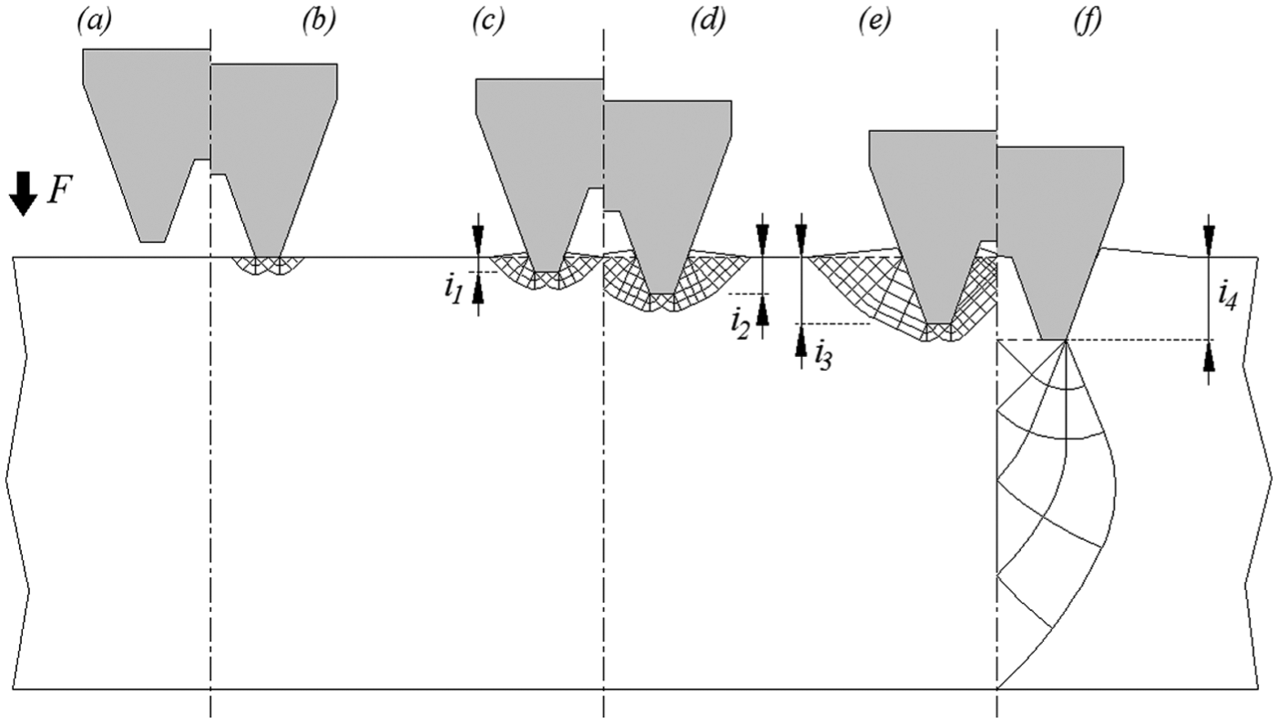
Slip-line field solutions for the incremental forming of gears by indentation along the direction perpendicular to the sheet thickness: (a) no contact between the punch and sheet, (b) beginning of the process, (c) instant of time when plastic deformation meet in one point of the punch centre line, (d) solution for the instants of time when plastic deformation meet along the punch centre line, (e) solution for the final instants of time to completely form the gear tooth and (f) solution for an instant of time corresponding to a punch displacement beyond what is needed to form the gear tooth.
Figure 3(b) shows the proposed incipient slip-line field at the beginning of the process which is derived from that developed by Prandtl 10 in the 1920s for the indentation of a semi-infinite medium with a flat punch. Figure 3(c)–(e) shows different types of unsteady slip-line fields that are valid for different instants of time corresponding to various indentation depths i of the gear tooth punch.
Figure 3(c), for example, suggests a slip-line field for the indentation depth
The analytical model to be presented in this article is focused on the slip-line field, as shown in Figure 3(e), because it allows analysing plastic flow at the instant of time when the gear tooth is completely formed. The indentation force F with and without stress superposition is derived from the distribution of stress within the plastic deformation region that is computed from this slip-line field under the following assumptions: (1) the plastic flow across thickness is negligible, (2) the material is isotropic, homogeneous and rigid-ideally plastic (i.e. no strain hardening effects are taken into account), (3) the effects of temperature and strain rate are ignored and (4) friction, when present, is modelled by means of a coefficient of friction
As a result of the above-mentioned assumptions, the proposed analytical model considers plastic deformation to take place under plane strain deformation conditions and leaves material strain hardening out of the process parameters. Figure 4(a) presents details of the slip-line field, shown in Figure 3(e), and of the main angular relationships that are needed to determine the stress distribution within the plastic deformation region (Figure 4(b)).
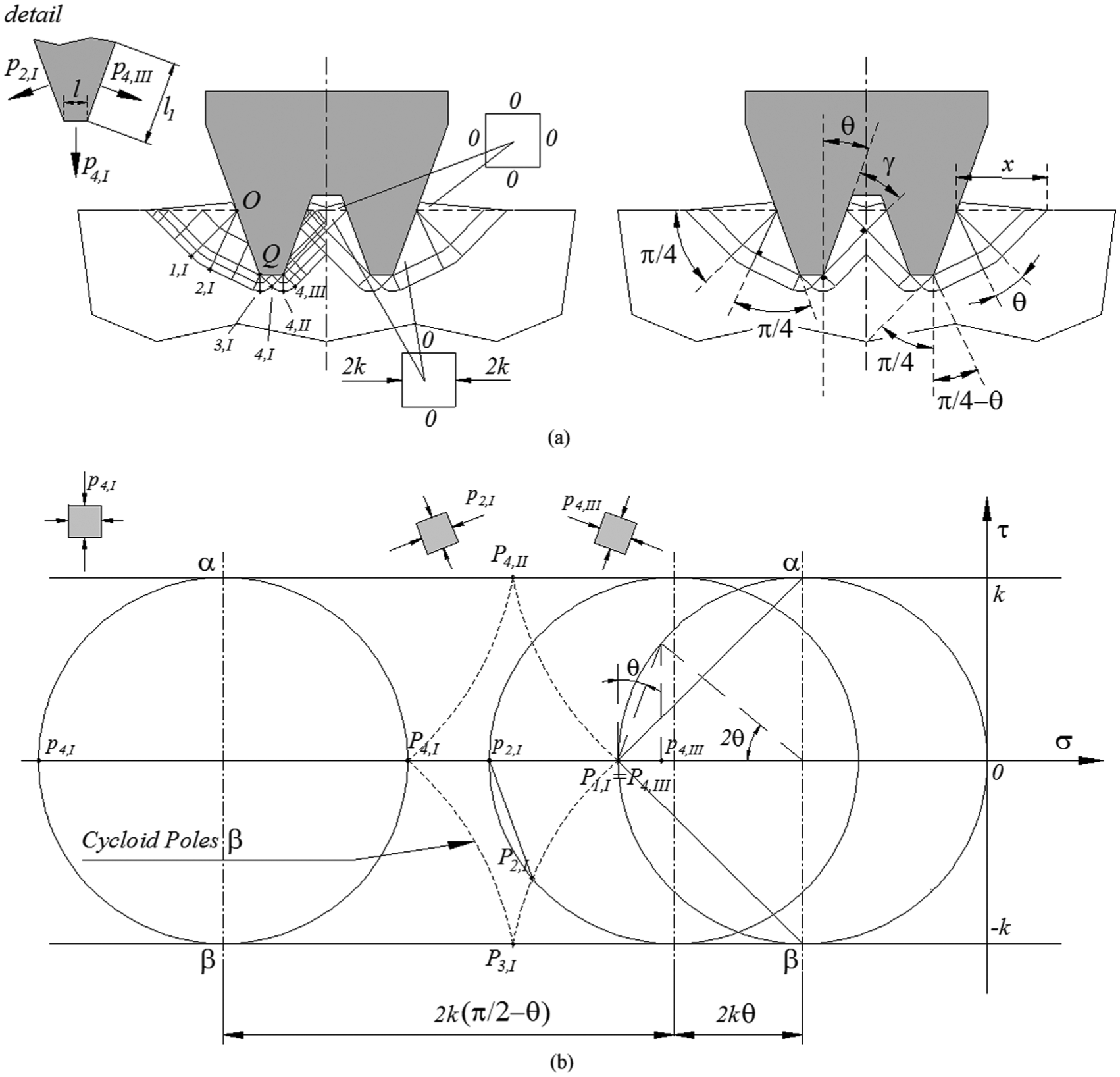
Incremental forming of gears by indentation along the direction perpendicular to the sheet thickness: (a) slip-line field for the final instants of time to form the gear tooth and (b) Mohr circles in the stress plane for the slip-line field shown in (a).
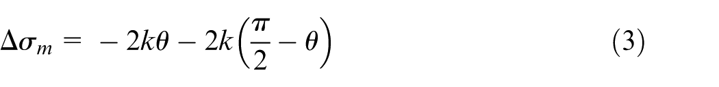
The slip-line field in Figure 4(a) makes use of three different pairs of centred fans with included angles equal to
The dashed lines limiting the straight lines of constant average stress in the uppermost regions of the slip-line field represent a discontinuity in stress between the rigid material and the plastically deforming regions. While observing the volume elements included in these regions (refer to Figure 4(a)), it is worth noting that
As a result of this, the stress field in point
The corresponding poles of the Mohr circles are plotted as
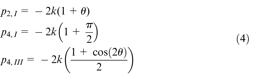
The normal pressure

where
In case of stress superposition, the sheet is subject to a horizontal tensile force
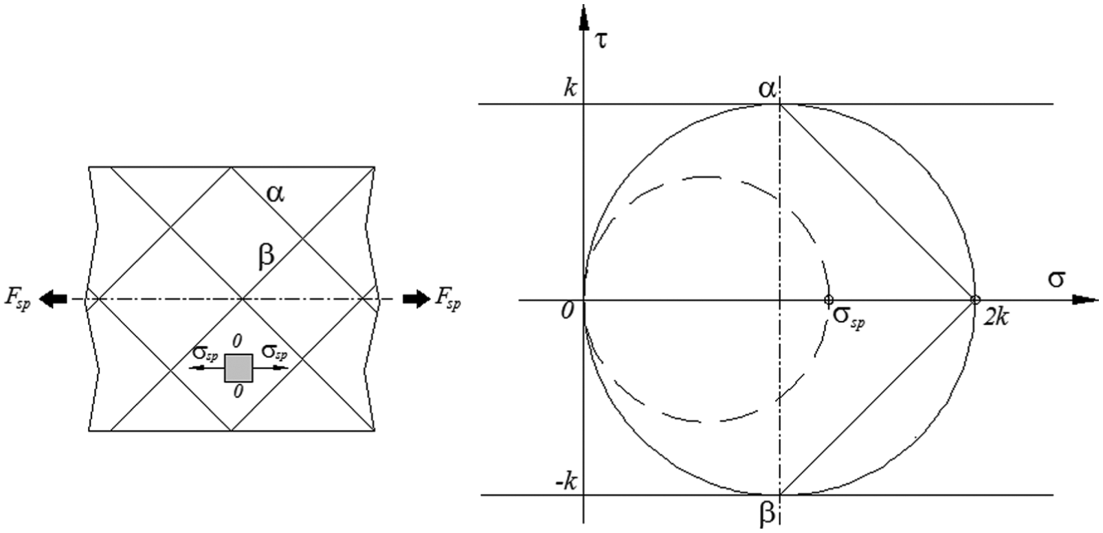
Slip-line field and corresponding Mohr circle in the stress plane for the pre-stress tension stage that is applied before starting the incremental forming of gears by indentation along the direction perpendicular to the sheet thickness.
As shown in Figure 5, the force
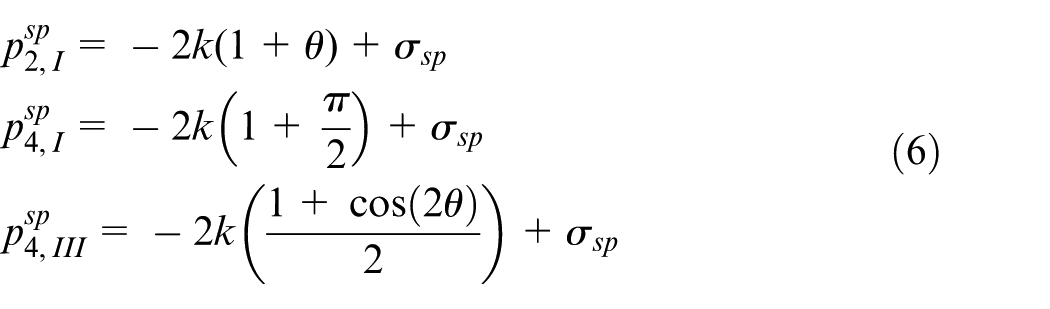
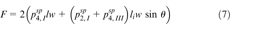
As a result of this, the vertical indentation force F to form the gear tooth with stress superposition
The following section compares the indentation forces F (with and without stress superposition) calculated by the means of the proposed analytical model with finite element estimates and experimental results obtained in DC04 mild steel sheets with 3 mm thickness. The slip-line field solutions of the intermediate stages of deformation shown in Figure 3(b)–(d) will also be used to obtain intermediate estimates of the indentation forces.
Results and discussion
Assessment of the proposed slip-line fields
Figure 6 shows the distribution of strain rate obtained from finite element analysis with the commercial software Simufact.forming 12 for indentation depths i corresponding to those of the slip-line field solutions, as shown in Figure 3(d)–(f). The numerical simulations were performed with two-dimensional models and required discretization of the sheets by means of 4624 quadrilateral elements under plane strain, rigid-ideally plastic, deformation conditions. The smallest element side length was 0.25 mm (near the punch) and increased progressively from 0.25 to 4.0 mm in the neighbouring regions without plastic deformation. The gear tooth punch was treated as a rigid object and contact with friction along its surface was modelled by means of the Coulomb friction law

Finite element–predicted distribution of strain rate (s−1) for the incremental forming of gears by indentation along the direction perpendicular to the sheet thickness at different indentation depths corresponding to those shown in (a) Figure 3(b), (b) Figure 3(c), (c) Figure 3(d) and (d) Figure 3(e)
As seen in Figure 6, the finite element–predicted contour lines separating the plastic deformation regions from the remaining undeformed material of the sheet are in close agreement with the slip-line field solutions, as shown in Figure 3(b)–(e). Moreover, the differences in friction between the analytical and finite element models do not affect the overall good agreement.
Force–displacement evolution
The finite element predictions of the force–displacement evolution (or force vs punch indentation depth) were obtained from two- and three-dimensional models and required discretization of the sheets by means of quadrilateral and hexahedral finite elements, respectively. The utilization of both types of models was necessary to check the validity of the plane strain deformation assumption that was utilized in the development of the analytical model. The mechanical behaviour of the material was approximated by Ludwik–Hollomon’s strain hardening model provided in equation (1).
Similar to two-dimensional models, the punch and blank holders of the three-dimensional models were treated as rigid objects and contact with friction along their surfaces was modelled by means of Coulomb friction law
Figure 7(a) shows the experimental evolution of the indentation force with displacement for the test cases performed with and without superimposing a tension stress
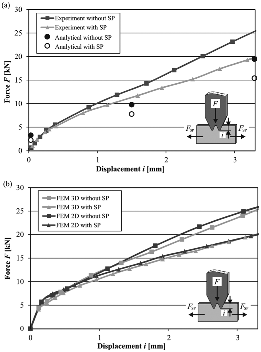
Force–displacement (indentation i) evolution for the incremental forming of gears by indentation along the direction perpendicular to the sheet thickness with and without stress superposition: (a) experimental results and analytical predictions at specific values of displacement obtained from the proposed analytical model and (b) experimental results and numerical predictions obtained from finite elements.
The estimates provided by the proposed analytical model at specific punch displacements (indentation depths) are included in Figure 7(a) as open and solid markers. The solid markers corresponding to the indentation depth that needs to completely form the gear tooth without stress superposition were calculated from equation (5), while the open markers corresponding to the indentation depth that needs to completely form the gear tooth with stress superposition were calculated from equation (7). Both results made use of a shear yield stress
The comparison between analytical and experimental results is fair (20% error at the maximum indentation depth
The two- and three-dimensional finite element–predicted evolutions of force with displacement (Figure 7(b)) reveal a very good agreement with the experimental results, as shown in Figure 7(a). Major deviations between two- and three-dimensional estimates of force at the end of the process are below 5% and may be justified by the fact that the two-dimensional finite element models are not able to model plastic flow into the 0.1mm clearance that exists between the sheet and the blank holder.
Nevertheless, the above-mentioned results allow concluding that the plane strain deformation assumption that was utilized in the development of the analytical model is adequate. Moreover, in case of finite element analysis, the plane strain deformation assumption also leads to a reduction in CPU time of approximately 96% (5 min against 130 min in a desktop computer equipped with an Intel i7-5600U (2.6 GHz) processor). All these reasons justify the utilization of two-dimensional models in subsequent finite element analysis.
Extent of the plastic deformation region
The analytical model based on the slip-line field of Figure 3(e) provides an estimate of the maximum expansion x of the plastic deformation undergone by the sheet during indentation by means of a gear tooth punch (refer to distance x in Figure 4(a))
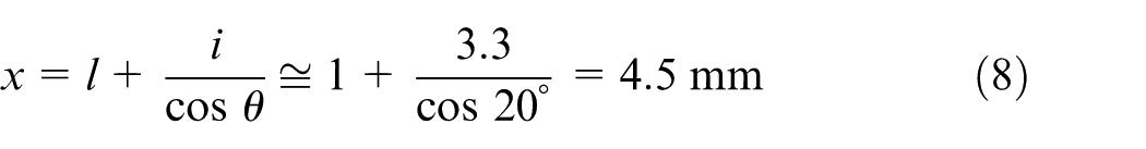
This estimate was checked against microhardness measurements (HV 0.1) performed on various points located at different distances and depths from the upper, outer surface of the punch wedge. The measurements were made in accordance with DIN EN ISO 6507-1:2005. 13
The overall result is shown in Figure 8 and allows concluding that the analytical estimate of the maximum expansion
Evolution of microhardness (HV 0.1) with the distance from the upper, outer surface of the punch wedge.
The above estimate from equation (8) is also relevant from a product point of view, because incremental forming of gears by indentation along the direction perpendicular to the sheet thickness is not only shaping the form but also influencing its mechanical and physical properties. 14
Sensitivity to superimposed stresses
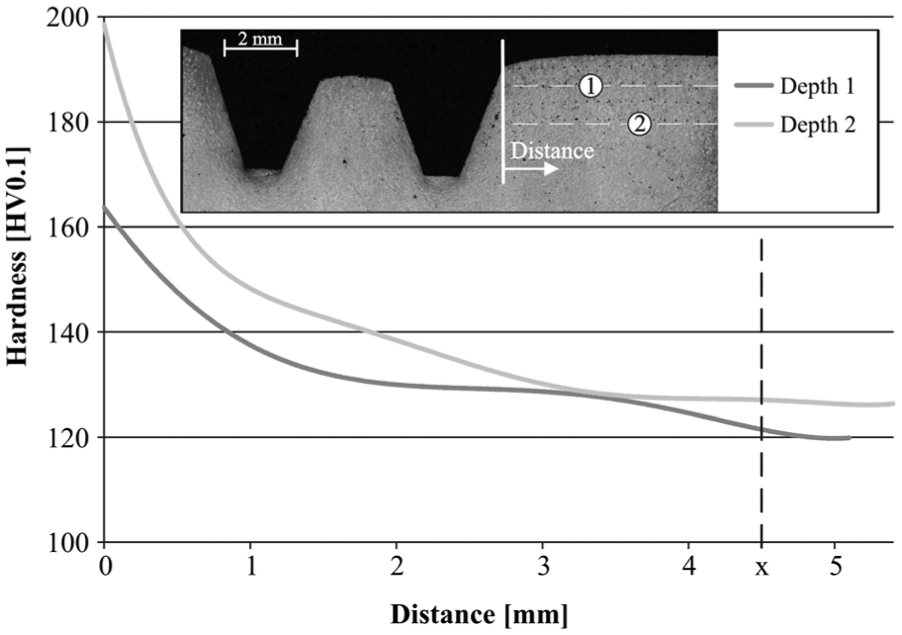
Taking into consideration the reduction in force F that is achieved by superimposing a tensile stress, it is interesting to determine the maximum expected reduction in force when the superimposed stress
Figure 9(a) shows the finite element–predicted effect of applying different superimposed tension forces
Incremental forming of gears by indentation along the direction perpendicular to the sheet thickness with superimposed stress: (a) finite element–predicted evolution of the force with displacement for different superimposed stresses and (b) analytical and finite element estimates of the maximum reduction in the indentation force as a function of the ratio between the superimposed stress and the yield stress.
The diagram in Figure 9(b) results from plotting the maximum reduction in the compression force F obtained from the finite element results shown in Figure 9(a) as a function of the ratio
Estimates obtained by means of equation (7) for different values of superimposed tensile stress
Conclusion
The indentation force for the incremental forming of gears along the direction perpendicular to the sheet thickness can be significantly reduced by superimposing tension stresses along the in-plane direction. These stresses must be smaller than the yield stress of the material in order to avoid plastic deformation of the sheet before applying the indentation force.
In the case study presented in the article, the reduction in the indentation force due to superimposing tension stresses can reach values up to 30% as it was shown by combination of experimentation, finite element simulation and analytical modelling.
Analytical modelling by means of the slip-line theory helps understanding the distribution of pressure along the inner and outer walls of the punch wedges and allows predicting the maximum extend of the plastic deformation undergone by the sheet during indentation. The later shows very good agreement with the maximum extends inferred from microhardness measurements taken at increasing distances from the gear tooth.
Footnotes
Acknowledgements
Paulo AF Martins would also like to acknowledge the support provided by Fundação para a Ciência e a Tecnologia of Portugal under LAETA – UID/EMS/50022/2013 and PDTC/EMS-TEC/0626/2014.
Declaration of conflicting interests
The author(s) declared no potential conflicts of interest with respect to the research, authorship and/or publication of this article.
Funding
The author(s) disclosed receipt of the following financial support for the research, authorship, and/or publication of this article: This work was supported by the German Research Foundation (DFG) within the scope of the Transregional Collaborative Research Centre on sheet–bulk metal forming (SFB/TR 73) in the subproject A4 ‘Fundamental research and process development for manufacturing of load optimized parts with incremental forming of thick sheets’.