
Abstract
The aim of this article is the investigation of the effects of tool tilt angle on the friction stir welding of aluminium to the steel butt joint. For this purpose, 1°, 2° and 3° tilt angles are selected to friction stir welding of AA1100 to A441 AISI, while the other process parameters (i.e. tool rotational speed, travelling speed, tool offset and plunge depth) kept constant. The results showed that with increasing tool tilt angle, the interaction between two metals and axial force increased. The increasing tool tilt angle caused more surfaces to mingle, internal mixing and frictional heat generation. The results of the microstructure of joints revealed that the AA1100 microstructure is more thermo-mechanically affected than A441 AISI. The AA1100 average grain sizes at stir zone were 1.2, 1.6 and 2 µm and at A441 AISI were 6, 7 and 9 µm at 1°, 2° and 3° tilt angles, respectively. The maximum tensile strength of joints was 75% of the aluminium base metal, which was produced at 2° tilt angle. The higher heat generation and axial force at upper tilt angle cause separation of the steel fragments on the aluminium matrix and formation of Al-Fe intermetallic compound. These phenomena lead to increase in the micro-hardness of the joint at the upper tool tilt angle.
Introduction
Compared to the other welding processes, friction stir welding (FSW) is a solid-state joining that enables to join dissimilar materials. This joining technique is a remarkably simple welding process. In FSW, a non-consumable rotational tool penetrates the joint line and makes the surrounding material pasty by generation of frictional heat and moves along the parting line. The FSW tool, during travelling, forwards the plastic materials from front to rear side with forging force and combines them. 1 The side of weld where the sense of tangential velocity of the rotating tool is parallel to the sense of the tool traverse is termed as advancing side (AS), and if opposite, retreating side (RS). 2 Existing disturbances and heat in FSW are causing changes in the impurities’ distribution and the grain size surrounding and the joint centre. Figure 1 presents a schematic view of the FSW process. Joining of dissimilar materials is becoming increasingly important for improved performance of engineering structures. 2 This progress made in welding lightweight materials, such as aluminium and steel, makes the mass production of light transportation system, and hence a significant reduction in fuel consumption. 2 In joining of aluminium and steel by fusing welding methods, due to high heat input into the junction, thick, brittle and hard compound layer is formed. This compound can damage the mechanical properties of the joints. 3 Therefore, in recent past, the researchers focus on joining of such materials by FSW process. They extensively used FSW for joining aluminium alloys to steel and studied mechanical properties, microstructures, material plasticization and so on.
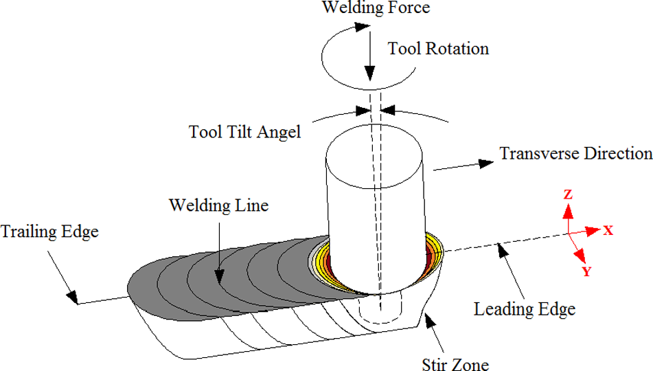
Friction stir welding process.
Jiang and Kovacevic 4 succeeded to join 6061 aluminium alloy to AISI 1018 steel by FSW process. The joint had desirable mechanical strength and they showed that the increase in tool rotary speed produced the defect-free joint. Elrefaey et al. 5 reported that in the dissimilar joint between commercial aluminium and low-carbon steel, joint strength depended on the pin plunge depth in the steel surface. Uzun et al. 6 investigated the properties of friction stir–welded 6013-T4 aluminium alloy to X5CrNi18-10 stainless steel. Watanabe et al. 7 conducted experiments on the effects of a FSW tool offset and tool rotational speed on the tensile strength and the microstructure of the SS400 mild steel and A5083 aluminium alloy. The maximum tensile strength of the joint was about 86% of that of the aluminium alloy base metal when 90% of the cross-sectional area of pin was placed in the aluminium side. Chen 8 performed a parametric study on FSW of Al6061-T651 aluminium alloy to low-carbon steel. They indicated that lower rotational and linear speed can result in higher impact values of weld strength. Their maximum tensile strength can reach 76% of the aluminium base metal. Dehgani et al. 9 investigated the effects of FSW parameters on mechanical properties of aluminium alloys to mild steel. They reported that the joint strength was more than 90% of the aluminium base metal reachable by controlling the intermetallic compound (IMC) and heat impact factor. Liu et al. 10 attempted to join 6061-T6 aluminium and transformation-induced plasticity (TRIP) steel. They reported that welding speed had an insignificant effect on mechanical welding force, temperature distribution, strain rate and intermetallic layer composition. On the other hand, higher rotational speed can elevate the temperature distribution, vertical and lateral force and can also influence the composition of the formed IMC layer.
Among the FSW parameters, the tool tilt angle (TTA) is a key factor to material flow and heat generation. 11 Figure 2 presents a schematic view of the FSW tool tilt illustration. Barlas and Ozsarac 12 evaluated the effects of the TTA on the FSW of AA5754 aluminium alloy. They reported that by increasing TTA, root flow in stir zone (SZ), which caused at 0° tilt, removed at 2°. Grujicic et al. 13 studied on the effects of the tool tilt on FSW of AA5059 aluminium alloy with the finite element method. They selected 2.0°, 2.5° and 3.5° tilt angles. According to their results, the tilt more than 2.5° has bad effect on the mixing and material flow. Kimapong and Watanabe 14 reported that with increase in the TTA, the shear strength of the joint decreases. The larger TTA formed a thick Fe2Al5 IMC at the joint interface, which directly related to the decrease in the joint shear strength. Ranjith and Senthil Kumar 15 also investigated the effects of TTA during FSW of AA6063 aluminium alloy and showed that the material skimming occurred when the tilt angle was low. Mehta and Badheka 11 reported that formation of thick IMCs occurs when tilt angle increases at Al to Cu joint. According to available references, the effects of TTA on the metallurgical and mechanical properties of dissimilar joint, especially on the aluminium–steel joint are not completely clear. Therefore, the aim of this article is comprehensive investigation of the effects of TTA on the mechanical and metallurgical properties of AA1100 aluminium alloy and A441 AISI steel FSW joint.
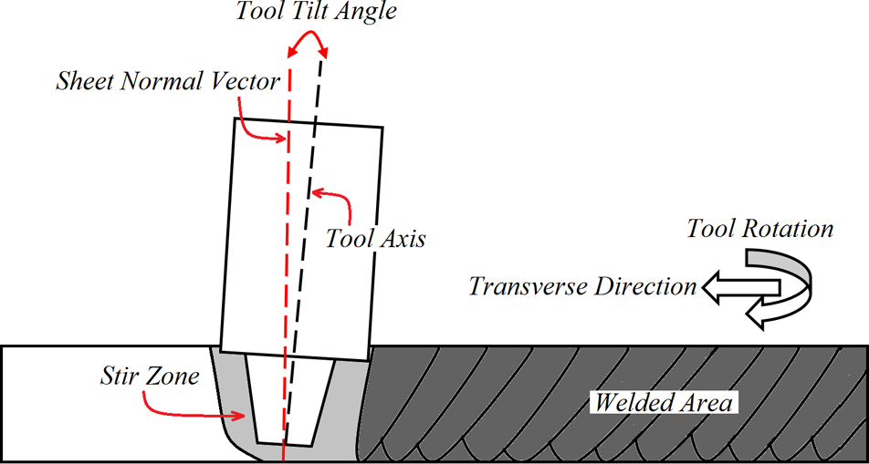
Friction stir welding tool tilt illustration.
Experimental procedure
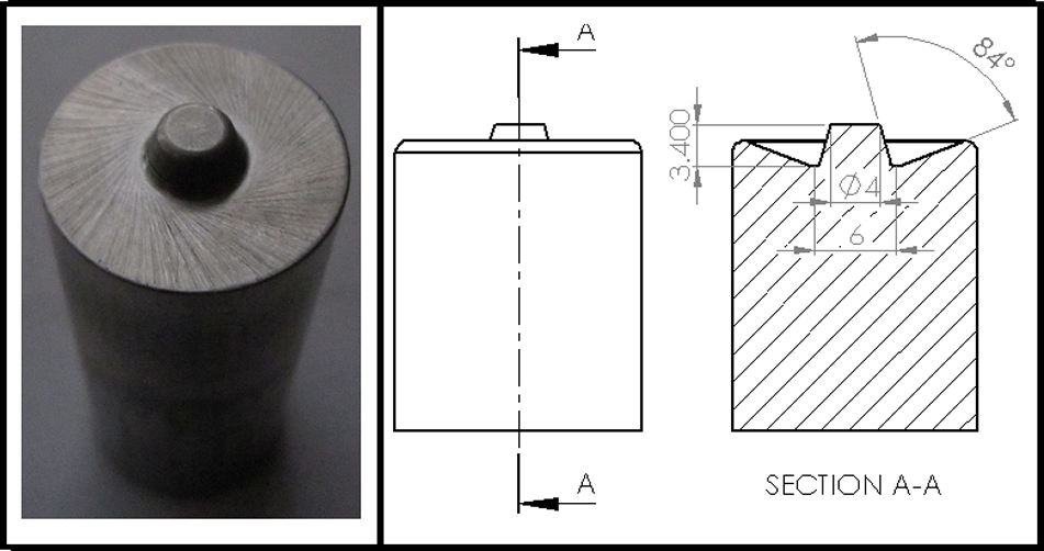
In this research, AA1100 aluminium alloy and A441 AISI plates with 3 mm thickness were cut into required sizes by a universal sawing machine. The mechanical properties of base metals are presented in Table 1. A flexible clamping system made of high-carbon steel was designed to secure the plates in their proper positions. Non-consumable tool with taper profile, made of tungsten carbide, was used to fabricate the joints (Figure 3). A TABRIZ/4301 milling machine modified with FSW tool attachment was used to fabricate the joints. In this experiment, steel sheets were located on AS.
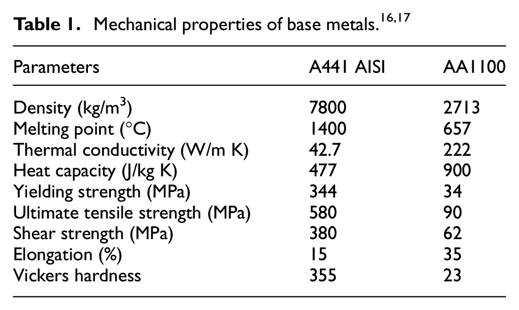
FSW frustum tool.
For conducting the experiments, a single-factor experimental design was used. It means that for finding effect of a given parameter, it varies through the levels, while the others are keeping constant. In this study, the tool rotation direction was counterclockwise (CCW) and had 1°, 2° and 3° tilt angles from the plate’s normal surfaces and 1.5 mm offset in the aluminium side. In the entire process of welding, tool rotational speed was 710 r/min, and linear speed that aluminium and steel sheets welded together was 40 mm/min. The tool plunge depth (shoulder distance from top surface of workpieces) was 0.2 mm. Three joints were welded by mentioned parameters for the better understanding of the effects of TTA. To study the welds’ behaviour in tensile test, three samples were cut from each joint according to ASTM E8-M03 standard. For measuring tensile and yield strengths, the tensile test specimens which were cut from welded joints have been gripped by grippers of 100 kN servo-controlled universal testing machine, and the values of tensile strength and yield strength have been measured. Also, the Vickers hardness (VH) of welded joints has been measured using Vickers’ micro-hardness testing machine (Make: Shimadzu; and Model: HMV-2T), and the machine with 0.05 kg load at 15 s was utilized to measure the hardness of weld nugget. The specimens for metallographic examination were sectioned to the required sizes from the joint comprising friction stir processing (FSP) zone and then polished using different grades of emery papers. Final polishing was done using the diamond compound (1 lm particle size) in the disc polishing machine. The polished samples were etched using 1% hydrofluoric acid (HF), 2.5% hydrochloric acid (HCl) and 1.5% nitric acid (HNO3) for aluminium, and 5% HCl and 95% ethanol to show general flow structure of the steel. Macro- and micro-structural analyses have been carried out using a light optical microscope (VERSAMET-3) incorporated with an image analysing software (Clemex-Vision). Furthermore, to analyse the material flow, the video visual measurement machine (VMM) was utilized. Also, for finding formation of IMC in weld region, energy-dispersive X-ray spectroscopy (EDX) and scanning electron microscopy (SEM) analyses were used. The K-type thermocouples were used to measure of the temperature which embedded at mid-plate thickness for both sides of the sheets. A groove was prepared in the middle of sheets that were supposed to be welded and one thermocouple was determined as origin. For more accurate study of heat flow, two more thermocouples were used. Each of them placed with 3 cm distance from the indicator thermocouple at aluminium and steel sides. The thermocouple set-up illustration is shown in Figure 4.
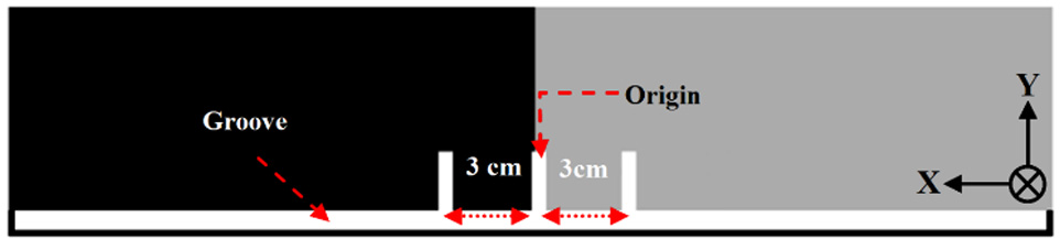
The thermocouple set-up illustration.
Results and discussion
Thermal history
A sample of temperature graph which is recorded by the thermocouple is shown in Figure 5.
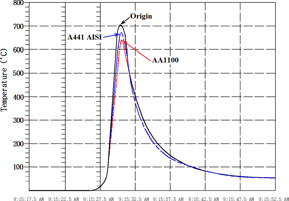
A sample of temperature graph.
The heat produced on the aluminium side is more than the steel side. The peak temperature recorded by the origin thermocouple indicates the temperature at SZ. The difference in heat production at AS and RS is seen at all tilt angles. These changes are related to the inequality of shear strength of two workpieces. The maximum temperatures produced at 1°, 2° and 3° TTAs were 682 °C, 685 °C and 700 °C, respectively, which is shown in Figure 6. The temperature growing trend by increasing TTA has strait relation with more axial force, which exerted on the workpieces. Increasing TTA causes more plastic deformation and downward forging force, which lead to higher heat generation. 11 The recorded temperatures show that by increasing TTA, the heat generation in the steel side has a greater uptrend compared to the aluminium side.
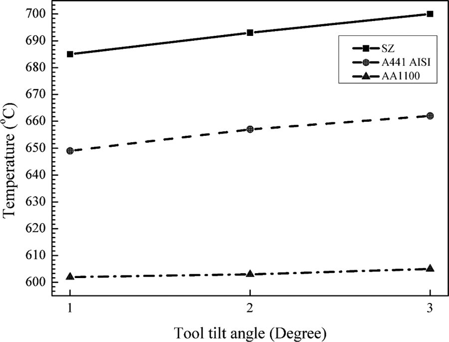
Measured temperatures at different TTAs.
Surface material flow and macrostructure
The effect of TTA is one of the process parameters that has a great impact on FSW process characteristics. This parameter directly affects the flow of the plasticized material around the shoulder. 11 With an increase in TTA, downward forging force and heat generation rate increase, correspondingly. But, one of the limiting factors in the TTA is that the tool pin may penetrate into the bottom of the sheets and damage the welded sheets. Figure 7 presents the flow of plasticized material under various TTAs. From Figure 7, it is observed that the joints fabricated at the 1° tilt angle have a bulbous shape with widely spaced stripes. In this TTA, welding axial force did not move enough material and caused the formation of irregular material flow. According to the dimensions of the plates, in the 2° TTA, the downward forging force was increased and consequently, the material extrusion from the front of the tool shoulder increased to the rear of the tool. For this reason, at 2° TTA, the surface flow is improved and distance between the formed rings becomes less. Better forging force produced a better surface finish and the surface roughness of the welded area reduces, correspondingly. At the tilt angle of 3°, although the forging force increases, the vacant space at the back of the tool increases, and during the process, material flow becomes irregular and non-uniform material distribution occurs on the flow surface. With increasing TTA and downward forging, the body of the tool will plunge more to the workpieces and does not permit the extruded material to enter the SZ. At high TTA, dents, wrinkles and surface voids are observed in the welding region.
Surface material flow at different TTAs.
Figure 8 exhibits images of texture patterns on the transverse cross section of various welds. In all these images, the A441 AISI is on the left, and the aluminium alloys are on the right. The shapes of the welds are analysed, where the macro-sections reveal a zone comprising the so-called nugget zone, thermo-mechanical-affected zone (TMAZ) and heat-affected zone (HAZ) which is visible in the aluminium side. In the steel side, only HAZ is formed.
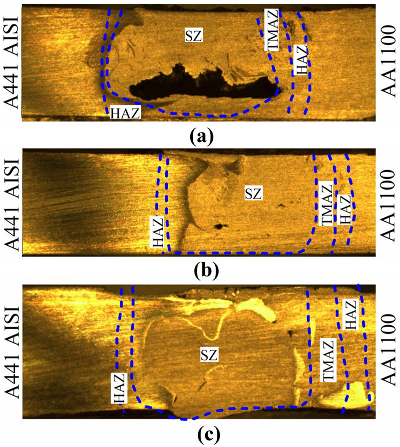
Internal material flow at different TTAs.
Major tunnel defect was observed for tilt angle 1°, whereas defect-free macrostructures were noticed for tilt angles 2° and 3°. This was due to the increase in heat generation and compressive force, which helps in mixing of steel particles in the aluminium matrix.18,19 At higher TTA, the steel particles were distributed randomly in aluminium matrix like the island as shown in Figure 8. Higher tilt angle pushes the material downwards and allows steel particles to flow freely in the aluminium matrix which helps to achieve good metallurgical bonding between A441 AISI and AA1100. Additionally, the shape of the SZ was also varying in different TTAs. The SZ becomes bigger as tilt angle increases from 1° to 3°. As tilt angle increases from 1° to 3°, the bottom SZ kept increasing and simultaneously the top area of the joint was also increasing. This change in shape of the SZ proved that vertical and horizontal material flows in SZ also change. At 1° tilt angle, insufficient vertical and horizontal flows of the weld material may have caused tunnel defects in SZ. Increment in the TTA improves the flow characteristics of the SZ material, hence this tool tilting forges the weld material better to fill the defects. It was proven earlier that thermal conductivity of the steel is less than that of the aluminium, so thermal softening of A441 AISI will be stronger.16,17 Therefore, under the temperature and loading cycles in the process, the soft steel will be pushed away from the area below the shoulder by the aluminium entering there at each rotation. At 2° tilt angle, the stretching of AA441 AISI became more and with increasing tilt angle, the steel was peeled from AA441 AISI edge and separated to the aluminium matrix.
Microstructure of joint
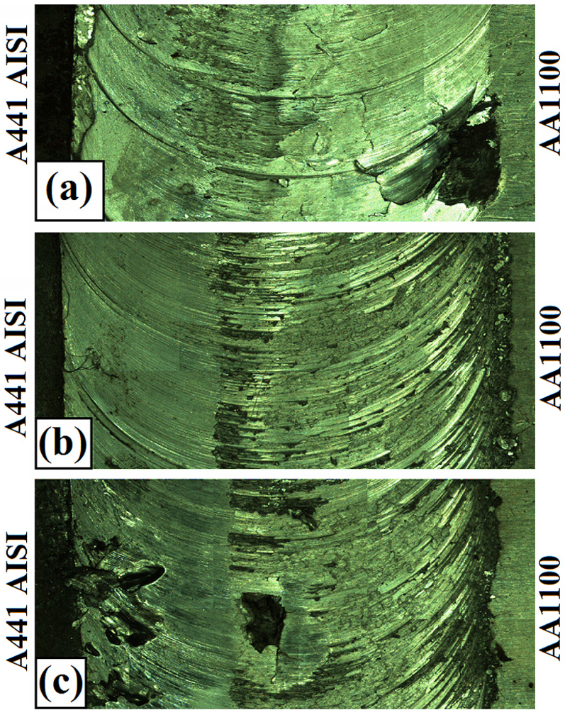
In this study, the maximum temperature was about 700 °C for 3° TTA which was far away from the melting temperature of A441 AISI base metal. But, this temperature is over of AA1100 melting point. During the experimental test, no sign of melting was observed. It seems that this temperature produced is locally undersized. Figure 9 shows micrographs of the SZ for both alloys at different plunge depth. In addition to a thermal cycle, the SZ also will endure a mechanical cycle. In spite of the high strain rate, recorded temperature and pictures from SZ, it can be suggested that the A441 AISI steel structure was under discontinuous dynamic recrystallization (DDRX) at SZ. No changes in the steel microstructure were observed at 1° TTA. With increasing heat generation and plastic deformation at 3° TTA, A441 AISI microstructure in the SZ transformed to tiny austenite, and after cooling, converted to the small grains of ferrite and pearlite. The reason for this may be attributed to higher axial plunge load recorded with increasing tilt angle. 13
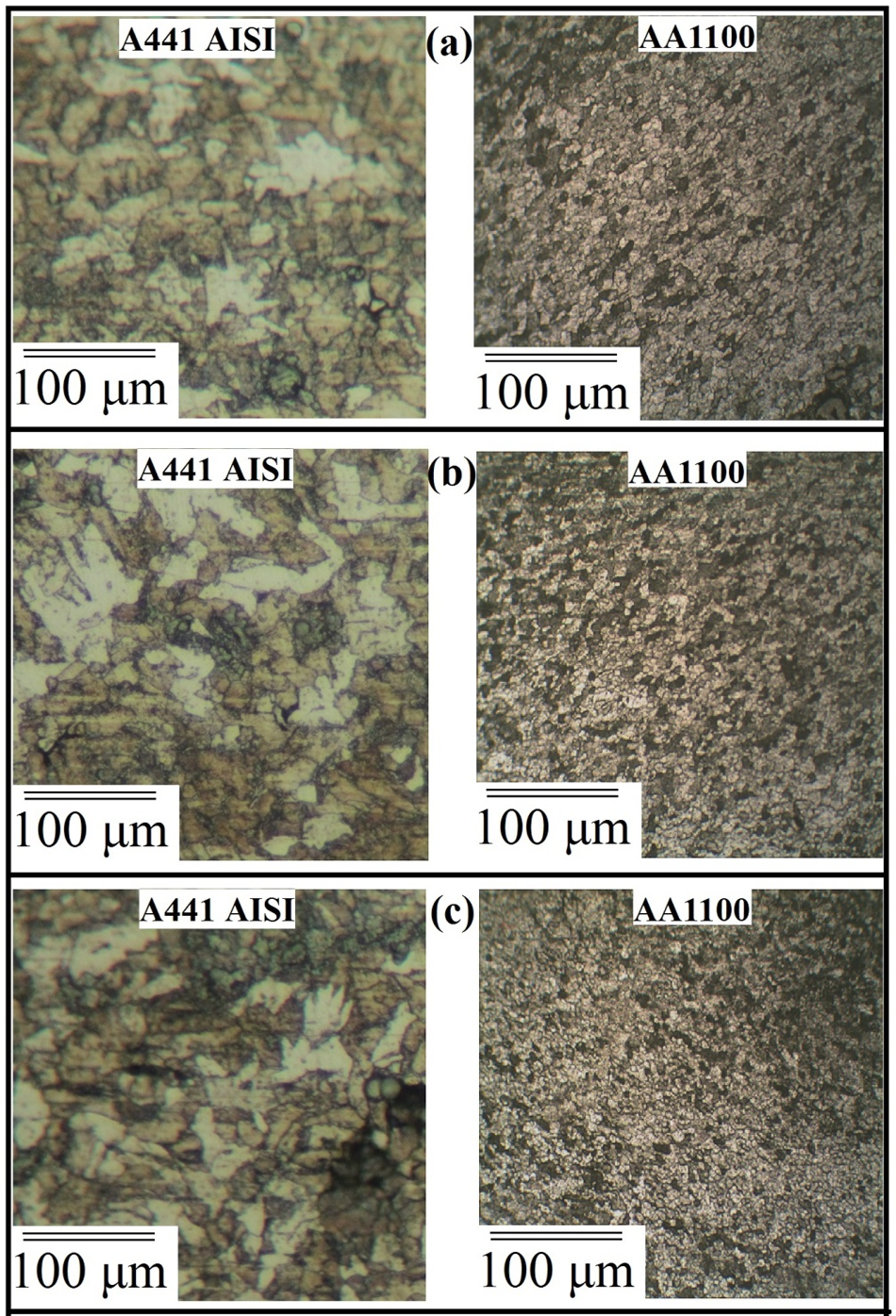
Microstructure of joint at (a) 1, (b) 2 and (c) 3 degree tool tilt angle.
In general, due to softness and low shear stress of AA1100 aluminium alloy, the material in the SZ is affected by high temperature and intense plastic deformation. These microstructure changes were exacerbated by increasing the TTA on the AA1100. According to result, the AA1100 was subjected to high temperature and plastic deformations when compared with A441 AISI. The results show that the average grain sizes at AA1100 side in SZ were 1.2, 1.6 and 2 µm at 1°, 2° and 3° tilt angles, respectively. The optical microscope results show that with increasing tilt angle and plastic deformation, small grains are produced more in upper area of SZ than the lower area of the joint in the steel side. There is a bimodal distribution of large and small ferrite grains in upper area of joint which welded at 3° TTA, whereas this situation is not visible to the joint which welded at 1° TTA region. The average ferrite grain sizes of this region in the 1°, 2° and 3° tilt welds are 6, 7 and 9 µm, respectively. The different heat conductivities of both the sides in the weld SZ may be the reason that has induced different structures. Higher heat conductivity of steel compared to aluminium leads to more frictional heat. Heat produced by stirring action on the aluminium side is lost in the nearby metal than the steel side. This brought to temperature reduction in this region and resulted in different structures in different sides of SZ.
Tensile properties of joints
The results of tensile test and tensile specimens after the test are shown in Figure 10. The ultimate tensile strengths of joints which welded at 1°, 2° and 3° TTAs were 62, 71 and 64 MPa, respectively.
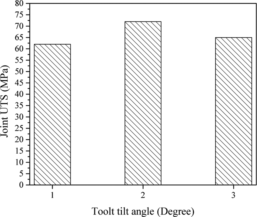
Ultimate tensile strength at different TTAs.
For better understanding of the joint strength compared to base metals, a factor is defined, which called joint efficiency (JE), written as follows
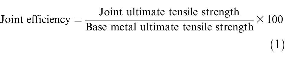
Figure 11 presents the JEs of welded samples at different plunge depth that are compared with AA1100 base metal. It can be inferred from the figure that the JE increases by increasing the plunge depth and reaches to a maximum value at 2° TTA. Then by the further increase in values of TTA (i.e. 3°) the JE decreases correspondingly. When the plunge depth is relatively low, the JE reaches to 68% of the aluminium base metal. Formation of internal and surface defects in the weld that produced at 1° TTA reduces the strength of the joints. At 2° TTA, the JE is about 75% of the aluminium base metal strength. Due to appropriate mix between the two base metals, the separation of the joints in tensile strength test was in the aluminium base metal. Due to high axial force and propulsion of the material in the SZ, intermix of AA1100 and A441 AISI is not as well in 3° TTA.
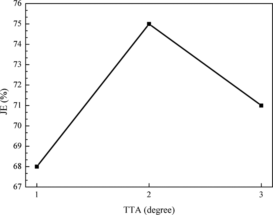
Joint efficiency at different TTAs.
The tensile test presents valuable information about welding quality and its strength. After tensile test, specimens’ fracture locations can be in tight relationship with process parameters. In these tests, fractures occur in SZ and TMAZ (Figure 12).
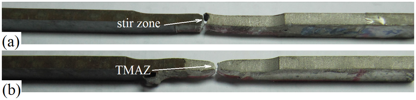
The tensile test samples which fractured at (a) stir zone and (b) TMAZ.
The separation path in each tensile test was different places. The fracture path at the joint which welded by 1° tilt angle was placed in the SZ. With the increase in tool tilt up to 2° and 3°, downward forging force increases, correspondingly, and the AA1100 and A44 1AISI joints were broken in the TMAZ in tensile test. The schematic view of the fracture path in the cross section of joints is shown in Figure 13.
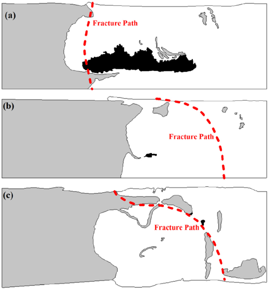
The fracture path after tensile test which occurred at (a) 1° (b) 2° and (c) 3° tilt angle samples.
Macro-hardness of joint
Results of macro-hardness variations for different tilt angles are shown in Figure 14. It was noted that the macro-hardness value in the nugget area was increasing as the tilt angle increases from 1° to 3°. Maximum macro-hardness of 300 VH was observed in the SZ at tilt angle 3°, while minimum macro-hardness of 260 VH was observed in the SZ at tilt angle 1°.
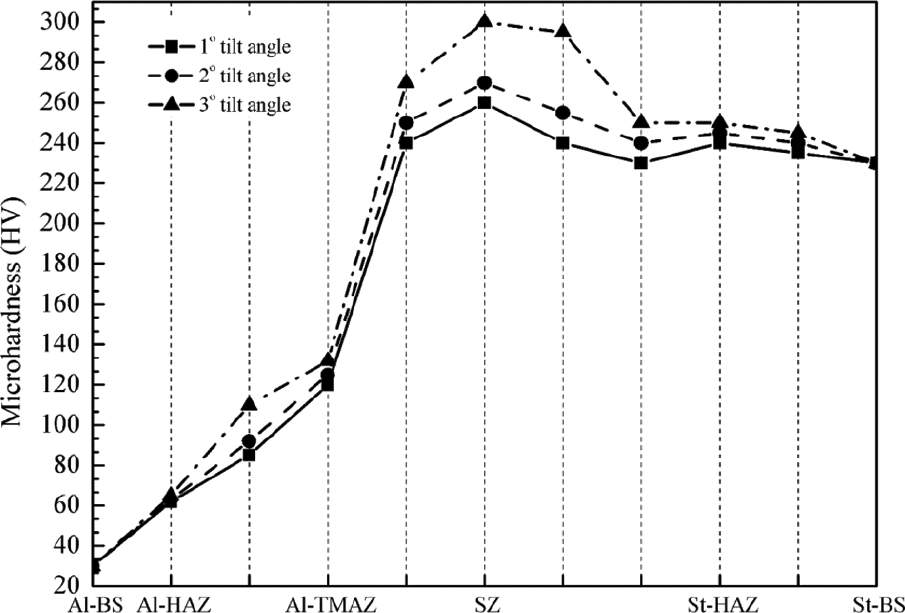
The micro-hardness of joint at different tool tilt angles.
The increase in the macro-hardness values in these regions can be attributed to dynamic recrystallization, which has occurred during the welding process or because of the presence of IMCs. 9 Presence of IMCs identified by SEM is as shown in Figure 15 for tilt angles 1° and 3°, respectively. Formation of IMCs increases as tilt angle increases because of the rise in the overall heat generation and extrusion of base metals into the SZ. 9 These changes at two sheets interface are main reasons for the increased hardness of the joints. These results are coherent with the previous studies which reported that increase in heat input produces large IMCs. 9 The macro-hardness increases as tilt angle increases, which is because of the rise in the formation of IMCs in the SZ. Intermetallic layer thicknesses in joints which were fabricated with 1°, 2° and 3° TTAs are 1.5, 2 and 4 µm, respectively. The EDX analysis results show that the TTA is effective in the chemical composition of IMCs. Higher TTA will increase the weight percent of aluminium and steel in the SZ. The results showed that the chemical composition of formed IMCs on the 1° and 2° is FeAl3 and in 3° is FeAl2.
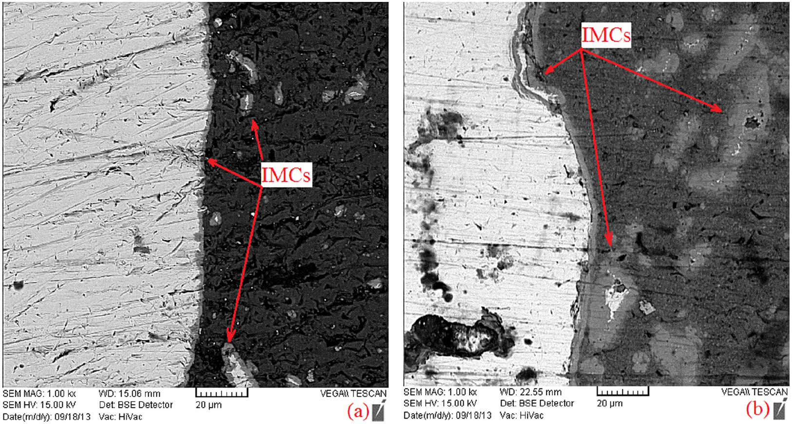
IMCs which are formed at (a) 1° and (b) 3° joint interfaces.
Conclusion
The effect of TTAs on the mechanical and metallurgical properties of A441 AISI to AA1100 FSW joint was investigated experimentally. The following conclusions can be made:
The thermal history of joints shows that with increasing TTA from 1° to 3°, the heat generation trend increased. The maximum produced temperatures at 1°, 2° and 3° tilt angles in the FSW of AA1100 aluminium to A441 AISI joint at SZ were 682 °C, 685 °C and 700 °C, respectively.
With the increase in TTA at 3°, downward forging force, tool plunge and heat generation rate increase. Due to excess and inappropriate increase of TTA, the extruded materials from front of tool collide with tool body in the surface of workpieces and will be unable to fill the SZ. On the other hand, with increasing TTA at 3°, the internal flow in the stir and welding zones increased. With increasing TTA in the stretch of steel to the aluminium matrix, more A441 particles separated in the SZ.
At the higher tilt angle, the material in the SZ suffered more temperature and plastic deformation, which caused more change in SZ. With increasing downward forging force, material extrusion and frictional heat at high TTA and the microstructure changes in SZ became more. The average grain sizes at AA1100 side in SZ were 1.2, 1.6 and 2 µm and were 6, 7 and 9 µm at A441 AISI side, respectively.
According to selected TTA in this study, the maximum joint strength was produced at 2° tilt angle with 71 MPa and 75% JE of the aluminium base metal. At further tilt angles, the fracture path shifted from SZ, at 1° tilt angle, to TMAZ, at 2° and 3° tilt angles. Greater interaction between aluminium and steel at higher tilt angle causes formation of IMCs at sheets’ arbitrary edge. The macro-hardness increases as tilt angle increases, which are because of the rise in the formation of IMCs in the SZ. The EDX results showed that the chemical composition of formed IMCs on the 1° and 2° is FeAl3, and in 3° is FeAl2.
Footnotes
Declaration of Conflicting Interests
The author(s) declared no potential conflicts of interest with respect to the research, authorship, and/or publication of this article.
Funding
The author(s) received no financial support for the research, authorship, and/or publication of this article.