
Abstract
Automation, driven by informatics, enables manufacturing companies to increase productivity and meet market demands for cost-effective and high-quality products. However, many manufacturing operations across industry verticals continue to be manual even today. One such example is the manual assembly of the final trim and wheels in an automotive production line where there is heavy reliance on human decision-making pertaining to when, where and how to install components on and inside a constantly moving vehicle body. The main aim of this work is to develop a rule-based decision support system that will enable an automation solution to make human-like decisions in moving assembly operations. The wheel loading operation is chosen as a case study and a decision support framework and tool is developed and successfully tested using multiple assembly scenarios generated from experimental data provided by gaming interface sensors installed on the laboratory-based shopfloor. The resulting decision support system has the potential to enable the automation of moving assembly operations in various sectors of the manufacturing industry.
Keywords
Introduction
Rising global competition necessitates the increased use of automation in the manufacturing industry. This view is reflected in a recent survey conducted by Cranfield University in the United Kingdom, which found that more than 50% of UK manufacturing companies consider ‘investment in automation’ as one of the most important factors for productivity enhancement. 1 This is especially true for the highly competitive automotive industry, which is one of the most automated industries, but still retains a few critical manual operations. 2 An example of such an operation is wheel loading in the trim and final vehicle assembly line. Although the operation would seem straightforward for a human operator, it is one of the most complex moving assemblies to automate. The operation requires accurate motion tracking of the vehicle body on the conveyor line and real-time recognition of alignment features within the wheel and the wheel hub mounted on the vehicle body for successful assembly. Chen et al. 3 have indicated that the wheel loading operation alone can cost automotive manufacturers up to US$1.5 million (annualised), thereby justifying the need for automation of this operation.
Previously, researchers have attempted the automation of the wheel loading operation by developing robotic systems for loading a wheel on to a moving vehicle body. Early works in automation of moving assemblies proposed the use of conveyor motion tracking using data from the motion encoders and synchronising it to the assembly robot motion.4,5 Recent examples include the use of standard RGB vision systems to track vehicle body in motion on the conveyor line and detect alignment features and the use of force sensors for loading control. 6 Chen et al. 3 have reported a method of visual servoing to track the motion of the vehicle body in two axes to determine the wheel-loading instance and position. Schmitt and Cai 7 report the use of monocular camera mounted on the assembly robot end effector to track the moving object and estimate its motion trajectory in order to guide the motion of the assembly robot. Another example is the use of depth imagery for dynamic alignment control for an automated wheel loading operation. 8 This article reports the use of Microsoft Kinect, 9 a consumer-grade, low-cost sensor to replace the more expensive RGB vision systems and force sensors. In all previous research attempts, the live data captured by vision systems, depth imaging and force sensors are used as an alternative to human senses in the automated operation to make ad-hoc, situation-specific decisions without the real-time flexibility and adaptation of human decision-making that caters for dynamic assembly adjustments.
There is little evidence in literature to suggest that any of the reported automation solutions for moving assembly operations have used a structured human-like decision-making process. Therefore, the aim of this work is to develop a decision support system (DSS) framework and a DSS software tool guided by the human decision-making process. The DSS tool uses simulated shopfloor data acquired by gaming interface sensors to make assembly decisions. This unique solution has the potential to replace human decision-making in complex moving assembly operations, thereby enabling automation of these operations.
This article is organised as follows. In the next section, the related research is introduced. A method for developing the DSS framework is described in section ‘The proposed method’. The DSS tool and the experimental results from multiple assembly scenarios are presented in section ‘Results’ and discussed in section ‘Discussion’. Finally, section ‘Conclusion’ concludes this work and discusses future works.
Related research
A DSS helps to solve a complex problem in a structured manner. Such systems have been proposed and developed for various applications in manufacturing. Cheng and Chen 10 used the Markov decision process (MDP) that allows one robot to teach a task to another robot in an effort to automate production using a Markov-based decision-making process. However, the Markov assumption means that the next system state depends only on the previous system state without any feed forward to assist in decision-making. Dynamic environments such as moving assemblies need to take into account the eventual (future) system goal in addition to the past system states and the current system constraints to make real-time assembly decisions. Bozma and Kalalıoğlu 11 proposed non-cooperative game theory for the multi-robot coordination problem on a conveyor line. The non-cooperative game theory allows robots to make individual decisions based on minimising their individual cost function and observing the conveyor line characteristics and neighbouring robot actions. Leung et al. 12 used genetic algorithm and case-based reasoning as a scheduling tool for real-time information sharing and decision support in the mould-making industry. Mei et al. 13 proposed a decision-making analysis method for a robot to identify, locate and pick up objects moving on the conveyor, especially those that are not in the expected order. The decision to pick an object is made based on the identified coordinates and orientation of the moving object in the image stream of a charge-coupled device (CCD) camera and the displacement data from the servomotor of the conveyor using simple ‘if-then’ logic constructs. In these three methods, human cognitive behaviour while solving problems is not used as the basis for decision-making. Delen and Pratt 14 propose a multi-faceted knowledge-based system to develop an intelligent DSS for manufacturing systems. This DSS helps manufacturing managers to make decisions by structuring manufacturing problems, such as production scheduling, into executable models, such as Petri Nets, for analysis and decision-making. Shim et al. 15 discussed the early optimisation-based decision support models where the optimisation focused on generating a better solution algorithm in the formulation, solution and analysis functions of a model-based DSS. In both these solutions, a model that closely represents a manufacturing system must be available for analysis and therefore cannot be used for real-time decision-making where the system parameters keep changing.
There are several studies reported in the literature where a variety of methods such as neural networks, genetic algorithms, fuzzy systems, game theories, rule-based systems and a mix of these methods are used to design and develop DSS to solve classical manufacturing problems. These problems, however, pertain to operational issues such as planning and scheduling, quality control, systems design, selection of automation solutions and factory layout design. Particularly, Yang et al. 16 have used a combination of multi-objective function genetic algorithm and the bisection method to predict the optimal loading path for tube hydroforming. Very few papers have reported the development of DSS for automating actual manufacturing processes such as machining, assembly and inspections.10–12 For example, Tapoglou et al. 17 have developed a cloud-based multi-objective optimisation solution for selecting the machining parameters based on real-time monitoring of the part. Makris et al. 18 have developed an algorithm for deciding the sequence of instructions to be shown for assembly support based on the given assembly sequence, semantic classification of the sub-processes and components and the real-time task flow. In electronics manufacturing and assembly, Valendia et al. 19 have developed a database system using Structured Query Language (SQL) to support an integrated modelling framework definition for printed circuit board (PCB) assembly that can provide decision support to business processes throughout the product and process life cycle. Wang 20 has integrated the Taguchi method of experimental configuration with multi-attribute decision-making methods to choose the optimal parameters for surface mount solder printing process. Even fewer articles are found to have proposed a DSS for automation of moving assembly operations based on human cognitive process of problem solving, such as Mayer et al. 21 who have reported robotics assembly solutions based on the SOAR cognitive architecture.
It is evident from the above review that there is a lack of DSSs reported in the literature for automating moving assembly operations that are based on the human cognitive problem solving process. This first-of-its-kind work attempts to develop a DSS based on Rasmussen’s 22 decision ladder, a popular architecture that explains human problem solving process in industrial settings and on the work done by Prabhu et al., 23 to provide real-time data of moving assembly components on the shopfloor using gaming interface sensors. The use of the decision ladder provides the proposed DSS with the key characteristics of flexibility and adaptability that is associated with human decision-making in a dynamic industrial environment.
The proposed method
The main aim of this work is to develop a rule-based DSS for making human-like decisions in moving assembly operations, paving the way for automating such operations. In this work, the automotive wheel loading operation is selected as a use case and DSS framework and tool is developed and tested. Prabhu et al. 8 have proposed an automation solution in which depth imaging sensors are used to capture relevant data from the assembly shopfloor, such as the motion characteristics of the vehicle body moving on the conveyor line and the alignment features of both the wheel hub, on which the wheel is installed, and the wheel for successful loading. It was demonstrated in that work that the critical work done by human senses in a manual operation could be accomplished by low-cost sensors, thereby taking a big step towards automating the operation. However, unless the automation solution is as adaptable and knowledgeable about the operation as much as the human operator, it will not be able to solve dynamic real-time problems, sometimes unforeseen, during the operation.
This article proposes a DSS that mimics the cognitive process of problem solving followed by humans in industrial settings proposed by Rasmussen in his ‘decision ladder’ concept. A framework for decision support is developed by identifying the underlying concepts of when, why and how of human decision-making during critical operations. Based on this framework, operational requirements are gathered such as the assembly data and factors that affect the assembly operation and a decision support tool is developed. This tool is implemented using experimental data collected by depth imaging sensors from a simulated laboratory-based wheel loading workstation and is tested against multiple wheel-loading scenarios.
The underlying human decision-making concept
To mimic human decision-making, the underlying concept of cognitive human decision-making must be understood. In literature, there are two popular concepts, namely, Rasmussen’s decision ladder and Klein’s 24 recognition-primed decision (RPD) model. A comparison study by Naikar 25 of these two concepts reveals that although both the concepts are based on observation of expert decision-making in operational settings, Rasmussen’s decision ladder is better suited for adoption in this work. This is because unlike Klein’s RPD, the decision ladder represents human problem-solving in not only familiar conditions but also unfamiliar conditions under different scenarios, independent of the competencies of the human operator. Furthermore, the decision ladder is a simple concept that represents the human cognitive decision-making process in a manner that can be digitised and its adaptability to a variety of manual tasks irrespective of the task complexity.
Rasmussen, from an observation of human problem-solving behaviour in a power plant control room, argued that human decision-making process is a sequence of steps, represented by a decision ladder. The process starts with the operator being alerted to a problem, followed by collection of information to understand the current state of the system and diagnose the problem. Evaluating the various task options available to solve the problem and keeping the eventual goal of the operation in mind, the operator selects a task and predicts the consequences of that task vis-à-vis the target state. If the consequences are positive, then the chosen task is planned and executed to reach the task goal.
In the wheel loading operation context, the ultimate goal of the decision-making process is to perform wheel loading on a moving vehicle body. Rasmussen’s decision ladder is interpreted and adopted (Figure 1) to represent this operation. The process begins with the human operator being alerted by detecting the incoming vehicle body for the wheel loading operation. This is followed by gathering of key data associated with the operations such as vehicle model recognition, conveyor motion characteristics, alignment feature recognition and fault detection to diagnose and interpret the state of the operation in different phases. The task options for successful loading of the wheel are generated (such as load/abort, correction of alignment between wheel and wheel hub, loading position and time and loading force) and the consequences of these options on the success of the operation are evaluated/predicted keeping the overall goal of the operation in mind. Having made the appropriate decisions, the chosen task and its process is planned and eventually executed.
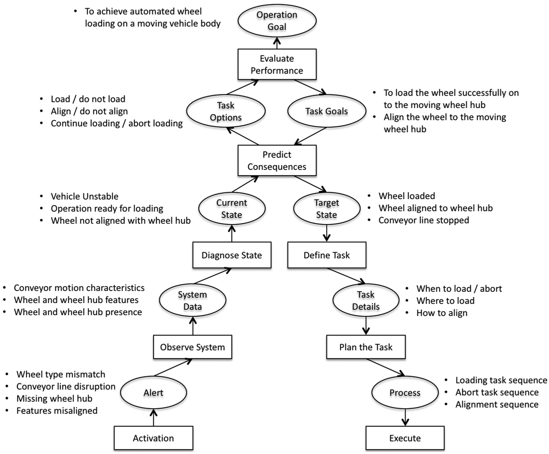
Decision ladder for the wheel loading operation. 19
In the decision ladder, the rectangles represent information processing activities, whereas the ellipses represent resulting states of knowledge. The information processes drive the decision-maker to ‘climb up the ladder’ on the left-hand side from identification to evaluation and continue to ‘climb down the ladder’ on the right-hand side to reach the target state, summarised by the ‘know-evaluate-decide-execute’ sequence.
DSS framework
A framework representing the above decision ladder is developed to provide a structure to the DSS tool. Such a framework will ensure that the resulting DSS uses the underlying cognitive decision-making concept. This will allow the DSS to cater to all scenarios and problems that can be foreseen during the moving assembly operation, which in this case is the wheel loading operation. The wheel loading operation comprises seven main phases. The framework is structured in such a way that in each phase, the decision-making process follows the ‘know-evaluate-decide-execute’ sequence of the decision ladder (Figure 2).
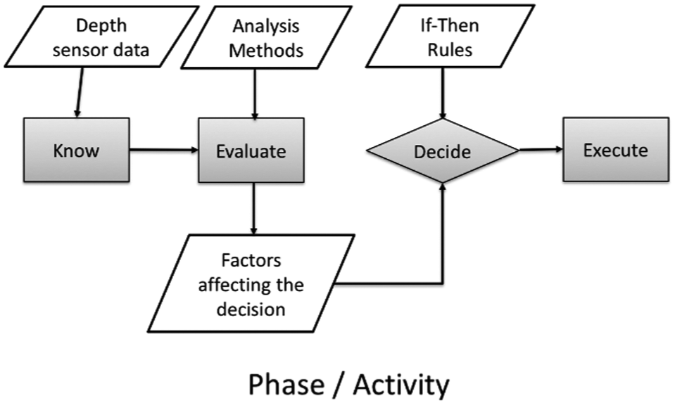
The decision-making process within each phase of the wheel loading operation.
The framework is functionally structured into five main elements, namely, input, activities, output, controls and tools. The seven phases of the wheel loading operation are the seven ‘Activities’ within the framework, the entities that influence the resulting decisions are the ‘Controls’ and the hardware and software entities that provide input or are affected by the decisions of the DSS are the ‘Tools’. In each activity, decisions that affect the operation (‘Outputs’) are made on the basis of information available to that activity via ‘Inputs’ provided by the depth imaging sensors from the assembly shopfloor. This is the ‘Know’ part of the decision ladder in which the DSS learns the current state of the operation in an activity.
The factors affecting the current state of the operation are computed from the input sensor data. For example, the speed and acceleration of the moving wheel hub are computed from the spatial motion and time data obtained from the depth sensors. This is the ‘Evaluate’ part of the decision ladder. These factors are then used to compare the current state of the operation and the expected state of the operation. Using ‘If-Then’ rules the various task options are analysed to select the most appropriate tasks/controls that will bring the operation to the expected or target state in that activity. This is the ‘Plan’ part of the decision ladder in which the actual decisions are made.
Once DSS makes the decisions for an activity, the selected task is executed as guided by the decisions. This is ‘Execute’ part in which the corresponding control commands are issued to the appropriate tool, the wheel-loading robot in this case study. The DSS then moves on to the next activity as the vehicle body moves on and this continues until all the seven activities are completed. The framework is shown in Figure 3.
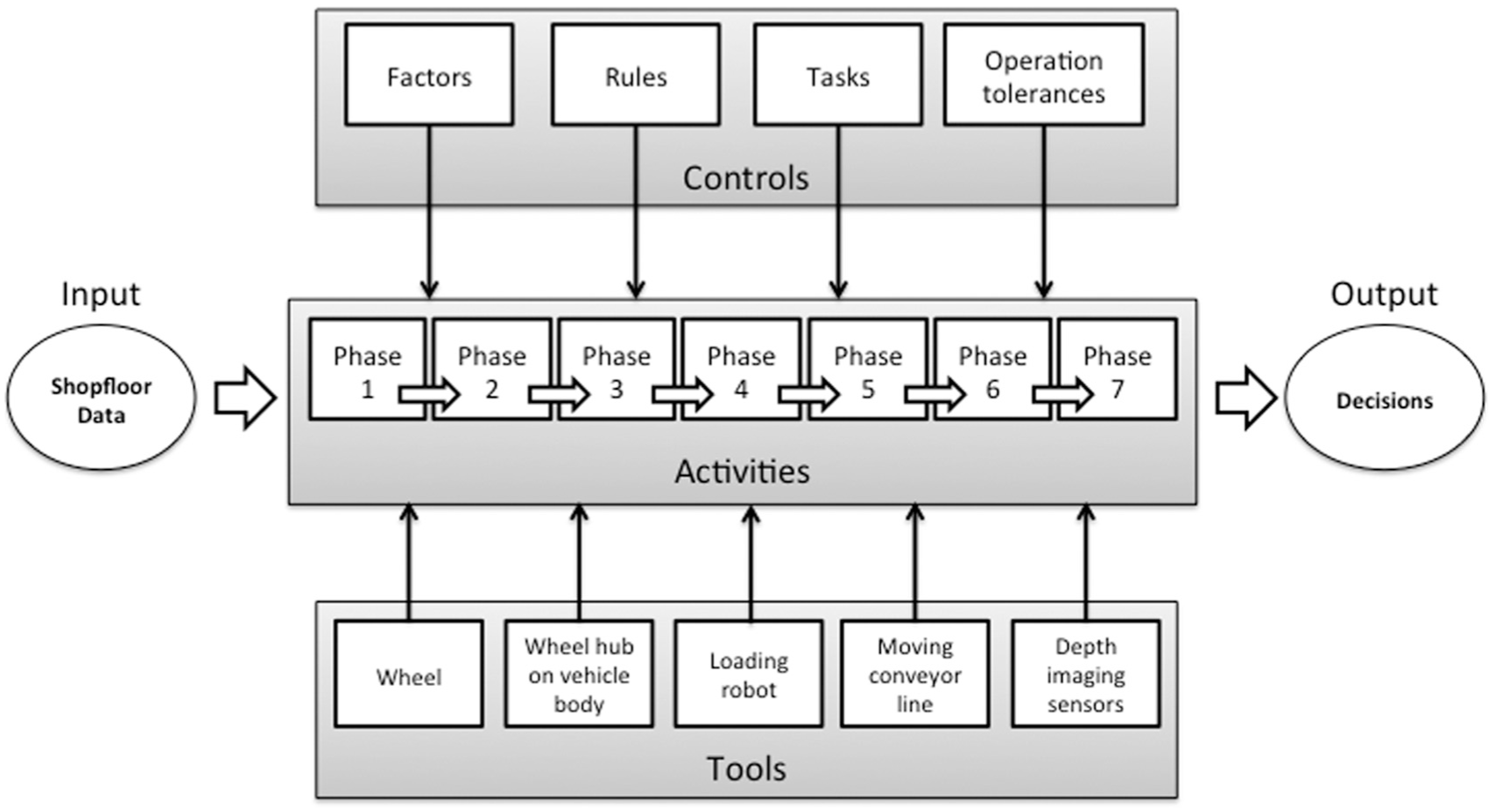
DSS framework for automated wheel loading.
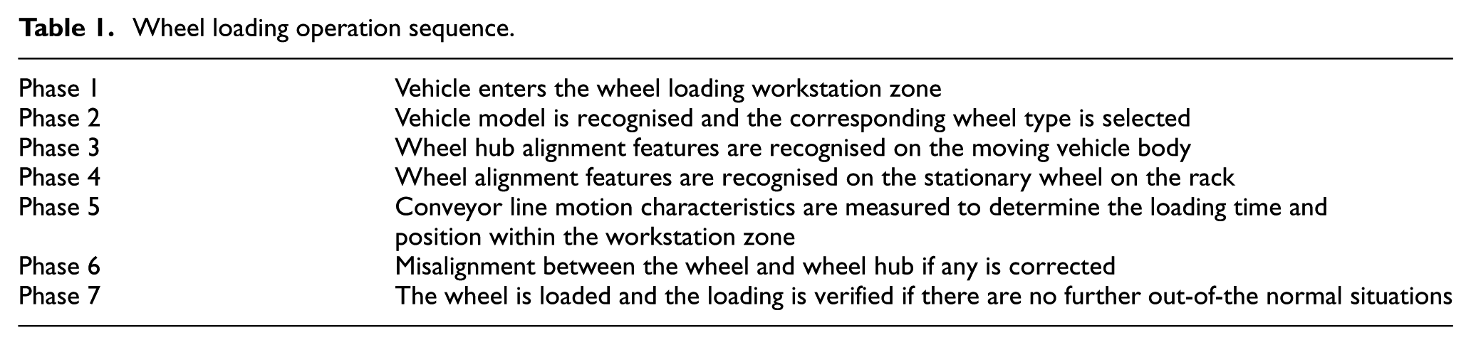
The seven phases of the wheel loading operation are represented in the proposed DSS framework according to the sequence of the actual wheel loading operation (Table 1).
Wheel loading operation sequence.
Factors that influence decisions
Each phase of the wheel loading operation is associated with a set of factors that are critical for the success or failure of that phase, thus influencing the success or failure of the operation as a whole. Therefore, the decisions made during each phase are based on these critical factors that are computed from the input data received from the sensors during that phase. These factors when clubbed with a set of stored expert rules are used to make decisions. A full list of factors associated with each phase of the operation is shown in Figure 4 along with the corresponding inputs and outputs for each phase.
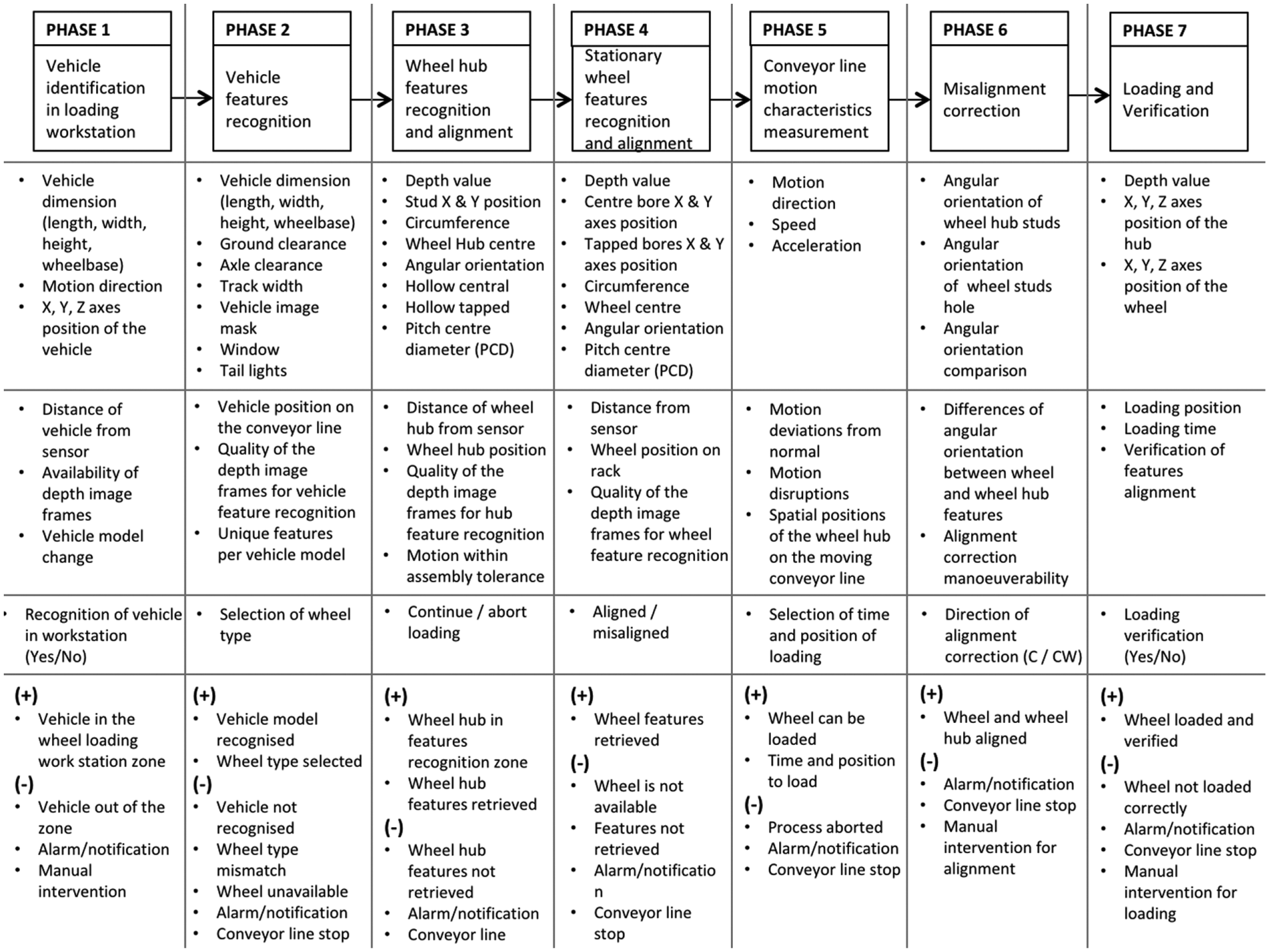
Wheel loading operation: seven phases of DSS process sequence.
Decision-making flow
In any phase of the operation, a decision is made based on an identified set of factors computed from the data captured from the shopfloor in that phase. A positive output from a phase implies that the operation has successfully completed up to that phase and will proceed to the next phase, whereas negative output indicates that there are deviations from normal beyond tolerable levels in that phase.
In phase 1, a decision is made on whether the vehicle has arrived at the wheel loading workstation or not. Some key factors to be considered here are distance of the vehicle from the depth sensor and vehicle body position on the conveyor line. In phase 2, the vehicle features are recognised such as wheelbase, height and width, and the vehicle model is identified. The wheel type corresponding to the identified model is chosen. In phase 3, the alignment features of the wheel hub on the moving vehicle body are identified. In phase 4, the alignment features on the stationary wheel are identified and compared to those of the wheel hub and a decision is made on whether a misalignment correction is needed or not. Across all the pre-loading phases 1– 4, the motion characteristics of the vehicle body on the moving conveyor line such as motion direction, speed and out-of-plane deviations are measured by the depth imaging sensors and in phase 5 are closely monitored to precisely determine when and where to load the wheels on the moving hub. In phase 6, if a misalignment correction is required, a decision is made on the most optimum manoeuvre the wheel-loading robot must make to the wheel to implement that correction. In phase 7, the wheel is actually loaded based on the control commands generated by the DSS in the pre-loading phases. After the loading is performed, a final verification of successful loading is made in order to begin the next cycle.
Data input
The DSS relies on the data provided to it from the assembly shopfloor. Two sets of assembly data are captured. The first set of data is offline, comprising of angular dimension of the bores that act as alignment features on the wheel to be loaded. The wheel is stationary before being picked up for loading, as it would be in the actual operation. The set up for capturing this data and the outcome of alignment feature identification outcome is shown in Figure 5.
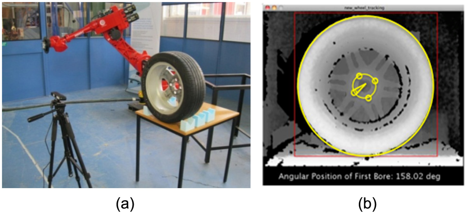
(a) Experiment setup and (b) depth image of wheel with features (bores) detected.
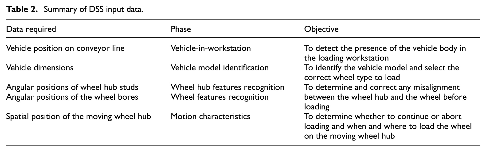
The second set of data comes from depth imaging sensors installed along the shopfloor of the moving assembly line. In this work, the wheel loading operation was simulated in laboratory conditions in which two sensors were used for dynamic measurement of far- and near-range motion characteristics of the moving conveyor line. The far-range sensor tracks the centre point of the wheel hub on the moving vehicle body to track its continuous three-dimensional (3D) position, speed and motion deviations along all three axes. The near-range sensor measures the angular positions of the studs, which are the alignment features on the moving wheel hub. Figure 6 shows the operation setup and Figure 7 shows the outcome of alignment feature recognition and measurement of wheel hub motion characteristics for a sinusoidal up-down simulated deviation. The complete details of the experiment are reported in Prabhu et al. 23 and summary of data used by the DSS for the wheel loading operation is summarised in Table 2.
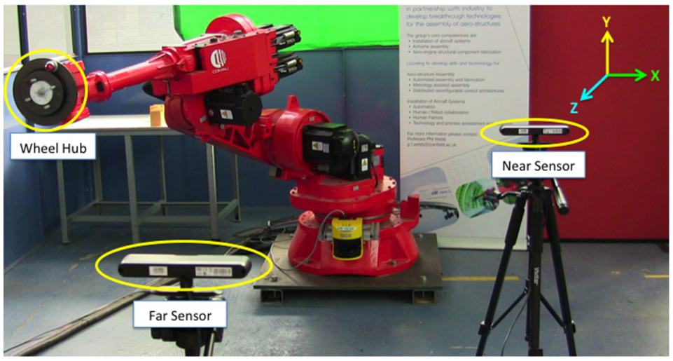
Wheel hub tracking set up.
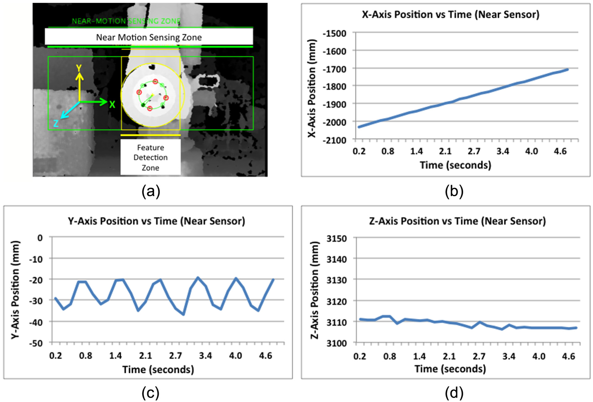
(a) Alignment feature recognition and motion characteristics (spatial position vs time) of the moving wheel hub in (b) X-axis, (c) Y-axis and (d) Z-axis.
Summary of DSS input data.
DSS tool development
A tool is needed as a platform to implement and test the DSS framework. The architecture proposed for this tool is shown in Figure 8. It comprises six modules, namely, the decision-making module, database module, data management module, rules repository module, user interface module and control interface module. The data captured by the shopfloor sensors are processed by the capture software and stored into the database. The data management module feeds the right data to the right component of the decision-making module at the right time, that is, according to the different phases of the wheel loading operation.
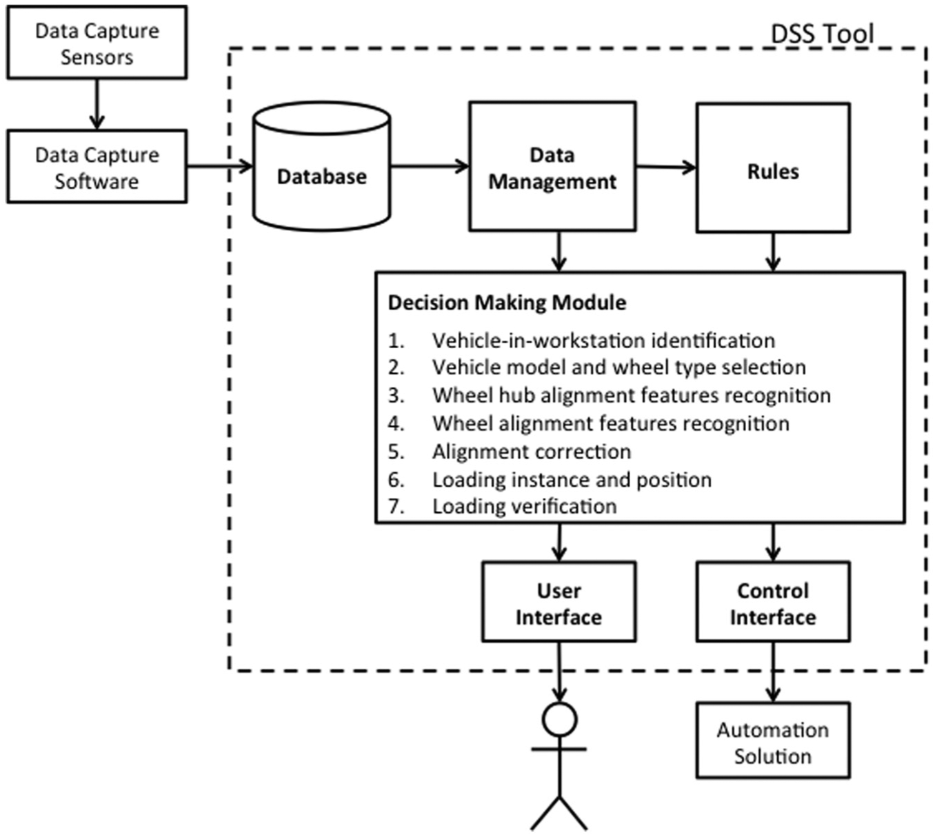
DSS tool architecture. 26
The decision-making module computes the necessary factors from the input data to evaluate the current state of the operation. This current state is then compared to the target state for each phase of the wheel loading operation and a decision is made in accordance with the relevant rules stored in the system for that phase. These decisions are sent to the automation solution through the control interface module and also to the user for visualisation and monitoring through the user interface module.
Expert rules
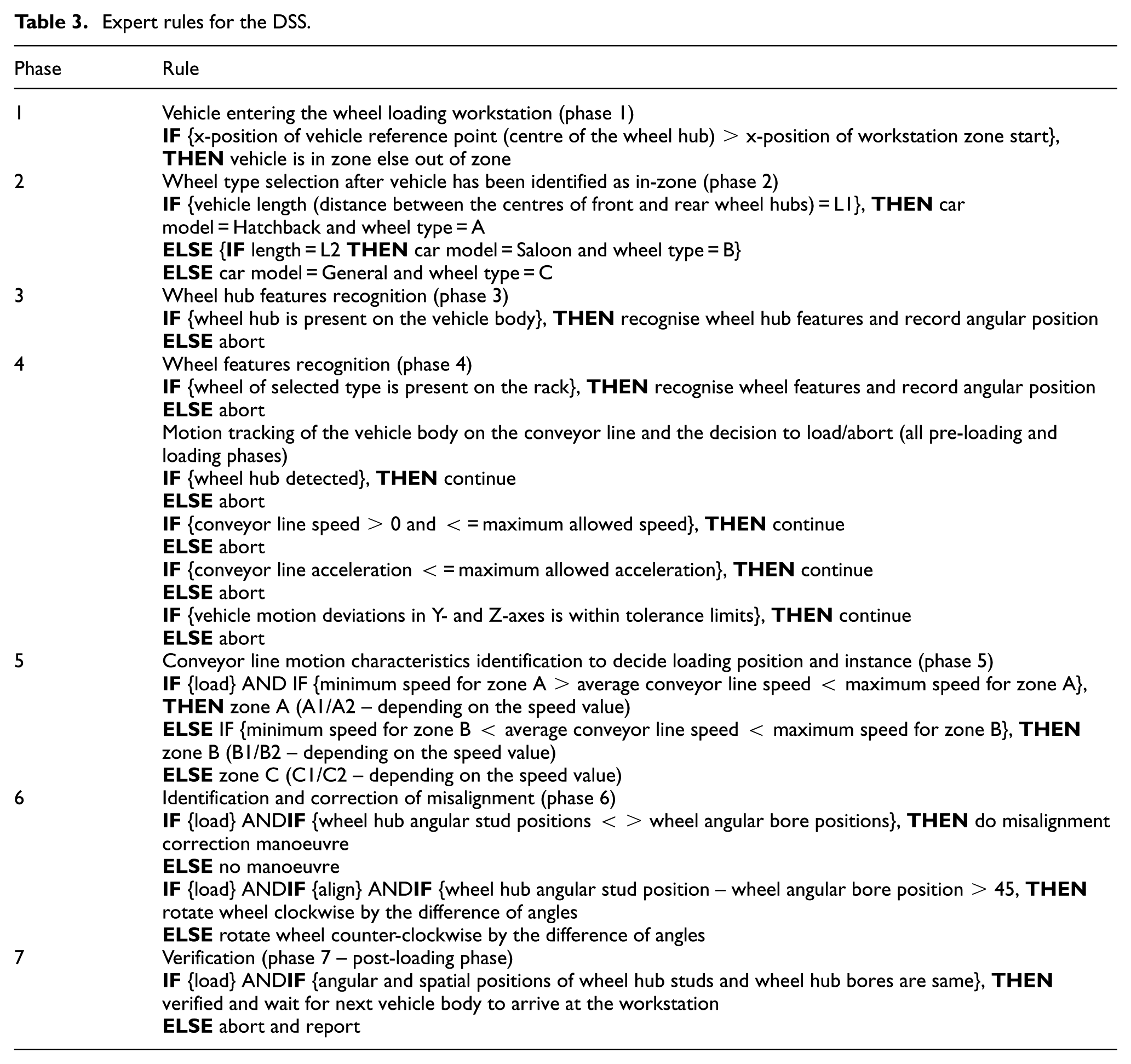
The decision-making module uses the expert rules stored in the tool repository to make decisions. These rules (Table 3) are based on the inputs of a wheel-loading technician working in an actual automotive production line. The relevant rule is picked based on the phase in which the wheel loading operation is in.
Expert rules for the DSS.
Results
Based on the above architecture, the DSS tool is developed in Microsoft Excel using the spreadsheet as user interface and macros for data processing and rule-based decision-making. The version of the tool reported here is offline, which means that the data collected from the wheel loading operation are stored in a database and the database is then taken as a one-time input by the tool. Therefore, the decisions made are not in real-time.
DSS tool
The DSS tool, a snapshot of which is shown in Figure 9 is divided into three functional sections: a section to display the input data captured from the shopfloor by the depth sensors (area A), a section to display the decisions made by the tool based on the input data (area B) and the middle section that represents the wheel loading workstation and its different zones (areas C to F). A symbol of the vehicle body and its movement along the workstation zones can also be visualised.
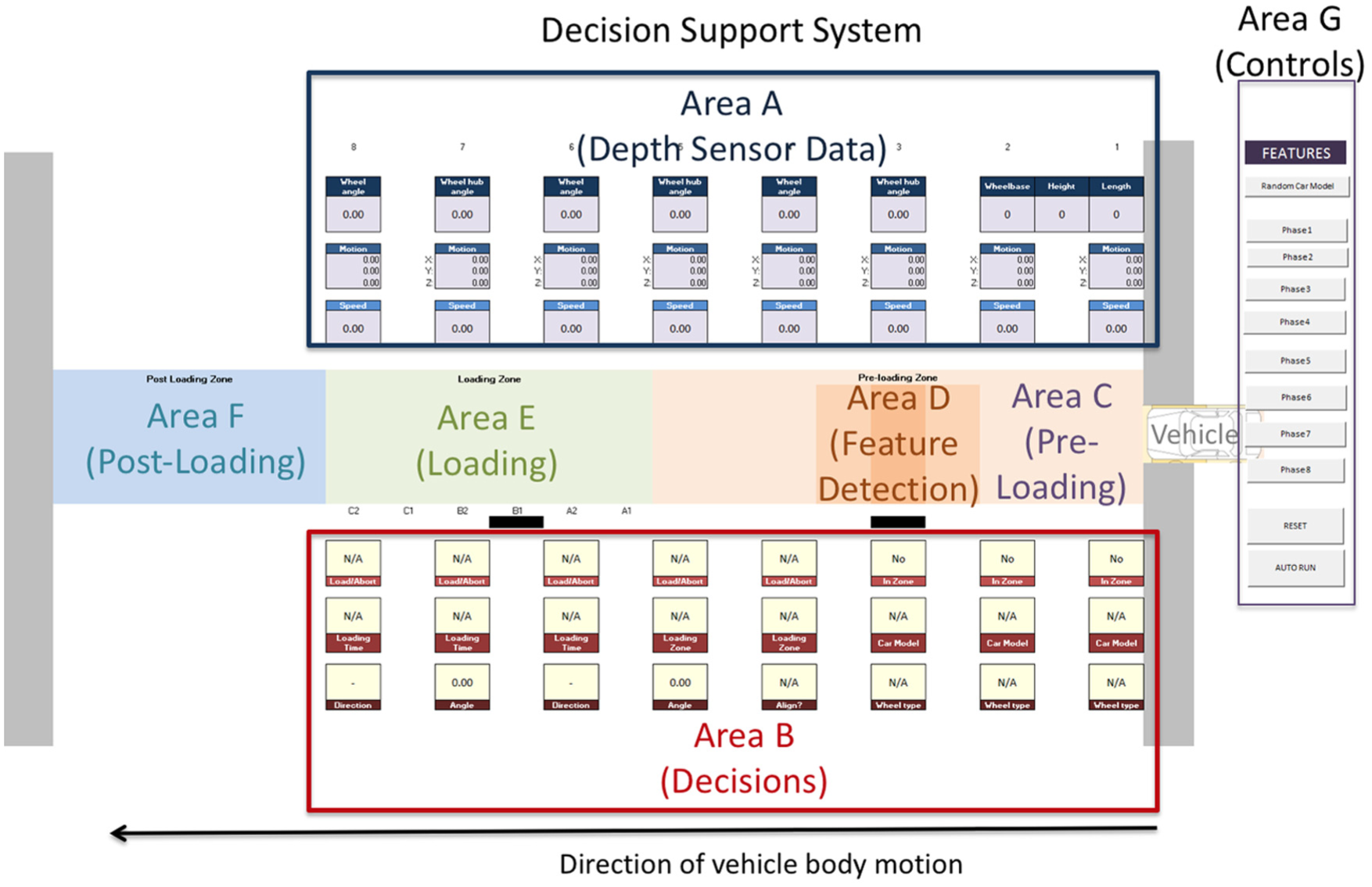
Snapshot of DSS tool.
The tool maps the entire seven-phase wheel loading operation into three zones: pre-loading (area C), loading (area E) and post-loading zones (area F) according to how it is segregated in an actual workstation. The DSS tool can be run to generate decisions for the whole loading operation at once or can be stepped from one phase to the next using controls shown in area G. The tool can also be reset to start the operation all over again.
In the pre-loading zone (area C), motion sensing of the moving hub is performed. Data from the depth sensor that tracks the conveyor motion and measures the motion characteristics are used to make decisions pertaining to the pre-loading phases 1–5. A specific area within the pre-loading zone is also demarcated as the feature detection zone (area D). In this zone, the alignment features of the moving wheel hub on the vehicle body and the wheel are recognised for making misalignment-correction decisions.
The loading zone (area E) is further divided into six sub-zones. The wheel could be loaded in any of these zones based on the speed of the moving vehicle body measured in the pre-loading phases. The post-loading zone (area F) is where the loading is verified and the outcome of the operation is reported.
Phase-wise implementation of the DSS tool
The seven phases of the wheel loading operation are implemented in the DSS tool. In each phase, decisions corresponding to the operation in that phase are made on the basis of input data and computed factors of that phase and the previous phases.
Phase 1 – vehicle detection
The wheel loading operation starts with identification of the vehicle body arriving in the wheel loading workstation. As soon as the depth sensors identify the vehicle body, the DSS tool changes the ‘IN-ZONE’ field from ‘No’ to ‘Yes’ (Figure 10(a)).
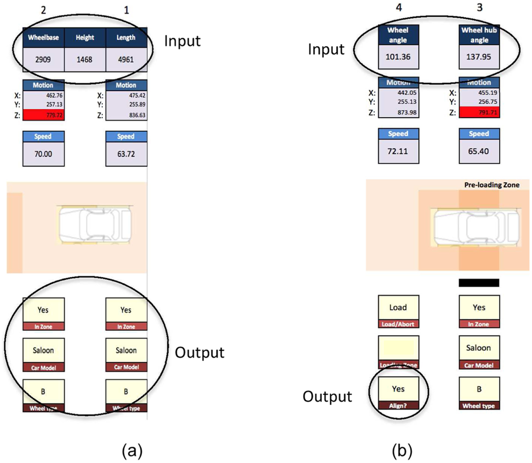
DSS results for (a) phases 1 and 2 and (b) phases 3 and 4.
Phase 2 – Vehicle model identification
After the vehicle is detected in the workstation, the sensors now measure the key dimensions of the vehicle in order to determine its model such as the wheelbase, height and length. Using this data, the vehicle model is identified and its corresponding wheel type is selected. In the example of Figure 10(a), based on the input data, the tool has chosen the vehicle model as ‘Saloon’ and the wheel type as ‘B’.
Phase 3 – wheel hub features recognition
The angular position of the studs on the moving wheel hub is entered into the DSS. This position is represented by a single degree – the angle of the stud that lies in the 90°–180° quadrant of the wheel hub. In the example of Figure 10(a), the wheel hub stud angle is captured as 137.95°.
Phase 4 – wheel features recognition
The angular position of the bores on the stationary wheel is collected by the DSS. In the example of Figure 10(b), the wheel bore angle is captured as 101.36°. At this stage, the wheel bore and wheel hub stud angles are compared and the decision of whether to correct the alignment or not is made. In this example, due to the difference between the two angles, the tool makes a decision to ‘Align’.
The X-, Y-, Z-position of the moving wheel hub as well as its speed of motion is captured and displayed in all the pre-loading phases 1–5 to detect deviations and disruptions that could significantly affect the loading operation. This helps the DSS to make load/abort decisions depending on whether the motion characteristics are within tolerances or not. Any positional figures outside of the expected range are flagged in red. In Figure 10(b), the DSS has made a ‘Load’ decision based on the motion characteristics observed in pre-loading phases 3 and 4.
The tool can also detect conditions when disruption has occurred such as the vehicle position exceeds the tolerance values and a decision to abort the process is made. The loading zone is indicated in red to notify the abort decision and the same is sent to the control interface to stop the conveyor line. Another possible condition that could occur is when there is a sudden decrease or increase in the conveyor speed. The tool will display the unexpected value, make a decision to abort the process and stop the conveyor line, illustrated in Figure 11.
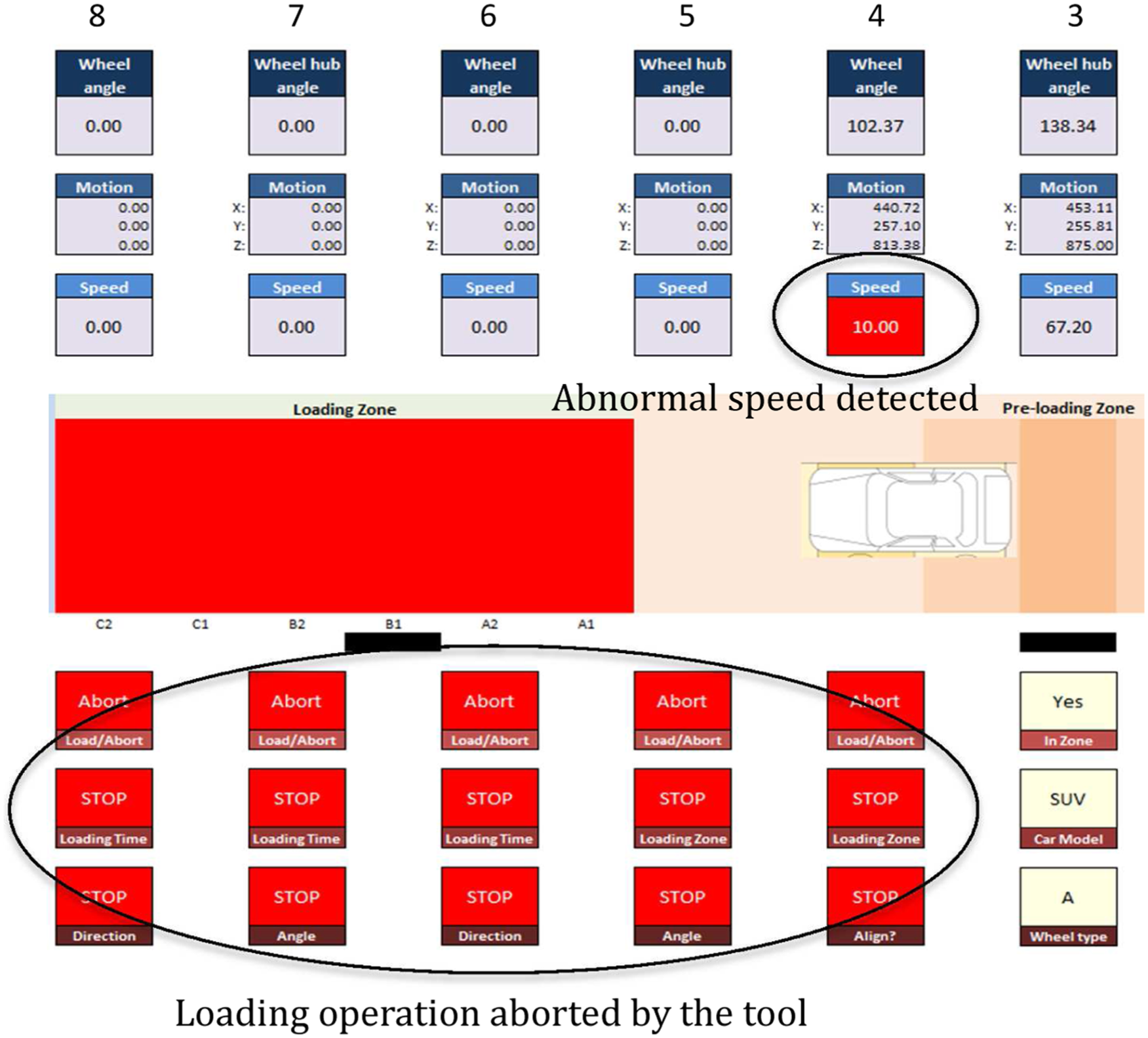
Loading process aborted due to the lower than expected speed in phase 4.
Phase 5 – loading zone identification
The loading zone is divided into six sub-zones. These sub-zones define when and where the loading step is to be carried out. Although the decision of which sub-zone to load the wheel in is made during the pre-loading phase, during the loading zone, the motion characteristics are closely monitored to provide the wheel-loading robot with accurate loading time and position commands. Figure 12(a) shows the tool has selected loading sub-zone B1, whereas in Figure 12(b), the tool has selected sub-zone A2, in two separate instances based on the speed of the moving vehicle body.
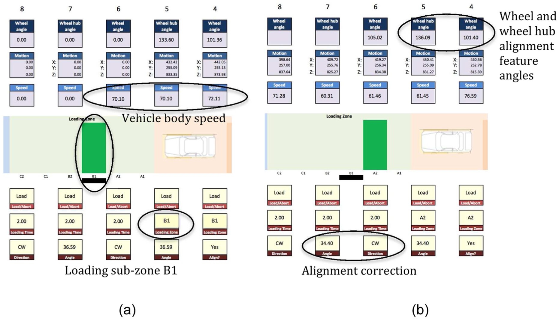
DSS results for (a) phase 5 and (b) phase 6.
Phase 6 – alignment correction
In this phase, the DSS compares the angular positions of the alignment features of the wheel and the wheel hub and computes the degree of misalignment. If the misalignment is outside the tolerable limit, the tool also determines the direction that the wheel must be rotated with respect to the wheel hub (clockwise or counter-clockwise) to correct the misalignment with minimum manoeuver. In the example of Figure 12(b), the tool recommends a ‘clockwise’ rotation of the wheel with a correction angle of 34.40°.
Phase 7 – loading and verification
In this phase, the robot performs the actual loading step by installing the wheel on the wheel hub of the moving vehicle body. This installation could occur in any of these two phases depending on the loading sub-zone selected. The conveyor line motion continues to be closely tracked by a depth sensor positioned within the loading zone and data from this sensor are used by the tool to make any last minute adjustments in loading position and time or make abort decisions.
The loading phase is very critical to the success of the wheel loading operation and therefore a second set of operational data that is available in real-time from the actual automation solution can be used in order to validate the decisions made by the proposed DSS. These data include conveyor tracking data from the conveyor motion encoders that indicate the position of the vehicle body on the assembly line (to verify the wheel hub position provided by the ‘Near’ Kinect sensor) as well as the robot arm tracking data from the robot motion encoders available via the control interface (to verify the ‘where’ and ‘when’ decision made by the proposed DSS). Any differences in the dataset provided to the DSS and the one available from the automation solution could raise a flag and in-turn be used by the DSS to issue an ‘Abort’ signal to the wheel loading operation.
The vehicle body enters the post-loading zone after the wheel is loaded. In this zone, the depth sensors capture the spatial positions of the wheel with respect to the vehicle body and feed this data to the DSS tool. The tool then verifies that the wheel has been successfully loaded by comparing these positions with the positions of the wheel hub (Figure 13). The tool at this stage resets itself and waits for the next vehicle body to arrive at the workstation.
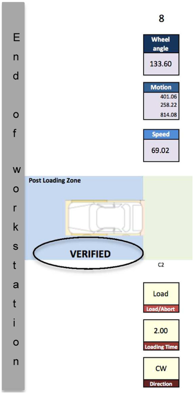
DSS tools verifies successful loading.
Discussion
In order to automate moving assembly operations, such as automotive wheel loading, the combination of superior dexterity, human-like observation of operational situations and human-like, adaptive decision-making is highly desirable. While the dexterity and precision can be attained with industrial robots and observation of operational situations can be obtained using commercially available sensors on the shopfloor, human-like decision-making systems are not available. Therefore, this article attempts to develop a unique DSS to make shopfloor decisions based on a human decision-making structure and process using live shopfloor data captured by low-cost depth imaging sensors.
Rasmussen explains the human cognitive decision-making process in his decision ladder concept. This concept is borrowed by this work to construct a framework for developing a DSS. The framework outlines the key activities, tools, factors, inputs and output of a DSS, devised specifically for a moving assembly operation such as the wheel loading operation on a moving vehicle body. The architecture of the DSS is designed and a spreadsheet-based DSS tool is developed. This tool takes in shopfloor data and using rule-based logic analyses, the current state of the operation vis-à-vis the expected/target state to control the operation. The rules are designed based on the heuristic knowledge involved in the moving assembly operation, which in this case is the automotive wheel loading operation.
The current DSS tool uses rules that are designed using the ‘If-Then’ logical construct. Such a construct is straightforward and facilitates the autonomous making of key moving assembly decisions by comparing the current and expected system states. While this construct is simple, robust and enables quick decision-making required for real-time efficacy, it is not self-learning. With every change in operational requirements, the rules stored within the DSS must be revised to be able to make better prediction of shopfloor states and therefore better decisions. Also, this construct cannot handle any situations that are unforeseen and will fail in such situations. This means that the tool requires comprehensive inputs and validation from the industry for all possible operational scenarios. Also, all the factors considered when designing the rules are assumed to have the same weight or influence on the operation. This may not be true for all operations and therefore, the factors will need to be weighed differently according to the specific application requirements. In the future, the tool would need self-learning ability to adapt itself to various operation scenarios and handle unforeseen problems using artificial intelligence-based techniques.
The two depth sensors, far and near, are used to perform macro- and micro-motion tracking of the moving wheel hub, respectively. While the far sensor is used to obtain the overall motion pattern, the near sensor is used to obtain precise spatial position of the wheel hub. The combination of motion pattern data and precise positional data helps the DSS make wheel loading (when, where and how) or abort decisions. Therefore, in this work, the far and near sensor data are not fused but used separately by the DSS. However, in situations where the demarcation of how the data could be used is not quite clear, data fusion techniques will need to be used in order to analyse/predict cumulative effects of multi-sensor data on the moving assembly operation.
The current version of the tool is an offline version, where the input data are not live from the sensors on the shopfloor. The data are pre-captured into a database, in this case an excel spreadsheet, and then processed and fed to the DSS tool. The tool simulates the real-time requirements across the operation using macros to include an assembly timeline and makes decisions based on the fed data in each of the different phases of the wheel loading operation. The data in the database come from actual experiments that mimic the moving assembly shopfloor and can be changed to subject the tool to different assembly scenarios.
The future work in this research will involve the development of an online DSS tool making real-time decisions based on live shopfloor data and also include other means of acquiring shopfloor data using alternative consumer-grade technologies, such as 3D wireless human motion capture systems and 3D object scanning devices. The wheel and wheel hub data provided by the Kinect sensors to the DSS were obtained from a physically simulated wheel loading workstation in which the wheel hub moved at an average speed of 100 mm/s with pre-defined deviation patterns for a distance of 2.5 m, mimicking the actual wheel loading conditions. The Kinect sensors (near and far) tracked the wheel hub, recognised the wheel hub alignment features and produced the motion data as well as the angular positions of the alignment features within a cumulative time of 4 s, considering that the total wheel loading time per wheel is 10 s in the industry. The maximum error margin of 2.78 mm in motion tracking and 1.46 mm in alignment feature position measurement are well within the industry standard tolerance of 4 mm (for the wheel and wheel hub type chosen). 23 The proposed DSS only takes this input data from the Kinect sensors and based on pre-defined expert rules, produces logical decisions in real-time for the different phases of the operation. Therefore, the proposed DSS is applicable in real-life vehicle assembly, but rigorous experimentation to establish validity on the actual assembly floor is required before industry adoption.
Conclusion
Moving assembly operations are complex and difficult to automate and therefore have remained largely manual in nature even in highly automated industries such as the automotive industry. However, such manual operations are costly, slow and have the potential to produce variable results. This work aims to meet this challenge by developing a unique DSS tool, driven by human cognitive decision-making process that can enable automation of moving assemblies. A framework to build the DSS tool is developed based on a decision-making structure and process proposed by Rasmussen in his seminal concept of the ‘decision ladder’. This framework provides a guide for the DSS tool to collect data from the shopfloor, determine the factors influencing the operation, apply expert rules to these factors and make autonomous decisions to successfully perform the operation. The proposed DSS uses assembly data captured by low-cost depth imaging sensors installed on the shopfloor.
The offline DSS tool uses pre-populated depth sensor data from a spreadsheet to compute the factors affecting the loading operation. Expert rules are applied on these factors during each phase of the operation to make decisions that apply to that phase. The DSS tool is able to make correct decisions for all known wheel-loading scenarios but would fail to do so for unknown scenarios because of the fixed ‘If-Then’ rule sets. The next phase of work is to develop the real-time version of the tool that could make decisions based on live depth sensor data and use rules with fuzzy logic enabling the DSS to handle unknown situations caused by ambiguous data.
Although DSS framework developed specifically for the wheel loading operation, it is generic enough to accommodate other moving assembly operations, such as engine assembly by amending data collection and expert rules to suit the end application. For this, the background data associated with the target application (such as component motion, orientation, dimensions and feature positions) and the expert rules comprising ‘If-Then’ constructs specific to the target application must be entered into the DSS. However, notwithstanding the generic nature of the framework, the current manifestation of the DSS as an excel spreadsheet may be limited in its applicability to other moving assembly operations.
Moving assembly operations are a significant part of most manufacturing industries and not limited to the automotive sector. Therefore this work, in combination with the growing research to creatively use low-cost gaming sensors to capture shopfloor data, has the potential to positively impact the efforts to automate such operations.
Footnotes
Acknowledgements
The authors would like to thank Global Robots Limited, UK, for its research support. Enquiries for access to the data referred to in this article should be directed to
Declaration of conflicting interests
The author(s) declared no potential conflicts of interest with respect to the research, authorship and/or publication of this article.
Funding
The author(s) disclosed receipt of the following financial support for the research, authorship, and/or publication of this article: This work was supported by the EPSRC Centre for Innovative Manufacturing in Intelligent Automation (Grant Number EP/I033467/1).