
Abstract
Edge stretchability refers to a sheet metal’s capability to resist edge cracking during edge forming and flanging. In this article, a quantitative method has been proposed to evaluate the effect of punching or trimming of sheet metals on the degradation of their edge stretchability. This method adopts the Marciniak and Kuczynski concept to quantify edge damages due to punching or trimming. A novel index, the effective failure strain ratio, is introduced. Effective failure strain ratio is strain-based, and it is defined as the ratio of the actual edge failure strain to the theoretical edge failure strain. The algorithm to calculate effective failure strain ratio based on hole-expansion simulations is detailed. The magnitude of effective failure strain ratio depends on the damage value, which corresponds to the edge damage caused by preprocessing such as punching. Numerical studies are conducted to demonstrate the applicability of this method. The results show that the degradation of edge stretchability of materials with higher hardening exponent (n-value in power hardening law) is more sensitive to edge damage. Hole-expansion experiments using two grades of dual-phase steels are conducted to validate the conclusions deduced from the simulations. The comparison between the experimental and numerical results shows that the proposed method is able to predict phenomena appearing in the experiments. The quantitative relationship between damage value and the punching clearance has not been established in this work yet, which requires extensive experimental investigation. However, a qualitative link has been clearly demonstrated, and this method provides a new perspective to express the pre-damage and its effect straightforwardly.
Introduction
More and more advanced high-strength steels (AHSSs) were employed in the automotive industry due to the increasing demand of energy saving and environment protection. 1 Although AHSS showed good combination of high strength and good formability, extensive efforts were devoted to solve stamping problems of AHSS during the application, such as springback, die wear and different fracture modes. For automotive component manufacturing, edge stretchability has become an important performance index in addition to traditional material properties. Edge cracking is a failure mode which usually appears in hole-expansion and stretch flanging. It is difficult to predict edge cracking with conventional numerical and theoretical methods, such as forming limit diagram (FLD) and ductile fracture criteria (DFC), because edge cracking of AHSS is influenced by the mechanical properties, material microstructures, processing parameters and edge quality due to punching history. 2
Hole-expansion tests are usually used to obtain edge stretchability of steel sheets. The procedure is to expand a pre-cut hole with a conical, spherical or flat punch till edge cracks appear. 3 Edge cracking usually happens on the hole edge along the radial direction. Several research groups have carried out systemic experiments and built models to predict edge cracking. Comstock et al. 4 discovered that higher strength made hole-expansion capability lower in ferritic stainless steels and austenitic stainless steels. Fang et al. 5 investigated the influence of tempering temperature on hole-expansion property of C–Mn steel. Konieczny and Henderson 6 carried out a series of punching and hole-expansion experiments to investigate the influence of hole edge quality on the hole-expansion ratios (HERs). The holes were prepared in four methods, which were piercing, reaming, laser cutting and punching. They found that HER after reaming was the highest, and there was no linear relationship between HER and clearances of punching. Yasuhiro and Yoshiaki 7 found that the fracture location during hole-expansion was influenced by a combination of hardening exponent n, anisotropy coefficient r and hole diameters. Xu et al. 8 found that the fracture direction was related to strain rate sensitivity, shape of the yield surface and damage-producing MnS stringers aligned along the rolling direction. Koebel et al. 9 discovered that the strain paths’ behavior of the points near the hole edge was nonlinear due to the shearing process. Hiramoto et al. 10 developed a new technology based on a maximum principal strain gradient to predict edge cracking. Anderson et al. 11 investigated the fracture during hole-expansion without edge damage using Gissmo failure criteria. Levy and Van Tyne 12 proposed a new index for production personnel to evaluate material performance during sheared edge stretching. Lee et al. 13 developed a new type of punch to improve the HERs of AHSS. Butcher et al. 14 found that surface roughness and void initiation due to the shearing process were not significant factors on the edge cracking of baron steel used in hot stamping applications. Cheng 15 developed a one-step hot stamping–forging method to increase the tensile strength of high-strength steel.
Finite element method (FEM) has been a powerful tool in investigating complex phenomena. Researchers have used FEM software packages to predict edge cracking with the help of the experimental results and various material models. Ductile fracture criterion (DFC) is a conventional method to predict failure, which is also used to simulate edge cracking. Sartkulvanich et al. 16 conducted hole-expansion simulations. They found that Rice–Tracey fracture criterion was suitable for the punching simulation. And the average damage value over the fracture zone could be used as a threshold parameter to predict subsequent edge cracking in hole-expansion experiments. The maximum principal stress, hydrostatic stress and equivalent stress are considered by Ko et al. 17 in their new DFC. They discovered that their criteria were better than the existing ones, such as Oyane and McClintock criterion. Kuwabara et al. 18 investigated the effect of anisotropic yield functions on the accuracy of hole-expansion simulations. They found that Yld2000-2d with an exponent of 4 provided good agreement with the experimental results. Chung et al. 19 investigated the poor hole-expansion performance of twinning-induced plasticity (TWIP) steel incorporating the hardening behavior with stiffness deterioration before macro-crack formation and softening behavior after macro-crack formation.
FLD is often employed to predict localized necking failure under proportional loadings. In consideration of deficiencies in predicting failure under non-proportional loading, it is usually applied with a safe margin. FLD was originally developed by Keeler and Backofen 20 by conducting extensive forming limit tests for many steel sheet metals. Their work resulted in die tryout shops to use it as a practical method to check potential splitting. Since it is time-consuming and expensive to obtain FLD data, several numerical and analysis methods were developed to predict FLD. One of the first theoretical models to predict formability of sheet metal was proposed by Hill, 21 which was applicable to the left-hand side of FLD with negative minor strains. Hill’s assumption of zero-extension was not able to predict the sheet necking in biaxial stretching. To overcome these drawbacks, Marciniak and Kuczynski (M–K) 22 presented a method that introduced an initial imperfect band into an infinite sheet metal in the form of thickness reduction as a mechanism to trigger the deformation instability. M–K model has been extended to analyze sheet metal necking by considering different aspects of forming processes. Many research groups have extended the M–K model to study the effects of material models. Yao and Cao 23 improved the accuracy of FLD prediction under nonlinear strain paths by evolving the center and curvature of the yield function using M–K analysis. Wu et al. 24 evaluated the predictive capability of the anisotropic yield criteria with the help of FLD obtained by M–K analysis. Safikhani et al. 25 introduced an internal length scale into conventional constitutive equations in conjunction with M–K approach to determine the forming limit stress and strain diagrams. He et al. 26 incorporated the extended through-thickness M–K analysis with Yoshida–Uemori two-surface kinematic hardening constitutive model to evaluate Bauschinger effect on the forming limit prediction under stretch-bending condition. The aforementioned efforts proved that the M–K approach continued to be a powerful method of modeling forming limit behavior. For a given imperfection factor or damage value, M–K approach allows the comparison of effects of various material models. Moreover, numerical integration of the material evolution inside and outside the band may be carried out without complex analytical derivations.
Fracture forming limit line (FFL) is also well developed to investigate failure in sheet metal forming. It is also characterized in the principal strain space. The concept of FFL proposed by Atkins 27 was not of interest to researchers and defined as a second curve parallel to the FLD. Due to the development of single-point incremental forming (SPIF), FFL gained interest in the past years. Cristino et al. 28 traced the strains and stresses of various positions over the surface of the hole-flanged in SPIF process and found that the strain loading ratios were constant for different material elements. From these data, the experimental values of accumulated damage at the sites of fracture are determined. Isik et al. 29 introduced the shear fracture forming limit line (SFFL) with the help of applying the theory of plasticity to proportional strain loading paths and developed a new experimental method to obtain the values at the onset of fracture. The graphical representation of FFL is not simply the extension of traditional FLD. Martins et al. 30 proposed an analytical framework to characterize loci under plane stress conditions. They combined the FFL with the physical failure mechanisms associated with excessive thinning and excessive in-plane and out-of-plain distortion. With the development of new processing, the theoretical and experimental research on the FFL is still going on.
As mentioned above, edge cracking is a common phenomenon during stamping of AHSS. However, this failure mode depends on edge quality. In practice, hole-expansion is usually chosen to investigate edge cracking because it is straightforward to observe the failure during the experiments and easy to measure the deformation. Notably, the stress state of the hole-expansion is in uni-axial tension. 31 Shi and Chen 31 suggested that HERs obtained from a conical punch hole-expansion tests could be used as the edge stretchability limit criterion, which could then be used in the numerical simulations to predict edge cracking in practical applications.
In this article, a quantitative method has been proposed to evaluate effects of punching or trimming of a sheet metal on the degradation of its edge stretchability. The authors have employed this method to evaluate the influence of initial hole diameters on the HER. 32 The method adopts the M–K concept to quantify edge damages from previous punching/trimming operations. An edge stretchability index, the effective failure strain ratio (EFSR), is introduced in this article. EFSR is defined as the ratio of the measured edge failure strain to the theoretical edge failure strain without damages from punching. The approach to calculate EFSR based on hole-expansion simulations is detailed. The magnitude of EFSR depends on the severity of damages expressed as the imperfection value in M–K model, which corresponds to the edge damage caused by preprocessing such as punching or trimming. Numerical studies with ABAQUS/Standard are conducted to demonstrate applicability of this new method. The results show that the degradation of edge stretchability of the materials with higher hardening exponent is more sensitive to the edge damage. Punching and hole-expansion experiments using two grades of dual-phase (DP) steels are conducted to validate the conclusions obtained from the simulations. The comparison between the experimental and numerical results shows that the proposed method is able to qualitatively predict some phenomena observed in the experiments. A qualitative link between damage value and punching clearance has been clearly demonstrated.
EFSR
In hole-expansion process, the stress state of the hole edge is the same as that in uni-axial tension. If the hole edge is in a perfect condition without any preexisting damages such as micro-cracks or surface roughness, edge cracking strain should be either the forming limit strain or the fracture limit strain under uni-axial tension, whichever is lower. For almost all sheet metals used in stamping, the forming limit strain is usually lower than the fracture limit strain when loaded in uni-axial tension. However, extensive test data showed that the actual edge cracking strains were always lower than the theoretical FLD strains, with values highly dependent on edge quality and material itself, as illustrated in Figure 1.
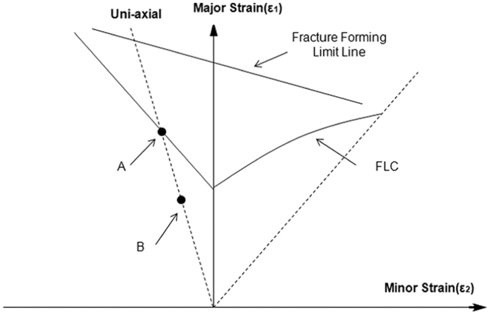
Illustration of comparison between theoretical edge cracking strain (Point A) and actual edge cracking strain (Point B) in classic FLD.
To quantitatively investigate the relationship between the theoretical and actual edge cracking strain, an evaluation index, the EFSR, is proposed in this section. The EFSR is defined as the ratio of the measured edge failure strain to the theoretical edge failure strain without preexisting damages. It is introduced for the purpose of understanding edge cracking strains in terms of different edge damage values and can be obtained from extensive hole-expansion simulations. The basic steps to obtain EFSR are illustrated in Figure 2 with explanation followed.
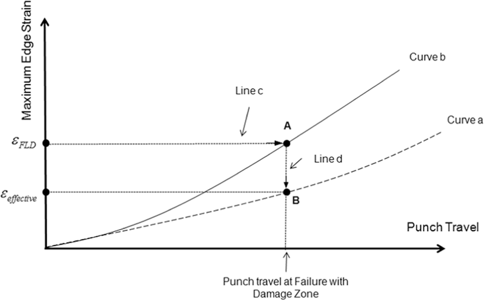
Schematic of edge strain evolution for a given damage value and material.
First, hole-expansion simulation is conducted. The material properties and geometry of the blank sheet are the same everywhere, that is, there is no damage on the blank sheet. The vertical axis in Figure 2 represents the maximum principal strain along the hole edge, that is, the maximum circumferential strain during hole-expansion. Curve a illustrates the evolution of maximum principal strain along the edge as the punch travels. Since the non-damaged assumption, the circumferential strain along the edge is the same everywhere.
Second, hole-expansion simulations with damage zones are conducted. The concept of M–K model is adopted to build these models. The damage based on M–K concept can be carried out by many methods, such as thickness reduction or material property differences. In this article, thickness reduction is used. A damage zone is prescribed with a slightly thinner strip. The purpose of the damage zone in this method is the same as that in the classic M–K method, which is to trigger the localized necking at the location preset. It is important to note that such a damage zone is not physically present. Rather, its introduction in a numerical model is to investigate the degradation of the failure strain from such damage as compared to non-damaged material. This is essential to the understanding of this approach, and it is in accordance with the original M–K concept.
Due to the round shape of the steel sheet in numerical model, the shape of damage zone is set as sector. The thickness of the initial material is
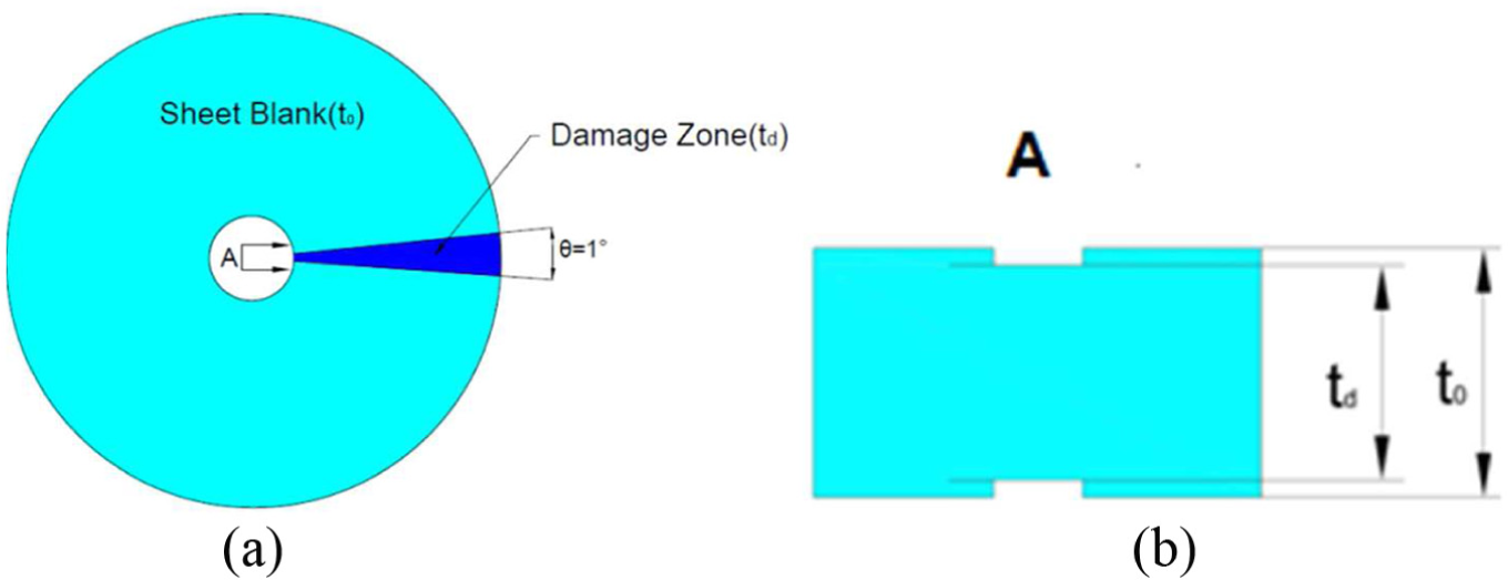
Schematic of preexist damage zone in (a) round specimen and (b) cross-sectional view of A.
Although the real damage on the hole edge during hole-expansion locates on the cylindrical surface which consists of thickness direction and circumference direction, the fracture appeared at the edge of hole, which is the same as the assumption above. It is equivalent between the damage experienced from previous punching operations and the thickness imperfection assumption, although the quantitative relationship needs calibration.
With the employment of the M–K concept, Curve b in Figure 2 illustrates the evolution of the maximum circumferential strain in damage zone along the edge. They can be calculated from the numerical simulations. Since there is a preset damage zone, the strain at the edge inside the damage zone will rise more quickly than the strains of perfect edge.
As mentioned above, the stress state of the hole edge during hole-expansion is the same as that in uni-axial tensile tests. Furthermore, for deformation of steel sheet blank, the material will achieve fracture rapidly after localized necking appears. To save time and computing resource, localized necking strain is taken as the failure criterion. Obviously, the strain state of the material at edge corresponds to the uni-axial condition on the left-hand side of FLD. Hill 21 has proposed a well-established theoretical model to predict forming ability, as reviewed briefly in the following.
For a wide specimen, the strain in width,
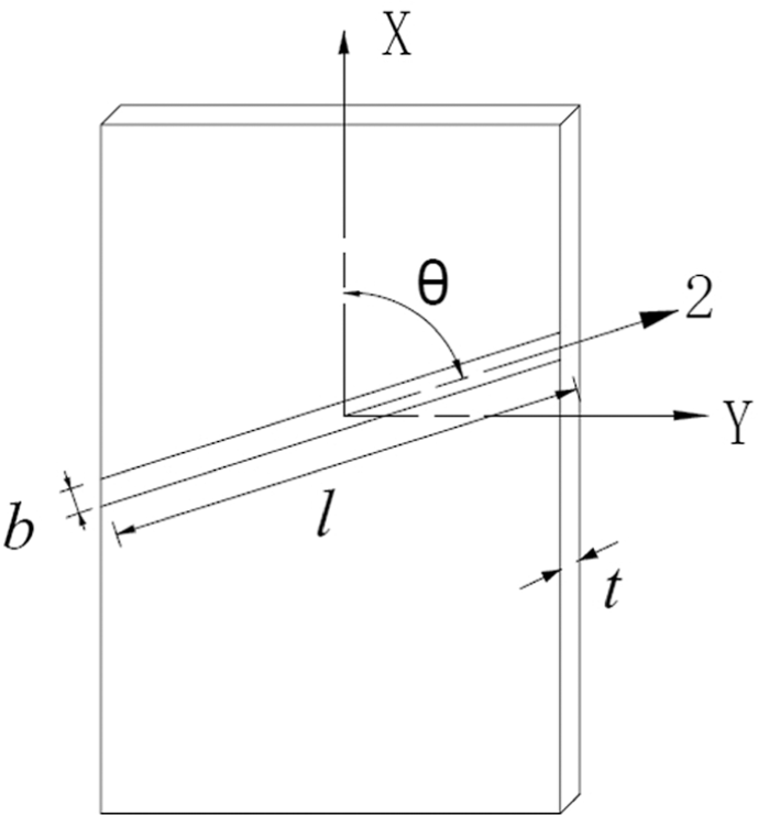
Localized necking band in wide specimen.
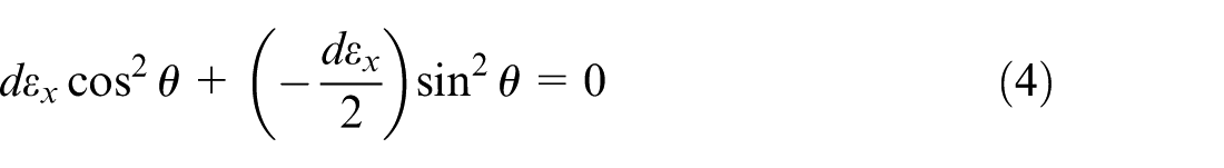
The characteristic angle,

For uni-axial tension in the X-direction, the flow rules for the isotropic material predict that
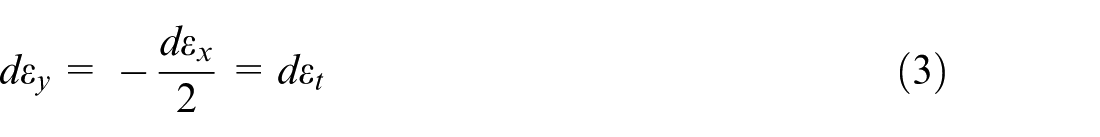
Substituting equation (3) into equation (2)

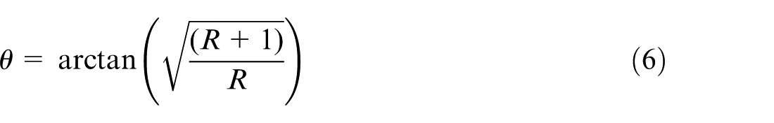
Additionally, if the metal is anisotropic,
The cross-sectional area of the necking,
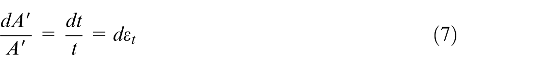
The area perpendicular to the X-axis is
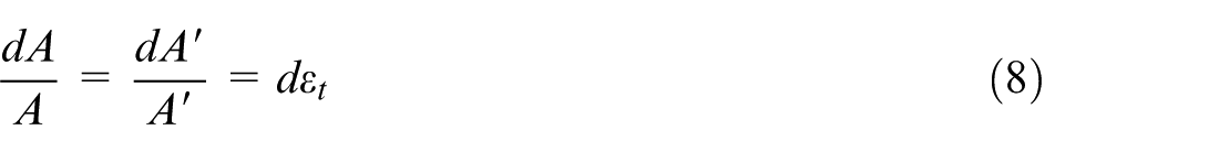
The localized necking can form only if the load, F, can fall under the constraint,

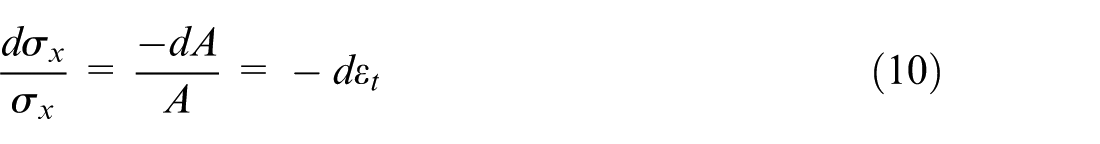
With
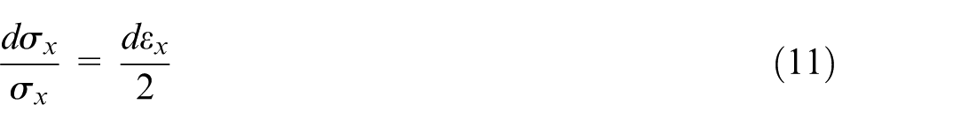
For a material obeying power law,

In other words, the theoretical edge cracking strain for the isotropic materials in Figure 1 corresponds to major strain of 2n and minor strain of
Third, the punch travel at which the maximum major strain of the edge inside damage zone reaches 2n can be determined from Curve b with the help of Line c in Figure 2, which is the horizontal coordinate of Point A. Furthermore, the maximum edge strain without damage at the same punch travel at point A can be obtained with the help of Line d, which is the vertical coordinate of Point B in Figure 2. The strain determined by point B is defined as the effective failure strain in this method.
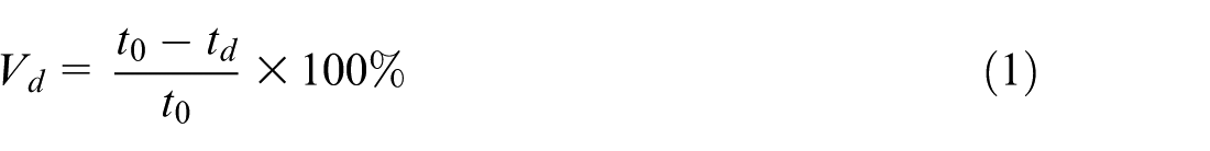
Finally, the EFSR is calculated using equation (13)
Case study
Material property and influence factor selection
DP780 and DP980 with the initial thickness of 1.4 mm were chosen to conduct the hole-expansion simulations based on the method outlined in the section above. DP steels consist of a ferritic matrix containing a hard martensitic second phase with various volume fractions. The strength of the steel becomes higher with increasing volume fractions of hard second phases. There is also no complicated phase transformation during forming like transformation-induced plasticity (TRIP) steels. So the selected materials are suitable to investigate the influence of the mechanical properties on the EFSR and the degradation of edge stretchability due to edge damage. Hardening exponent n is chosen to be investigated, because it is an important parameter, which signifies the work hardening characteristic of a material. The higher the value of n, the higher the rate at which the material work hardens. It is also an indicator of material stretch formability, because n is equal to the limit strain for uniform deformation theoretically.
The mechanical properties of both DP780 and DP980 are obtained from the material samples produced by Baosteel Group Corporation. According to the Chinese test standard GB/T 228.1-2010,
33
uni-axial tensile tests were carried out on a ZWick BTC-T1-FR020TN A50 tensile testing machine at room temperature to obtain the true stress–true strain data. In order to provide repeatable experiment results, at least four replicates were performed for each material. Only the specimens with cracking locating within the gauge length were measured. As discussed above, power law hardening model,
The fitting results of two grades of steel for power law model.
Since the difference between the experimental and theoretical edge strains is tiny, and the effect of hardening exponent is to be investigated, 2n is considered as the failure criterion in the simulations.
Simulation modeling
The hole-expansion simulations were conducted with ABAQUS/Standard. The damage zone on the blank is 1° of sector as shown in Figure 3(a). As mentioned above, the thickness of damage zone was set less than the adjacent part, the perfect zone. The punch of hole-expansion was conical one with 60° taper. The punch moved at a constant velocity of 36 mm/s. To save the calculating time, shell elements with reduced integration (S4R) were used. The numbers of integration points along the thickness direction were set as 5. Tools, such as die, punch and blank holder, were set as rigid bodies. The shape and relative position of the parts in the model are illustrated in Figure 5(a). Coulomb friction model was used, with friction coefficients between tools and blank set as 0.15. Von Mises yield criterion was used in these models. Isotropic hardening was assumed. Since the strain gradient in damage zone was much larger than that in perfect zone during forming, finer elements were divided in the damage zone. The elements’ density of the damage zone in the blank was at least 10 times of the perfect zone. Figure 5(b) shows the elements’ density difference. Additionally, the output frequency was set at every 0.001 unit of loading time, that is, 0.0005 s in order to get sufficient data to plot the history of the max circumferential strains in the damage zone with required accuracy.
Illustration of (a) the basic simulation model and (b) elements’ mesh in damage zone.
Results of simulation
The range of the damage value was set 0%–10% of the thickness, that is, the range of the damage zone thickness was set in 1.4–1.26 mm. The maximum circumferential strain histories were output at an interval of every 1% of the decreasing thickness. Since the time intervals of every output step were short enough, the histories of maximum circumferential strains of the edge with and without damage zones could be recorded and output with enough accuracy. The results of the simulation of the selected materials are plotted in Figure 6.
Histories of maximum edge strains for different materials: (a) DP780 and (b) DP980.
As shown in Figure 6, for the selected materials, the curves standing for evolution of maximum circumferential strain of the edge without damage are both the most gentle ones. The larger the damage values, the faster the maximum edge strains increase. When the damage value is large, that is, the edge quality is bad, the maximum edge strain will reach the theoretical cracking strain at small punch travel, which means that edge failure occurs early. Furthermore, according to the steps explained in section “EFSR,” the corresponding edge strain without damage at the same punch travel, B0, C0, D0, E0 and F0 can be obtained with the help of points B, C, D, E and F in Figure 6(a) and (b). The strains indicated by points B0, C0, D0, E0 and F0 are the parameter
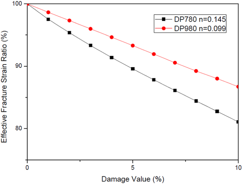
Relationship between the EFSR and damage value of selected materials.
With the expression of EFSR in terms of damage value, that is, conversion from Figure 6 into Figure 7, the behavior differences between these two materials can be shown much more clearly. For DP780 and DP980, EFSR is monotonically decreasing with the increasing of damage value. However, EFSR of DP780 with larger n value decreases more rapidly than that of DP980. This phenomenon can be understood in terms of the sensitivity of edge stretchability. Edge stretchability of the material with higher n value deteriorates faster than that with lower n value. The higher the n, the more sensitive edge stretchability of the material is to the edge damage. Although the edge stretchability of DP780 is better than that of DP980 when the edge quality is good, it is possible that DP780 exhibits worse edge stretchability than DP980 even it suffers the same level of damage as DP980 as long as the damage level is bad enough.
Experimental verification
Experiment preparation
To validate the applicability of the EFSR index proposed in this article, hole-expansion tests were designed. The specimens for hole-expansion were prepared as round ones with a hole in the center, as shown in Figure 8(a).
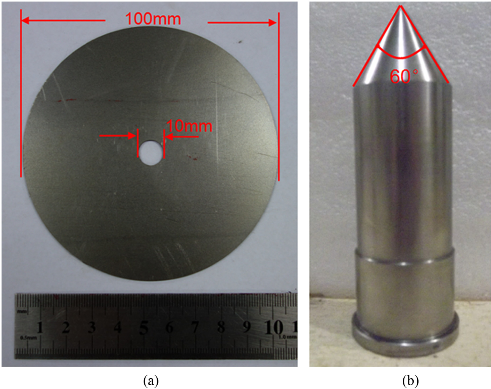
(a) Specimen and (b) punch for hole-expansion with dimensions demonstrated.
The holes on the specimens of both DP780 and DP980 were prepared in two methods. The first method was punching. The outer diameter of the punch was 10 mm. The inner diameters of the dies were 10.18, 10.25 and 10.36 mm. The thickness of the sheet blank was 1.4 mm, coincident with what was set in the simulations. So the corresponding punching clearance values were 6.43%, 8.93% and 12.86%, respectively. A batch of six specimens were fabricated in the same condition for three applied punching clearance values. Both materials were prepared in the same dies and clearances to make sure that the damage values on the hole edges were the same. The second method was wire cutting with electrical discharge machining (WEDM). The damage values on the hole edge prepared by WEDM were much smaller than those prepared by punching and would provide clear contrast in terms of damage levels.
The hole-expansion experiments were performed on a hydraulic press with a 60° conical punch after preparing holes. The hole-expansion punch with dimension demonstrated is shown in Figure 8(b). The die was hollow and a camera was mounted inside to record the punch movement in real time. When the first crack through the thickness appeared, the punch movement stopped.
Results of experiments and comparison with simulations
One of the cracked specimens is shown in Figure 9. The inner diameters of the cracked holes were measured and averaged. The HERs were calculated by equation (14)
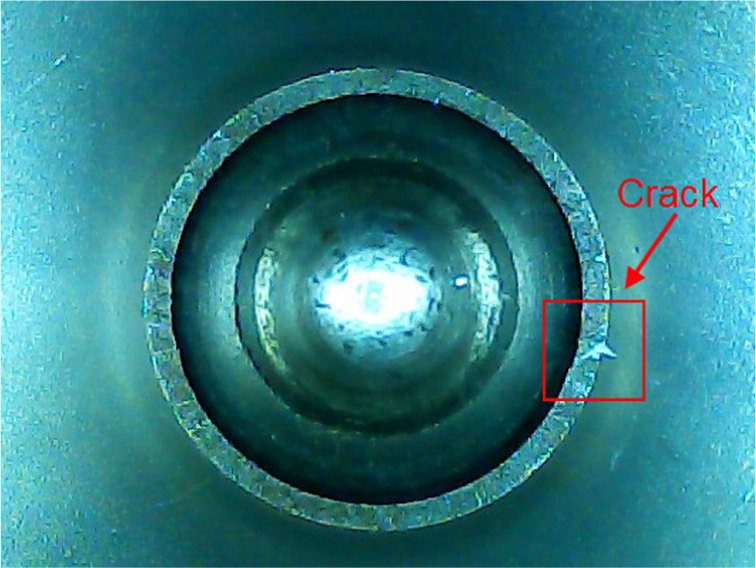
One cracked specimen.
The results of the hole-expansion experiments of the selected materials under different punching clearances are shown in Figure 10(a). HER of holes produced by WEDM are also illustrated. Figure 10(b) illustrates the relationship between the HERs and the damage values with the help of the simulation results in Figure 7. The HERs of holes produced by WEDM were taken as the HERs of holes without damage for simplicity, that is, 63.86% for DP780 and 59.03% for DP980. Then HERs of holes under different damage values in the range of 1%–10% for both materials could be obtained with the help of EFSR values in Figure 7. The method to obtain the HERs under given damage value in this study is shown in equation (15)

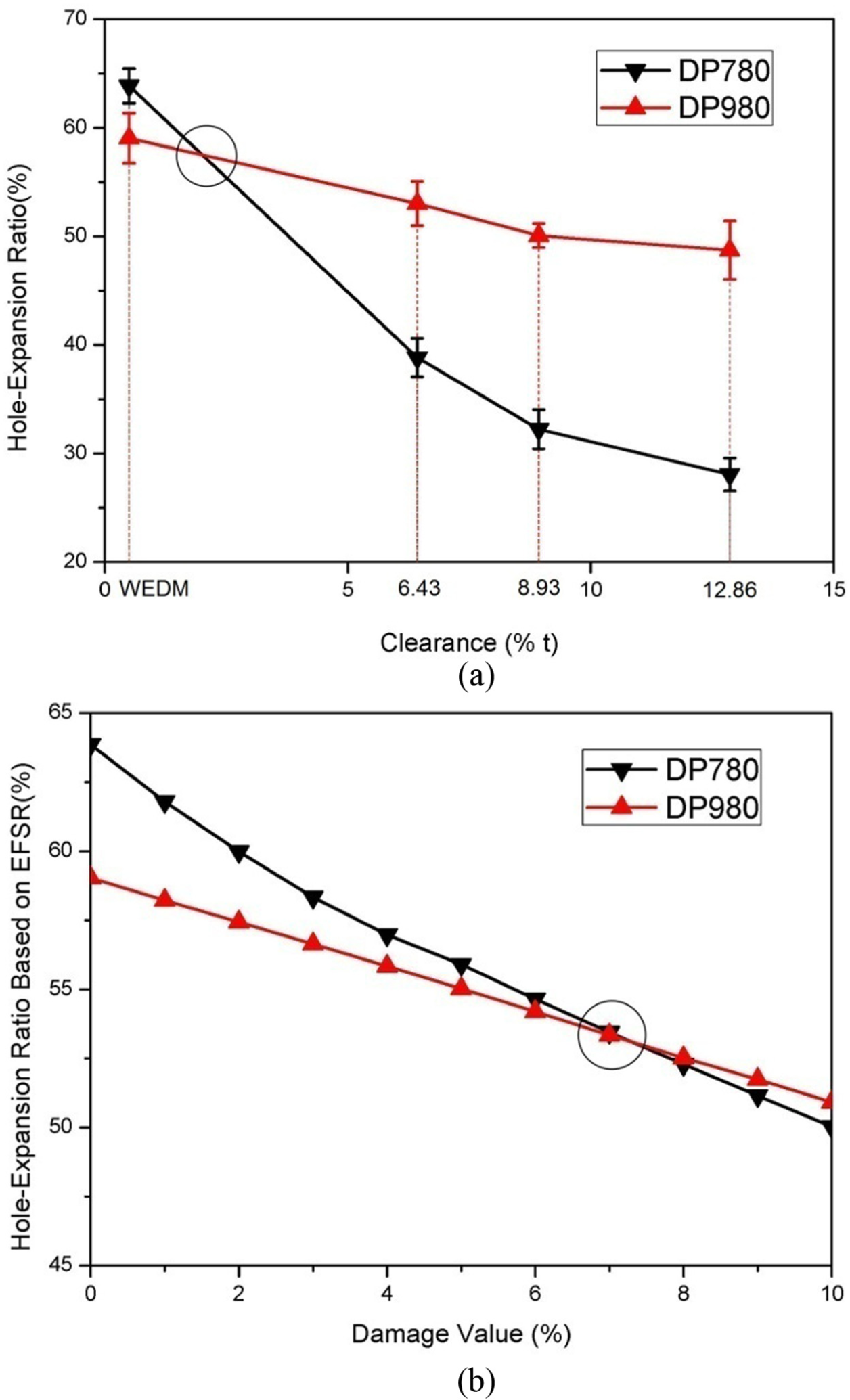
(a) HER under different punching clearances in experiments and (b) HER based on EFSR under different damage values.
Two main predictions from the simulations and EFSR can be validated by comparing Figure 10(a) with Figure 10(b).
The trend lines of the HER obtained based on EFSRs from the simulations with the edge quality deteriorating in certain range are the same as those from the experiments. In Figure 10(a), it is clearly shown that the HER of DP780 is higher than that of DP980 if the central holes are produced by WEDM, that is, prepared with less damage on the edge. However, in the range of punching clearances preset, HERs of DP980 are higher than those of DP780. Although both of them are decreasing with the increasing of punching clearance, HERs of DP980 are decreasing slower. As shown in Figure 10(b), HERs of DP780 decrease more rapidly than those of DP980, because the sensitivity of degradation of edge stretchability of materials with higher n values is higher than that of the materials with lower n values.
An intersection is observed on the trend lines standing for DP780 and DP980 in Figure 10(a) and (b).The intersection locates in the horizon coordinate range between WEDM and 6.43% of punching clearance in Figure 10(a). And in Figure 10(b) its horizon coordinate locates near 7% damage value. This intersection means that edge stretchability of DP780 will fall worse than that of DP980 under certain damage value or under certain punching clearance, although it is better than that of DP980 when the edge quality is perfect.
Discussion
This method is based on the concept of M–K model. In Figure 2, Curve a and Curve b stand for the strain evolution at the same location. The difference is whether there is damage zone on the sheet blank. When the maximum edge strain at the edge with damage gets to FLD strain, 2n, localization will start to develop. At the same punch travel, the maximum edge strain of the perfect edge only gets to
The comparison between the experimental and numerical results shows that the approach developed in this article can give an appropriate explanation and prediction on phenomena appearing in the experiments. The method clearly demonstrates that the edge stretchability of a given material is influenced by both edge damage levels and material properties in a nonlinear form. But it should be noted that a quantitative link between the punch clearance and the damage value has not been established in this study. That is why Figure 10(a) and (b) cannot be integrated and compared in one figure. Such an effort is not trivial and requires extensive experimental investigation. However, a qualitative link has been clearly demonstrated.
Conclusion and future works
The predictive capability of a new method with respect to the effects of the quality of edge on edge cracking was investigated in this article. The following conclusions could be drawn in this study:
The strain-based method developed here extended the classic M–K concept of damage to edge cracking. Based on this method, an index, EFSR, was proposed to quantify the degradation of HERs between different AHSS materials. EFSR is a function of the damage values and material properties.
The simulations based on the new method were conducted to investigate the influence of n value on edge stretchability of two grades of DP steel, DP780 and DP980. The results showed that the edge stretchability of the materials with higher n value was more sensitive to the damage on the edges than that of the materials with lower n value.
The trend of HERs predicted by the simulations was in good agreement with that obtained in the experiments under certain punching clearances. Furthermore, EFSR and this method could predict the phenomenon that the edge stretchability of DP780 will fall worse than that of DP980 with the deterioration of hole edge quality in spite of its good performance with high-quality hole edges.
More work remains to be done in this important effort and will be investigated in follow-up studies. The damage values in the simulations have not been related to the real punching clearances. Efforts are also needed to investigate the influences of the material anisotropic properties, strain rate sensitivity, geometry of the edge and material hardening behavior on EFSR and edge stretchability of AHSS materials.
Footnotes
Acknowledgements
The authors acknowledge the sincere help from Dr Cedric Xia when he worked at Ford Motor Company.
Declaration of Conflicting Interests
The author(s) declared no potential conflicts of interest with respect to the research, authorship, and/or publication of this article.
Funding
The author(s) disclosed receipt of the following financial support for the research, authorship, and/or publication of this article: This work was supported by the National Natural Science Foundation of China (51105246).