
Abstract
This article presents a new approach for obtaining unique dimensioning for each part and building a full-dimension model of assembly dimensions by describing the formative paths of functional dimensions in an assembly. According to the structure and the functional dimensions of an assembly, as well as the principles that ‘the path should be the shortest’, ‘high precision should be given priority’ and ‘one surface can appear only once in the path graph’, the shortest path graph of the functional dimensions can be established first, ensuring that every functional dimension has minimum accumulative errors. The revised path graph is obtained by revising the shortest path graph according to structural characteristics, inspection and dimensioning regulation of parts. In this way, unique dimensioning is achieved for each part, and a full correlative dimension model can be established. A gearbox assembly and a ball screw assembly are used to verify the proposed method, but this article discusses only the assembly that is generally located in a certain direction. Over-location, planar or spatial assemblies require further research.
Introduction
The dimensions and tolerances of parts directly influence product quality and cost, which are the bottlenecks of computer-aided design (CAD). 1 Dimension and tolerance design is based on establishing an assembly dimension model, and a correct dimension model must be based on reasonable dimensioning of parts. Therefore, establishing dimensioning and a dimension model in one system is significant for the automatic design of dimensions and tolerances as well as for automatic dimensioning of parts.
Scholars have researched parts dimensioning for a long time. Lin and Chang 2 considered it to be difficult to determine a general method because many mechanical structures are very complex and dimensioning involves various relevant sections. Dori and Pnueli 3 divided dimensioning into two parts of logical judgement and spatial arrangement, proposed two basic principles for verifying dimensioning schemes and solved the reasonable problem of dimensioning. Yuen et al. 4 proposed a dimensioning method based on the constructive solid geometry (CSG) model, which obtains all the loops of the component surface by analysing its shape and obtains the required dimensioning by studying the relations among these surface loops. Lu et al. 5 proposed a B-Rep-based intellectualized dimensioning method for drawing machine parts; this method uses the thought of identification of an artificial neural network to extract features, adopts the techniques of dimensional chains to optimize the dimensioning scheme and establishes the dimensioning model. Liu and Zhang 6 studied the use of man–machine interactions with assembly graphs to generate directed function relation graphs and established oriented functional relationship graph (OFRG) models to determine the dimensioning method of functional dimensions.
The design and calculation of dimensions and tolerances are a difficult problem in the industry. To solve this problem, scholars have recently established a number of dimension models. For instance, Wu et al. 7 presented a comparison of these tolerance accumulation models including the worst case model, root sum square model, mean shift model, six sigma model, Monte Carlo model and others. Ngoi and Min 8 used a ‘modified tree’ model to concurrently determine all the working dimensions and tolerances of all components in an assembly. Ngoi and Cheong 9 introduced an alternative method that allows a complicated assembly to be transformed into a block model for conventional tolerance analysis of an assembly of parts or components. Wang et al. 10 proposed a model based on the graph theory in which the adjacency matrix of the characteristic dimension and the adjacency matrix of the assembly feature relation are constructed, and the assembly relations are expressed in some dimension chains to generate the dimension model. Ji et al. 11 established a dimension model by fuzzy comprehensive evaluation considering the influences of dimension, process structure, machinability of materials and machining accuracy. Phoomboplab and Ceglarek 12 presented a synthesis framework of dimension model design in a multistage assembly system. Reisinger 13 established the dimension model to ensure the design feasibility and minimize product cost.
Previous studies play an important role in dimensioning and calculating dimensions and tolerances. However, several problems are noted. First, these dimensioning methods do not consider the perspective of guaranteeing assembly dimensions. Second, these models focus on only one or a few functional dimensions, and a full-dimension model with all the functional dimensions of an assembly cannot be established. Third, these dimension models are incapable of generating the dimensioning reference of each part.
The authors of this study believe that each functional dimension in an assembly is formed in the assembly process and must have its own formative path. The shortest formative path can then ensure the corresponding functional dimensions with minimum cumulative errors. Furthermore, the path graph can establish a full assembly dimension model.
This article presents a new approach that describes the formative path of each functional dimension, obtains unique dimensioning of parts and solves the dimensions and tolerances of all the parts in an assembly by establishing the path graph of the functional dimensions. The basic process is as follows: (1) the surfaces and dimensions of an assembly are marked with English letters with number subscripts; (2) all the functional dimensions of the assembly are selected according to specific rules; (3) the shortest path graph of functional dimensions is established according to specific principles; (4) the revised path graph is obtained by revising the shortest path graph considering part structure, inspection and process technology and (5) dimensioning of each part and an assembly dimension model are established based on the revised path graph.
Description of surfaces and dimensions
An assembly has many surfaces and dimensions. Thus, each surface should be identified and each dimension should be expressed.
Description of surfaces
The English letters A, B, C, D, … are used to denote each vertical surface from left to right in the horizontal direction in an assembly, whereas the components are identified with numbers. The specific rules are as follows:
Free surface: a free surface is a non-contact surface. The subscripts should indicate only the part number. For example, surface B is a free surface of part 3 and is labelled B3; similarly, surface H of part 2 is labelled H2.
Contact surface: letters with two number subscripts are used to denote a contact surface, and the order of two numbers can be assigned randomly. For example, surface F is the contact surface of parts 1 and 2 in the horizontal direction; it can be marked F12 or F21. For simplicity, the number of the left part should precede the number of the right part. Thus, the contact surface F should be marked F12.
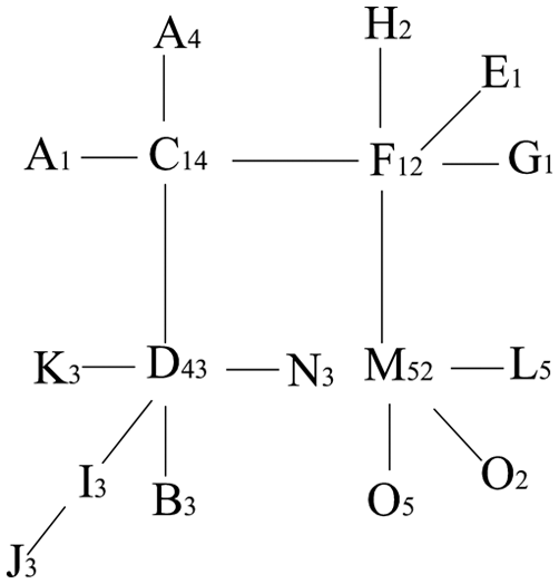
All the surfaces in a gearbox are expressed according to the preceding rules, as shown in Figure 1. The aforementioned description of the surfaces can reveal the surface property. For instance, F12 denotes that surface F is the common contact surface of parts 1 and 2. In this case, surface F belongs not only to part 1 but also to part 2. Moreover, the description can reveal which part each surface is subordinate to. For instance, A1, E1, F12, C14 and G1 all contain the number 1, and thus they all belong to part 1.
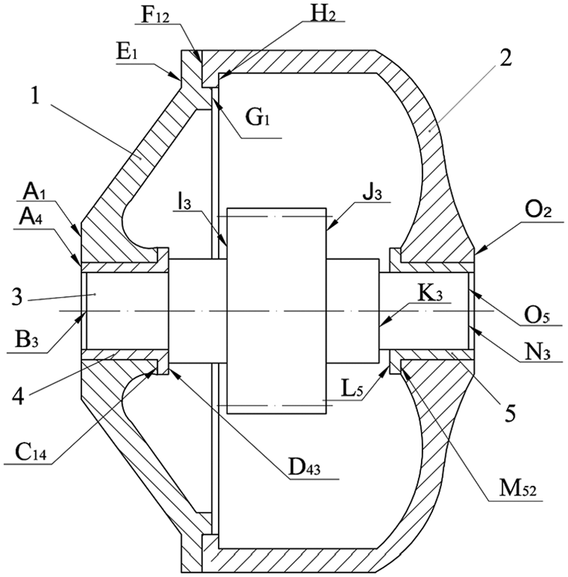
An assembly of a gearbox.
Description of dimensions
In this article, the dimension in an assembly refers to the distance between two surfaces, which can be expressed by a vector of two letters with number subscripts. For instance, the dimension of surfaces A1 and F12 can be expressed as
Functional dimensions of an assembly
The functional dimensions of an assembly refer to the dimensions that must be guaranteed to enable an assembly to function and be properly assembled and maintained. These dimensions can be the design dimension of parts or the dimension between two surfaces of two parts.
Functional dimension
According to their specific characteristics, functional dimensions can be classified into two types:
One or several design dimensions of parts Dimensions that meet the required strength and stiffness in the working process, such as a shaft diameter or gear breadth. Dimensions that are required by the structure or function of parts, such as the raised height of a false boss or a roller length in a roller bed.
Dimensions between two surfaces of two parts Assembly accuracy, such as necessary clearances (or interferences) that make two mating parts work properly, and the alignment dimensions of two meshing gears in the direction of the tooth breadth. Necessary space for assembling, maintaining and moving, such as the necessary space dimension of sliding gears in a gearbox.
Selection principles for functional dimensions
Functional dimensions directly determine the rationality and accuracy of an assembly dimension model. Two principles should be followed when selecting functional dimensions:
Independence. The functional dimensions should be relatively independent of each other. For instance, shaft diameter is required for strength and stiffness when a shaft is mated to a hole. In this case, shaft diameter is a functional dimension. Fit clearance is required for these dimensions to work properly. The two dimensions are evidently independent of each other, and either can be changed at will according to design purpose. However, if the shaft diameter and hole diameter are taken as functional dimensions, then the required clearance of the assembly cannot be guaranteed when the shaft diameter is changed and the hole diameter is kept constant. Thus, the functional dimensions are the shaft diameter and the fit clearance.
Integrity. The integrity of functional dimensions and design dimensions can ensure that a full correlative dimension model can be established.
Every functional dimension has a certain influence on assembly functions. Each functional dimension can be ensured by a corresponding design dimension in a full correlative dimension model, which meets parametric design requirements. If N parts exist in an assembly and part 1 has M1 surfaces in a certain direction, then M1 − 1 design dimensions exist; if part 2 has M2 surfaces …, then M2 − 1 design dimensions exist; and if part N has MN surfaces …, then MN − 1 design dimensions exist. The total number Q of design dimensions is
To establish a full-dimension model that includes all the functional dimensions and design dimensions, the number P of functional dimensions should be equal to the number Q of design dimensions, that is,
Establishing the shortest path graph
Establishing the shortest path graph of functional dimensions is important for obtaining the dimensioning of parts and an assembly dimension model. The subsequent discussions present the process of establishing the shortest path graph.
Preconditions for establishing the shortest path graph
The structure of the assembly must be determinate and correct. The functional dimensions should be selected integrally and correctly and be provided with values and tolerances.
Principles for establishing the shortest path graph
Each functional dimension has its own formative path. Three principles should be followed in the process of establishing the shortest path graph.
Principle 1. The path should be the shortest. The path of each functional dimension should be as short as possible to reduce its accumulative error.
Principle 2. High precision should be given priority. The functional dimensions with the highest precision should have the shortest path. For complex assembly bodies, each functional dimension may be impossible to have the shortest path. Thus, the functional dimensions with the highest precision should be given priority to obtain the shortest path, whereas those with low or zero precision are allowed to have long paths.
Principle 3. One surface can appear only once in a path graph to avoid mutual interference among functional dimensions with different references.
Steps in establishing the shortest path graph
This study uses the assembly of a gearbox (Figure 1) as an example to detail the steps in establishing the shortest path graph.
Surfaces and functional dimensions
This study investigates only the horizontal direction dimension in an assembly. Figure 1 shows five parts with 17 surfaces in an assembly. These components correspond to 16 functional dimensions. According to the assembly and selection principle of functional dimensions, the 16 functional dimensions and the sequence of their precisions are presented in Table 1. In this study, the functional dimensions must be expressed in a positive direction. Thus, the functional dimensions in Table 1 need not be expressed by a vector.
Functional dimensions in Figure 1.
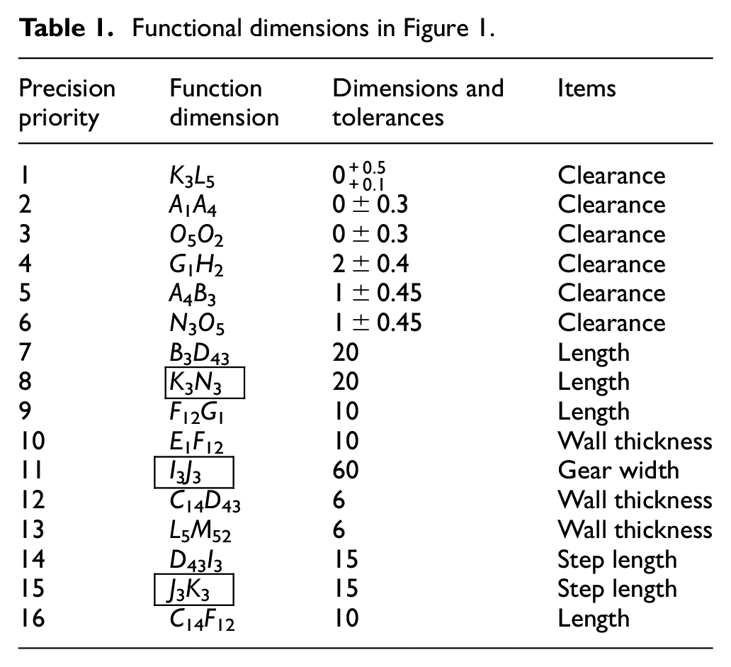
In this assembly, functional dimension K3 L5 is the axial endplay of the gear shaft (No. 1 in Table 1) and is assigned the highest precision. The functional dimension C14 F12 (No. 16 in Table 1) is assigned the lowest precision. The functional dimensions (Nos 7–16 in Table 1) have no accuracy requirement and have free tolerance. The dimensions in the boxes in Table 1 are termed independent functional dimensions, which refer to the part dimensions, and neither of the corresponding surfaces is a contact surface.
Trunk of shortest path graph
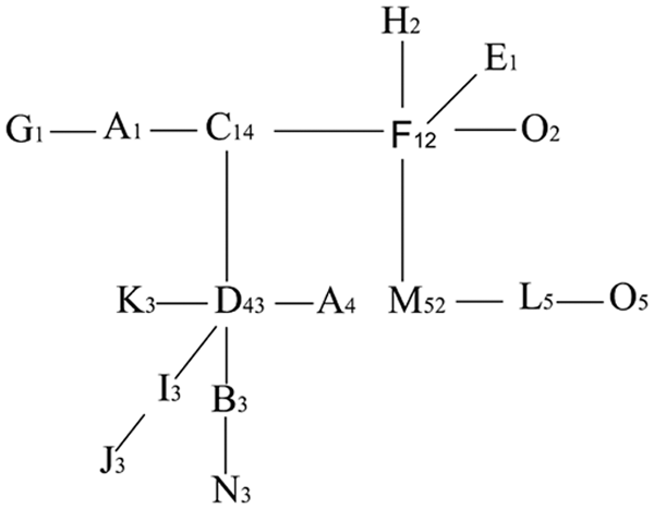
The contact surface of an assembly is an important link in dimension relations. Therefore, a path graph of contact surfaces should be established first. Figure 1 shows four contact surfaces: C14, D43, F12 and M52. A line segment is used to link to the contact surface that has the same subscripts; thus, these four contact surfaces are linked with one another. The path graph that only has contact surfaces is called a trunk (Figure 2). If two or more contact surfaces of a part exist, then two or more trunks also exist. Thus, the final trunk must be determined according to the sequence of the functional dimensions in the assembly (Appendix 1).
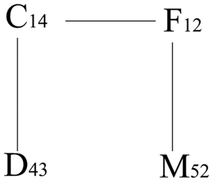
The trunk of the shortest path graph.
Shortest path graph of functional dimensions
When the trunk of the shortest path graph (Figure 2) has been established, the other functional dimensions should be linked. In accordance with the principles that ‘the path should be the shortest’ and ‘high precision should be given priority’, functional dimension K3 L5 is assigned the highest precision; thus, K3 is linked to D43, and L5 is linked to M52 with line segments first. The rest of the functional dimensions are then linked to the path graph according to their precision (Table 1) from high to low until all the corresponding surfaces of all the functional dimensions are linked. The link processes of each functional dimension are shown in Table 2. The following two points should be noted in the link process:
Linking processes of functional dimensions.
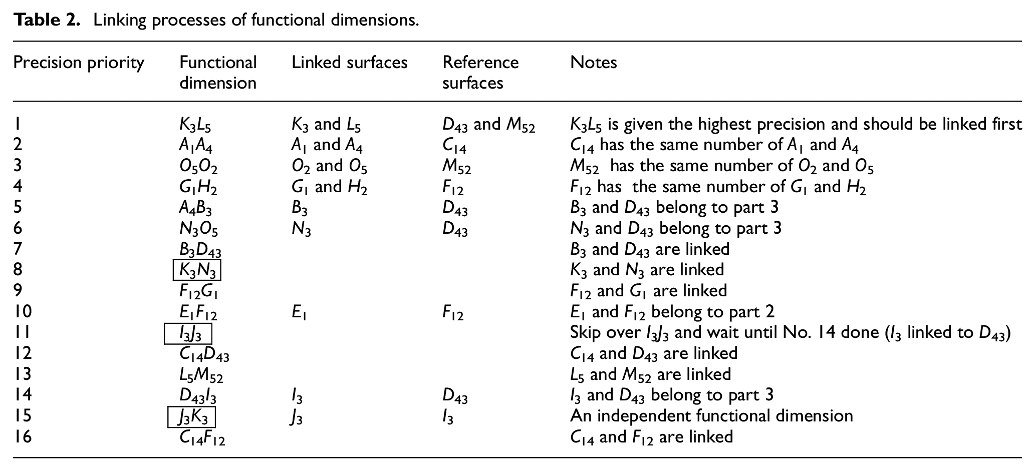
If two corresponding surfaces of functional dimensions and one contact surface have the same number, then both surfaces of functional dimensions should be linked to this contact surface directly according to the principle that ‘the path should be the shortest’. For instance, surfaces G1 and H2 of functional dimension G1 H2 and surface F12 have the numbers 1 and 2, respectively, and G1 and H2 should both be linked to F12 directly (No. 4 in Table 2).
Two surfaces of an independent functional dimension should be linked directly. If the two corresponding surfaces of an independent functional dimension have not been linked, this independent functional dimension should be skipped. The next adjacent functional dimension is then continued to link to the path graph. When either surface of the aforementioned independent functional dimension has been linked, then the two surfaces of this independent functional dimension are directly linked. In the case of I3 J3, neither I3 nor J3 has been linked (No. 11 in Table 2). Thus, I3 J3 is skipped, and the next adjacent functional dimension B3 D43 is linked continuously until I3 of I3 J3 has been linked to D43 (No. 14 in Table 2). Finally, J3 is linked to I3 directly.
The path graph that links all the functional dimensions of the assembly in Table 1 is shown in Figure 3. The path of each functional dimension in this graph must be unique and the shortest possible path. Therefore, this path graph is called the shortest path graph of functional dimensions.
Shortest path graph of functional dimensions.
Revising the shortest path graph
Each edge in the shortest path graph of functional dimensions is a dimension of parts. Thus, the shortest path graph determines the basic dimensioning of each part. However, the specific structure, inspection and dimensioning protocol of each part are excluded. Therefore, the shortest path graph should be revised.
The total length B3 N3 of part 3, A1 G1 of part 1, F12 O2 of part 2, A4 D43 of part 4 and L5 O5 of part 5 require labels. In this case, the two surfaces of these dimensions should be directly linked in Figure 3. For example, B3 and N3 should be linked directly, but according to the principle that ‘one surface can appear only once in the path graph’, the link between N3 and D43 or between B3 and D43 should then be disconnected. The precision of A4 B3 is higher than that of K3 N3 in Table 1. Thus, N3 should be disconnected from D43 and then linked to B3 directly. A1 G1, F12 O2, A4 D43 and L5 O5 can also be addressed in this manner. The revised path graph is shown in Figure 4.
The revised path graph.
Unlike that in Figure 3, the revised path graph in Figure 4 prolongs the formative paths of several functional dimensions. For instance, the path of functional dimension K3 N3 changes from K3 → D43 → N3 to K3 → D43 → B3 → N3. This change results in a larger cumulative error for K3 N3. However, the precision requirement of K3 N3 is low, and the function of the assembly is not overly affected.
Applications of the shortest path graph
The revised path graph not only determines the dimensioning of each part but also establishes a full-dimension model of assembly dimensions.
Dimensioning of each part
If a part has N surfaces, then 2N−1 dimensioning is noted. Every edge in the revised path graph is a design dimension of a part; therefore, the dimensioning of each part is unique. Figure 4 shows all the design dimensions of parts 1, 2, 3, 4 and 5, which are shown in Figure 5(a)–(d). Given that the structure of part 4 is identified with part 5, the dimensioning of part 4 is omitted.
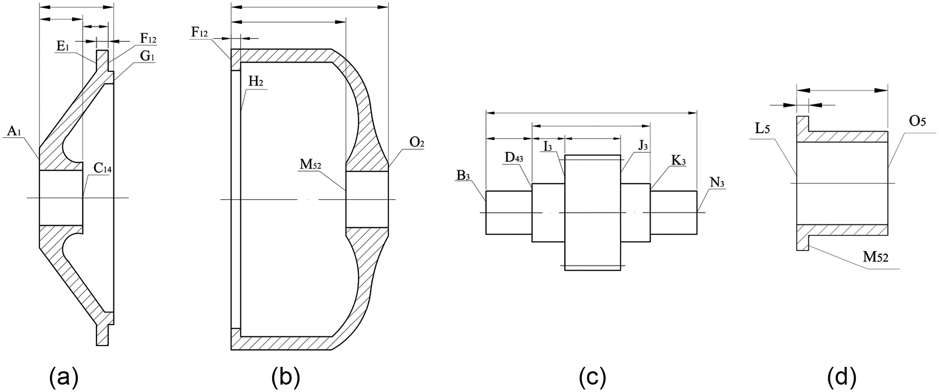
The dimensioning of (a) part 1, (b) part 2, (c) part 3 and (d) part 5.
Full-dimension model
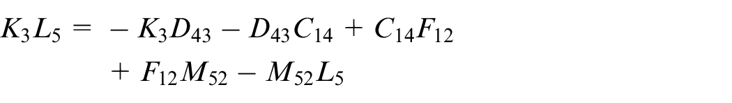
The path graph depicts the formative paths of all the functional dimensions and shows the relations between the functional dimensions and design dimensions of the relevant parts. For instance, the path of functional dimension K3 L5 can be obtained from Figure 4 as follows

The preceding path can be expressed in vector form as follows

The preceding vector formula can be rewritten as the following equation in accordance with the definition of vector direction
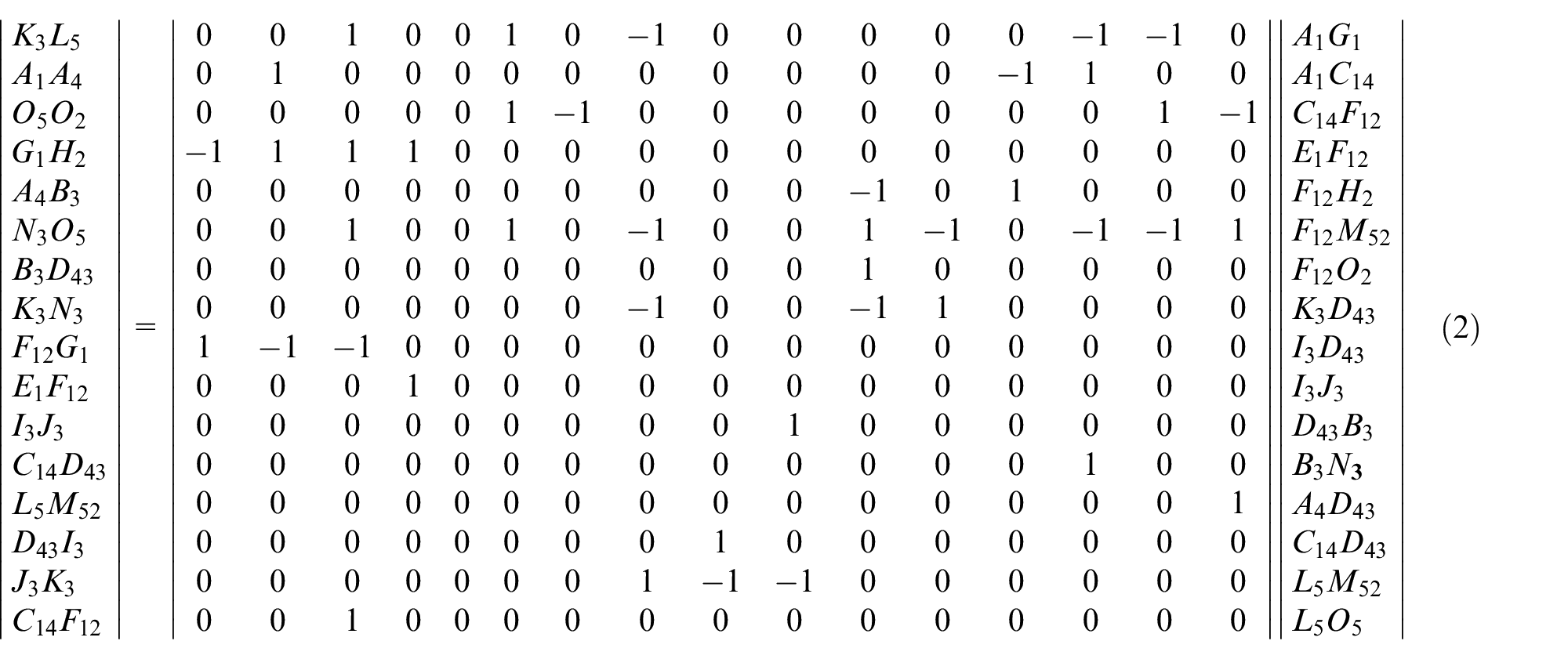
The dimension model of a gearbox in Figure 1 can be expressed as equation (1) according to Figure 4 and the preceding description method. Equation (1) can be rewritten in matrix format as matrix equation (2)
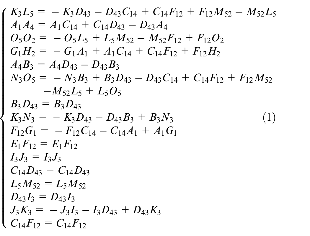
The dimensions and tolerances of the 16 functional dimensions are known; thus, the dimensions and tolerances of the 16 design dimensions can be determined. The total length of the assembly is an important dimension, but it is not in the dimension model. The total assembly length can be obtained according to Figure 4, which can be A1 O2 or A4 O5.
Concluding remarks
The path graph proposed in this article is a new approach that obtains the dimensioning of all the parts in an assembly and a full correlative dimension model. The shortest path graph of functional dimensions is unique when the structure and functional dimension of an assembly are determinate and correct. This condition can effectively guarantee each functional dimension with the smallest cumulative error. The dimension model established on the revised path graph involves all the functional dimensions and all the design dimensions of all the assembly parts. Once the values of one or a few functional dimensions change, the values of the corresponding design dimensions also change, which provides an approach to dimension-driven parameter design.
The proposed approach is suitable only in a certain direction; the assembly exists in a general location, and the path graph and the dimension model are manually established. The dimension model requires further research for over-positioning, planar or spatial assembly. In a complicated assembly, a full path graph of an assembly requires several or more basic path graphs. In this case, grading components and determining functional dimensions are key points and difficulties to be addressed in future research. Future investigation can also focus on how to automatically generate path graphs using an algorithm and how to automatically establish dimension models. The path graph of functional dimensions is a new approach for establishing dimension models and dimensioning parts, and its theory and method require further enhancement.
Footnotes
Appendix 1
Declaration of Conflicting Interests
The author(s) declared no potential conflicts of interest with respect to the research, authorship and/or publication of this article.
Funding
The author(s) disclosed receipt of the following financial support for the research, authorship, and/or publication of this article: This work was supported by the National Natural Science Foundation of China under grant numbers 51175360 and 51575373. The authors appreciate the financial support.