
Abstract
Metallic parts having open cell porous regular interconnected metallic structure of predetermined unit cell are being fabricated using metal powder–based rapid prototyping machines. These machines are capital intensive. All porous structures including open cell porous regular interconnected metallic structure have less density, so they lack in strength problems as compared to the solid structure. The strength of open cell porous regular interconnected metallic structure can be enhanced by providing solid inner core. In this study, a cost-effective technique has been developed to fabricate open cell porous regular interconnected metallic structure with solid core using ceramic powder–based three-dimensional printing machine and pressureless sintering. In this work, two approaches of fabrication were developed. In the first approach, only spherical metal powder was used, while in the second approach, a solid metallic rod along with spherical metal powder was utilized. Interconnected porosity and sinter density of the fabricated specimens were measured using Archimedes’ principle. The characterization was done using microstructure analysis, energy dispersive analysis, scanning electron microscopy and X-ray diffraction analysis. Mechanical properties of developed structures were determined using tensile, compressive and impact tests.
Introduction
Now-a-days, porous material is used in various engineering applications. It includes light weight structure, impact absorbers, flame arrester, silencer, spargers, filters, biocompatible inserts, etc. 1 The extensive use of porous material is due to their excellent mechanical and thermal properties. 2 Based on the opening of cell, the porous material can be divided into two groups: open cell porous and close cell porous structures.2,3 It has been reported that mechanical and thermal properties vary with the opening of cell. The open cell porous structure may be fabricated from metals, polymers or composites. 3 Cheema et al. 4 utilized composite porous layer with higher porosity near wall region in comparison with central region, for improving the performance of electro-osmotic pump. Numerical simulation showed effectiveness of composite porous layer in compensating loss of porosity and improving the performance of device. Various techniques are being employed for fabrication of porous structures. Ryan et al. 5 reviewed the most common techniques for the fabrication of open cell porous structures through sintered metal fibers, sintered metal powder, space holder method, replication, combustion synthesis and plasma spraying, rapid prototyping (RP), etc. Pal and Pal 6 fabricated porous structure with the use of hydroxyapatite (HA) and ultra-high molecular weight polyethylene (UHMWPE) using hot isostatic pressing (HIP). Liu et al. 7 fabricated porous 45S5 bioactive glass–ceramic scaffolds using selective laser sintering.
Metal-based RP processes are the most prevalent techniques now-a-days for the fabrication of open cell porous regular interconnected metallic structure (OCPRIMS). The metal-based RP techniques include laser engineered net shaping (LENS), electron beam melting (EBM), selective laser sintering/selective laser melting (SLS/SLM), etc.8–13 Balla et al.8,9 worked with LENS process to fabricate metallic porous parts of titanium and tantalum suitable to match human bone properties by changing the process parameters such as laser power, scan speed, powder feed rate, layer thickness and hatch distance. Das et al. 10 reviewed the applications of LENS process with the perspective to fabricate porous load-bearing implants. Parthasarathy et al. 11 utilized EBM process for fabrication of open porous interconnected structures of Ti-6Al-4V of varying porosities. The results of tensile and compressive testing showed that tensile and compressive strength increased with decrease in the porosity. Denlinger and Michaleris 12 investigated unwanted distortion in large metallic parts fabricated from EBM. The strategy of adding sacrificial material has been found effective to produce large parts with reduced longitudinal bending distortion. Schoinochoritis et al. 13 reviewed finite element (FE) simulation studies for metallic powder–based bed additive manufacturing processes such as SLS, SLM, EBM. Various numerical modeling techniques such as thermo-mechanical analysis workflow and heat transfer mechanisms were discussed. Simulation results in the form of temperature, residual stress and distortion, melt pool characteristics were also presented. Ahmadi et al. 14 fabricated number of specimens of solid and regular porous structure with diamond lattice unit cell of Ti-6Al-4V using SLM. The results of mechanical properties of the specimens obtained experimentally were compared among the results of analytical and FE models. For small apparent density, experimental results were in agreement with analytical and FE models. While for larger apparent density, experimental results were found in agreement with FE model but disagree with analytical models. Syam et al. 15 recommended the use of metal-based RP techniques such as SLS/SLM, EBM for the fabrication of implants to be used in medicine and dentistry. Wiria et al. 16 fabricated titanium dental implant using three-dimensional printing (3DP) modified machine. Titanium powder along with polyvinyl alcohol (PVA) was used for the fabrication of designed implant. The fabricated implant was sintered thereafter in inert atmosphere.
The mechanical strength of open cell porous material decreases with an increase in the porosity.17–20 Therefore, in order to achieve enhanced strength, Heimann and Wirth 17 applied porous coatings on the solid parts for load-bearing implants. Liu et al. 18 reviewed literature on surface modifications that were applied successfully on titanium and their alloys using thermal spraying, sol–gel, chemical and electrochemical treatments, and ion implantation. Asaoka et al. 19 sintered 0.5 mm thick coating of titanium powder on the solid core. Dewidar and Lim 20 fabricated inner solid and outer porous structures of Ti-6Al-4V with outer porosity of 30%, 50% and 70% through powder metallurgy technique in vacuum atmosphere. Ahn 21 reviewed the trend to use metallic sandwich plates with single layer periodic repeated metallic inner structure (PRMIS) in design, manufacturing and formability with the perspective to reduce weight without compromising strength, stiffness and energy absorption.
The literature survey revealed that OCPRIMS can only be fabricated through metallic RP machines. These machines are high capital intensive. It also represents that the tensile and compressive strength of porous parts can be increased either by decreasing the porosity of the structure or by incorporating inner solid core to the porous structure. So, in order to fabricate OCPRIMS with inner solid core, a technique has been developed which utilizes combination of 3DP (ceramic-based RP machine) and pressureless sintering process. It represents the use of state-of-art technology with fair cost. Two different methodologies are used in the fabrication process; in the first method, only spherical metallic powder is used, while in the other method, solid rod along with spherical metallic powder is used. Determination of sintered density, interconnected porosity for both types of fabricated structures has been carried out. Characterization of structures was done by microstructure analysis, scanning electron microcopy (SEM), X-ray diffractions (XRDs) and energy dispersive X-ray analysis. Tensile, compressive and Charpy tests were performed to establish mechanical properties of the fabricated structures.
Materials and methodology developed
Fabrication procedure
With the objective to fabricate solid inner core with outer OCPRIMS, inverse computer-aided design (CAD) drawings of required structures were modeled. As per the planned technique, required metallic structure would be the inverse of CAD/3DP model. So, in order to fabricate targeted structure, three different CAD models having outer size 25.2 × 12.2 × 12.2 mm3, strut diameter of 1 mm and pores of 1.2 × 1.2 mm2 were modeled using SOLIDWORKS 2004. The main difference in the CAD models was of the size of square through hole which varied from 2.2 × 2.2 mm2 to 6.6 × 6.6 mm2. The CAD model with central through hole of 6.6 × 6.6 mm2 is shown in Figure 1.
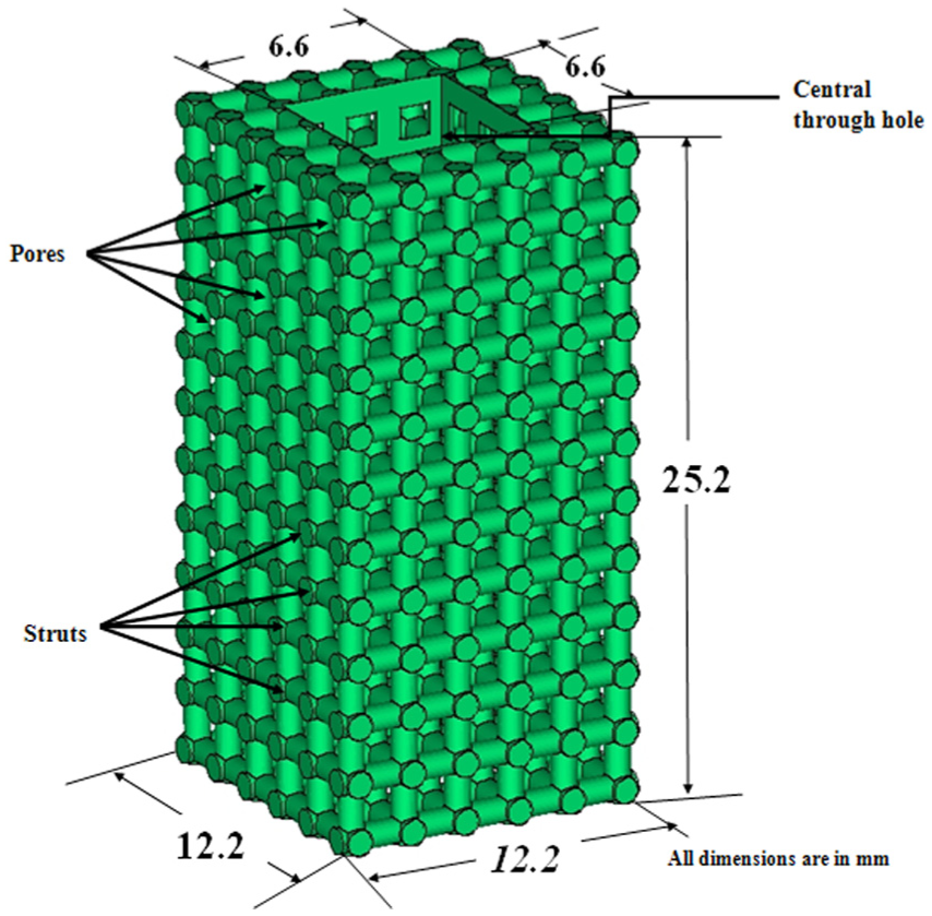
CAD model of specimen with 6.6 × 6.6 mm2 square through hole.
The details of CAD models are summarized in Table 1.
Dimensional details of CAD models.
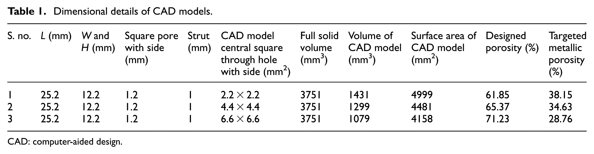
CAD: computer-aided design.
As per CAD design, physical models were fabricated using 3DP (spectrum 510; Z-corps, USA). Patented material (ZB 131, Z-corps) with clear binder (Zb® 63, Z-corps) were used during layer-to-layer deposition. Layer thickness of 0.1 mm was used in the fabrication process. Thereafter, fabricated models were dipped for 2 s in patented binder (Z-bond TM-90) for strength enhancement. A total of 18 specimens, 6 from each CAD model, were fabricated. Two approaches were tried in this work. In the first approach, only spherical phosphor bronze of 150–250 µ size (purchased from M/s SLM India, Orissa) was used while in second approach, cold worked solid bronze rod (C51100) with temper designation H04 in accordance with ASTM B103/B103M-10:2010 22 and spherical phosphor bronze powder were utilized. The properties of spherical bronze powder and C51100 are shown in Table 2.
Properties of spherical phosphor bronze powder and bronze rod C51100.
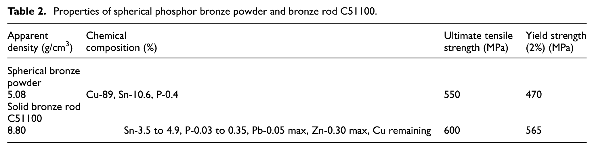
The spherical powder was used in the process as it allowed neck-to-neck fusion in pressureless sintering during the use of rod-facilitated solid structure at the inner core. Using first methodology, nine specimens, three from each design were wrapped with reflecting tape and backed with plaster of Paris. One side of the model remained open to facilitate inflow of metallic powder. In the second methodology, cylindrical phosphor bronze rod of diameter 2, 4 and 6 mm were inserted into central through hole in the rest of designed nine specimens. Thereafter, these were also backed with plaster of Paris mold keeping one side open. All the molds (received from first and second approaches) were filled with spherical metal powder of phosphor bronze and vibrated using vibrator for 10 min so that settling of powder in between the spaces could take place. For arriving suitable sintering temperature and hold on time, various sintering cycles were tried with additional specimens. The temperature was selected within the range of 800 °C–870 °C and hold on time from 30 min to 2 h in accordance with ASTM B925-08:2008. 23 The sintering temperature of 835 °C was found suitable for specimens obtained from two methodologies. The hold on time of 1 h was observed appropriate for powdered specimens, and 1 h 30 min for solid rod–powdered specimens. The reason of taking 30 min extra hold on time was due to the inserted solid rod which took time to soak the heat prior to sinter. The suitable sintering cycles are shown in Figure 2.
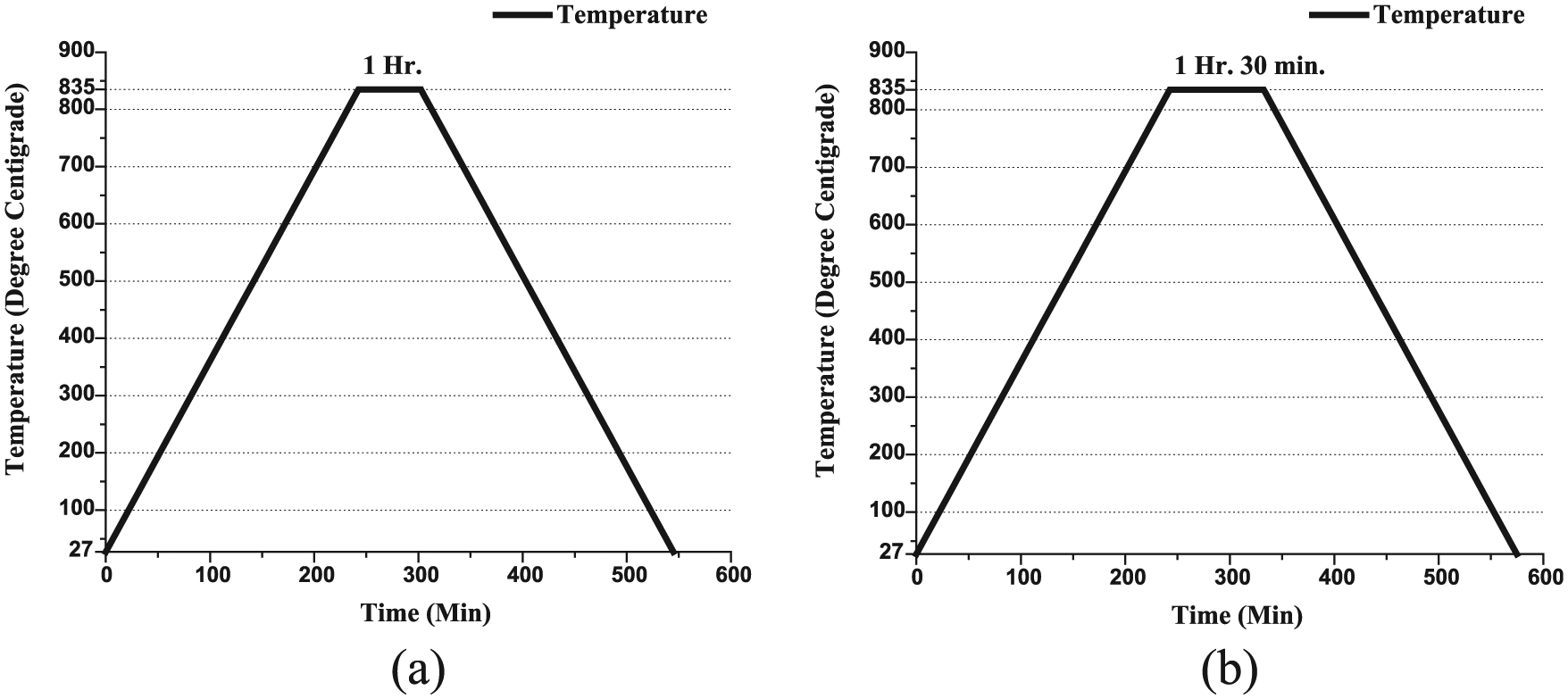
Suitable sintering cycles for (a) powdered specimens and (b) rod-powdered specimens.
The molds were kept and sintered at suitable parameters in the tube furnace (M/s Metrex Instruments, Delhi) under inert argon atmosphere. The sintered specimens were taken out from the mold and washed with high pressure of water. The pores were cleaned with pricking needles. The details of fabrication process are shown in Figure 3.
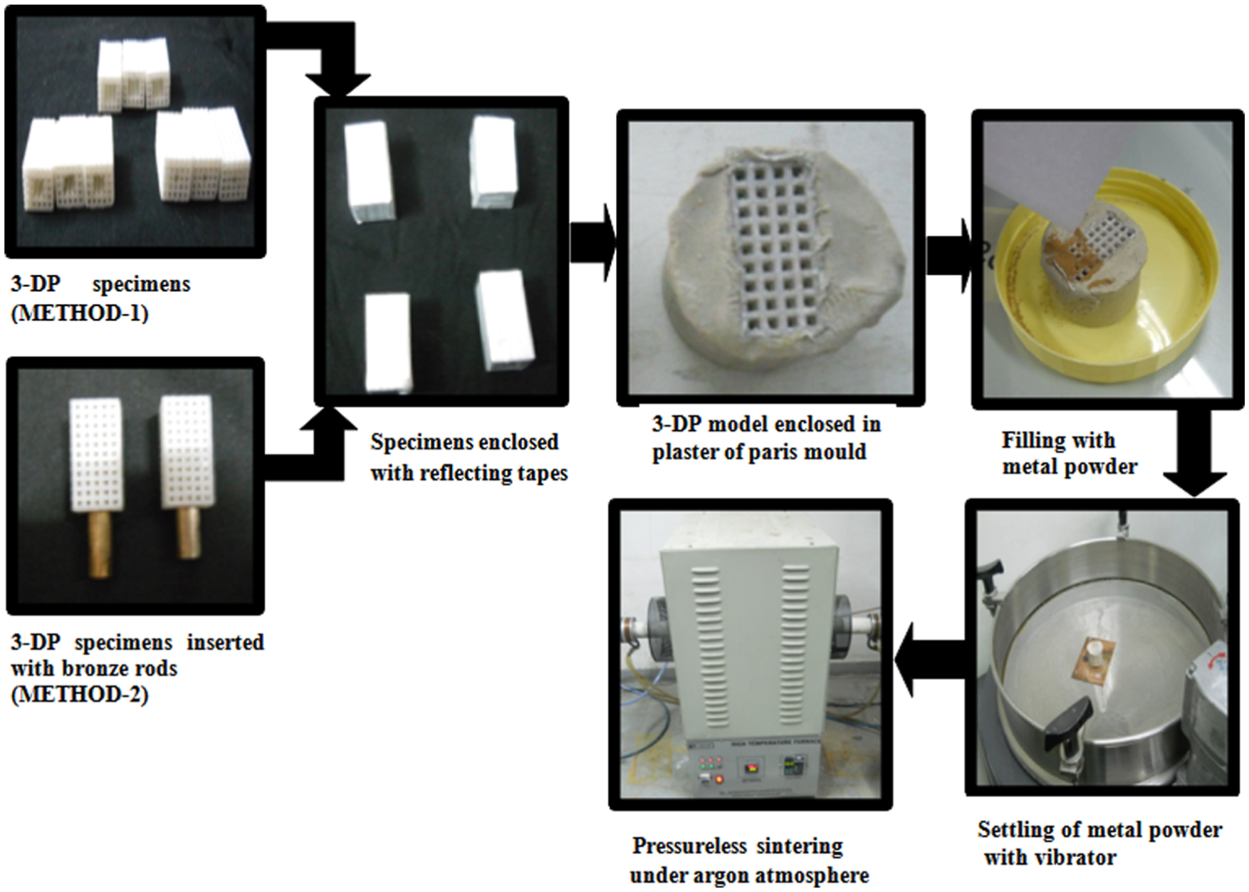
Fabrication details of inner solid with outer OCPRIMS.
Using both the methods, a total of 18 specimens were fabricated. Nine specimens, three from each design, were having powdered core and remaining nine, three from each design, were with bronze rod cored with outer OCPRIMS. The fabricated specimens were inverse of CAD models/3D-printed models. The inner square core through holes was changed into solid inner core while outer pores became strut and vice-versa. The pictures of two types of fabricated structures are shown in Figure 4.
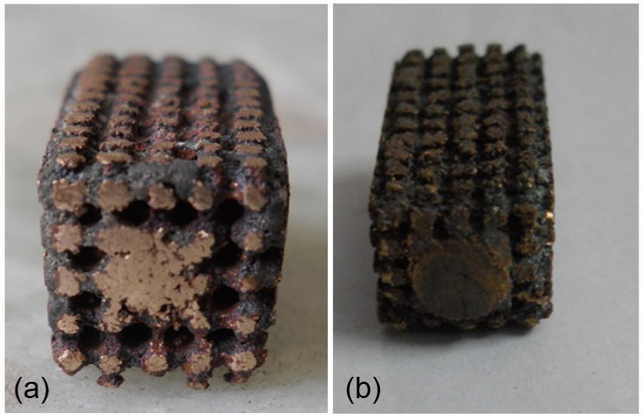
Fabricated specimens of solid inner core with outer OCPRIMS: (a) powdered specimen and (b) rod-powdered specimen.
Further impact and tensile specimens as per ASTM B925-08:2008 23 were also fabricated using both the methods.
Determination of sintered density and interconnected porosity
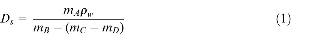
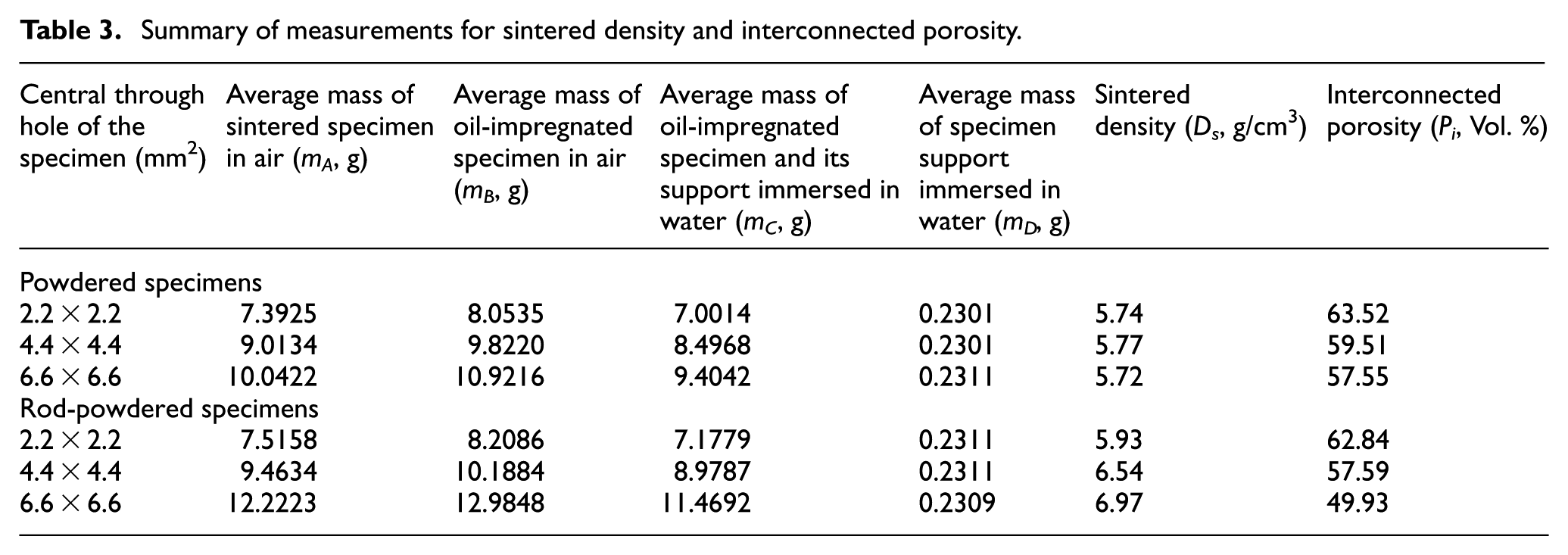
Sintered density and interconnected porosity of the fabricated specimens were calculated using Archimedes’ principle. The specimens were taken and weighted thrice in air using electronic balance (M/s Shimadzu corporation, Koto, Japan) having capacity of 200 g with sensitivity of 0.0001 g. Thereafter, the specimens were impregnated in oil of viscosity of 32 cSt and density of 0.87 g/cm3 in vacuum at reduced pressure of 7 KPa (vacuum). After 30 min in vacuum, the specimens were exposed to atmospheric pressure for 10 min. The oil-impregnated specimens were weighted in air. After applying reflecting tape on the outer surface on the specimens, impregnated oil was poured and allowed to settle in the pores. Ultrasonic vibrations were applied in order to escape the air bubbles from oil. Thereafter, specimens were weighted in water with the help of copper wire of 0.12 mm diameter and enclosed tapes (support). The temperature of water was measured using thermometer. Based on measured masses, sintered density (
Summary of measurements for sintered density and interconnected porosity.
Characterization and determination of mechanical properties
The SEM was performed using ZEISS EVO Series Scanning Electron Microscope (Model EVO 50) and energy dispersive X-ray (EDX) analysis using Bruker-AXS Energy Dispersive X-ray System (Model QuanTax 200). Photomicrographs were taken to assess the phase formation. XRD was carried out (PANanlytical X’pert 3 power Almero Netherland) for characterizing the behavior and stability of the process. The dimensions of inner core were measured with the help of coordinate measuring machine (Carl zessis, Germany operated with calypso software V 4.6). Tensile and compressive strength tests were conducted with the help of universal testing machine (MTS 858) and for impact properties, Charpy test (AVERY, Birmingham, UK) was also performed.
Results and discussion
Determination of sintered density and interconnected porosity
Sintered density and interconnected porosity were evaluated in accordance with ASTM B962-13:2013
24
and ASTM B963-13:2013
25
using equations (1) and (2), respectively. Each measurement was taken thrice and average of three was considered for subsequent calculations. The temperature of water was measured and found to be 30 °C; therefore, the density of water (
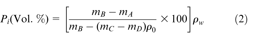
From Table 3, it can be seen that average sintered density of the porous structures fabricated through powder varies from only 5.71 to 5.77 g/cm3 with the increase in inner square core of 2.2 × 2.2 mm2 to 6.6 × 6.6 mm2. The average sintered density of rod-powder porous structure varied from 5.93 to 6.97 g/cm3, for the same increase in the size of the inner square core. For better understanding of this phenomenon, diagram shown in Figure 5 can be referred. Figure 5(a) shows the total volume of specimen (V) as the sum of volume of inner core (V4) and outer OCPRIMS (V3). As the volume of inner core (V4) increased from 2.2 × 2.2 mm2 to 6.6 × 6.6 mm2, the volume of outer OCPRIMS (V3) decreased, thereby decreased the interconnected porosity from 63.52% to 57.55% while the average sintered density of the powdered-cored specimen remained nearly unaffected (5.71–5.77 g/cm3). This was due to the fact that sintered structure of the powder contained shrinkage cavities throughout (both in the core area and in the outer structure) as evident from the SEM images (Figure 6(a) and (b)). In rod-powdered specimen shown in Figure 5(b), the total volume (V1) is a sum of inner core volume consisting the volume of solid rod core (V2), volume of powdered core (V5) and outer OCPRIMS (V6). With the increase in inner core structure from 2.2 × 2.2 mm2 to 6.6 × 6.6 mm2 (containing the solid rod of diameter 2–6 mm and sintered powder), the porosity of the specimen decreased from 62.84% to 49.93%. The decrease of porosity in rod cored structure was found on the higher side in comparison with powdered-cored structure due to the presence of solid rod (V2) without shrinkage cavities/voids. The same can be seen in the SEM images in Figure 6(c) and (d). The average sintered density of the solid rod cored specimen was found to be increased from 5.93 to 6.97 g/cm3 with the increase in solid rod diameter from 2 to 6 mm. This was due to the fact that solid bronze rod has density of 8.8 g/cm3 and did not has any shrinkage cavity which resulted into significant increase in the average density of these specimens.
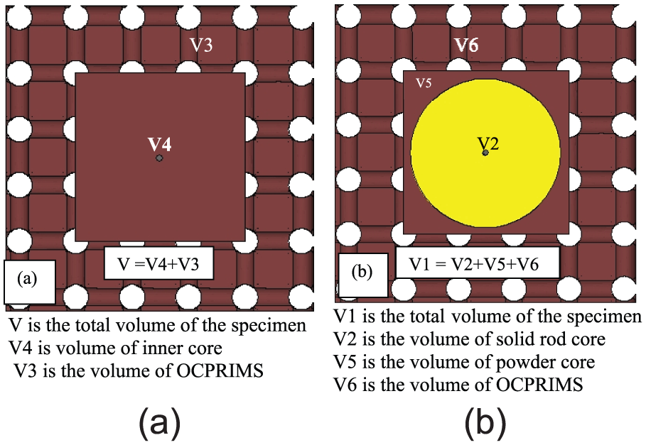
Schematic representation of solid inner and outer OCPRIMS: (a) powered specimen and (b) rod-powdered specimen.
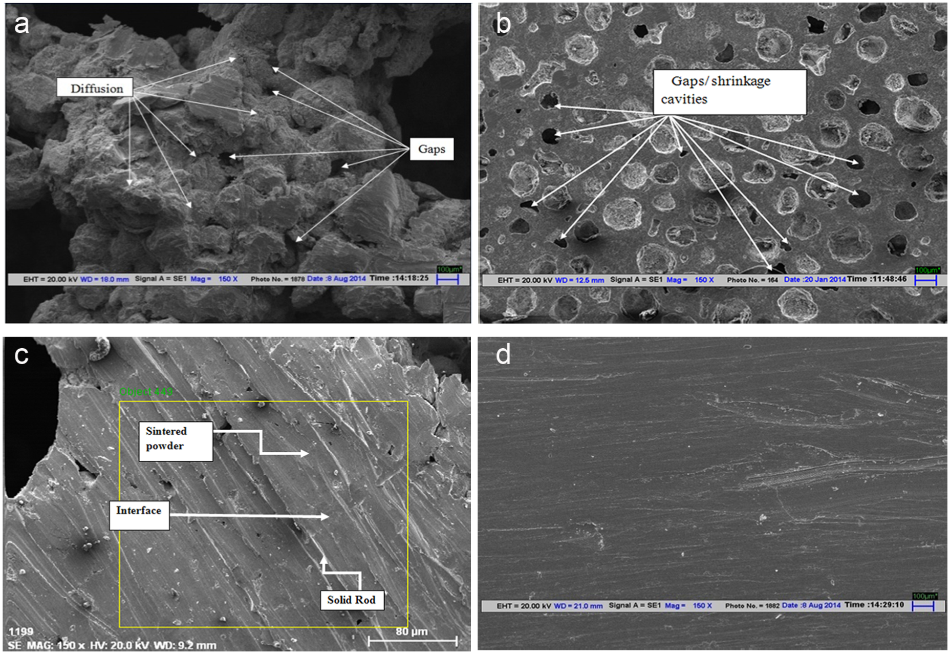
SEM images of sintered structures at different locations: (a) outer OCPRIMS 150×, (b) inner powdered core 150×, (c) interface of solid rod powder 150× and (d) solid rod core 150×.
Characterization of the fabricated specimens
In this developed technique, pressureless sintering has been prominent in both the used methodologies. It is characterized by fusion within spherical metal particles as well as with solid rod by heating below its melting point as shown in SEM images (Figure 6). During sintering, the growth of neck formation between the spherical powders and contacted surfaces took place initially and subsequently grow thickened due to diffusion of the atoms. The strength and rigidity were the outcome of growth and diffusion of sintered structure. The curvature and shape of the metal particles were responsible for diffusion movement among atoms which resulted in lowering of surface energy. Small size particles had high surface energy in comparison with the large size particles. Therefore, it allowed sintering of small size particles at low temperature. 26 But for rod-powder structures, the dimensions of inserted rods were very large in size in comparison with metallic powder, so they had a very low surface energy. Further tin content in the solid rod was low in comparison with powder.
At temperature above 246 °C, a pool of tin was formed due to melting which diffused to the neighboring copper atoms forming neck in the initial stage. In the solid rod, phenomenon of melting tin was at the surface than at the center. It allowed fusion of metallic powder with solid rod in contact. Solid boundaries were formed between the contacted surfaces having grain boundary energies. Due to misorientation of grains, atoms had varying grain boundary energy. For achieving low grain boundary energy, they rotated and rearranged during sintering. 26 During rotation or rearrangement, shrinkage took place in the powdered structure. However, in solid rod, no such rearrangement took place.
Phosphor bronze, wherein liquid phase sintering took place, had caused wetting of solid surface and formation of capillary stress. This stress broke the initially formed necks and resulted in a pull among the particles causing further shrinkage. 26 The density of the sintered powdered structure was increased while the density of solid rod remained unaffected. The present pores were reduced due to the grain growth; however, they remained present outside grain boundaries in reduced form. On cooling, the pores got distributed along the grain boundaries. Figure 6(a) shows the evidence of sintered powdered structure showing gaps and diffused structure.
The central core formed by the powder had fewer gaps as compared to the sintered structure of outer OCPRIMS as shown in Figure 6(a) and (b). The surface of solid rod has completely diffused with the spherical powder showing complete sintering of solid rod with powder. The solid rod, interface and sintered powdered structure are shown in Figure 6(c). However, solid rod structure shown in Figure 6(d) shows no voids and represents denser structure. On comparison of the SEM images, Figure 6(b) and (d) clearly explicit that solid rod inner core has no/very less porosity in comparison with the powdered inner core.
In order to assess the stability of the process, phase transformation of phosphor bronze was studied. The phase diagram of 90Cu10Sn and 95Cu4sn showed formation of α-bronze after sintering. 27 The diffusion of tin atoms with copper during sintering resulted in formation of α-bronze. In order to study the phases present in the sintered specimens, the specimens were molded and hot pressed in bakelite powder. The specimen was grounded with variable grit of emery papers and swapped with mixture of distilled water (200 g), ferric chloride (10 g) and hydrochloric acid (50 ml). The Same were viewed under optical microscope at different locations. The obtained microstructure at 2500× was compared with the microstructure showed in ASTM STP 323:1962. 28 It was confirmed that formation of α-bronze had taken place and the results were in agreement with ASTM standard. The photomicrographs of the same are shown in Figure 7.
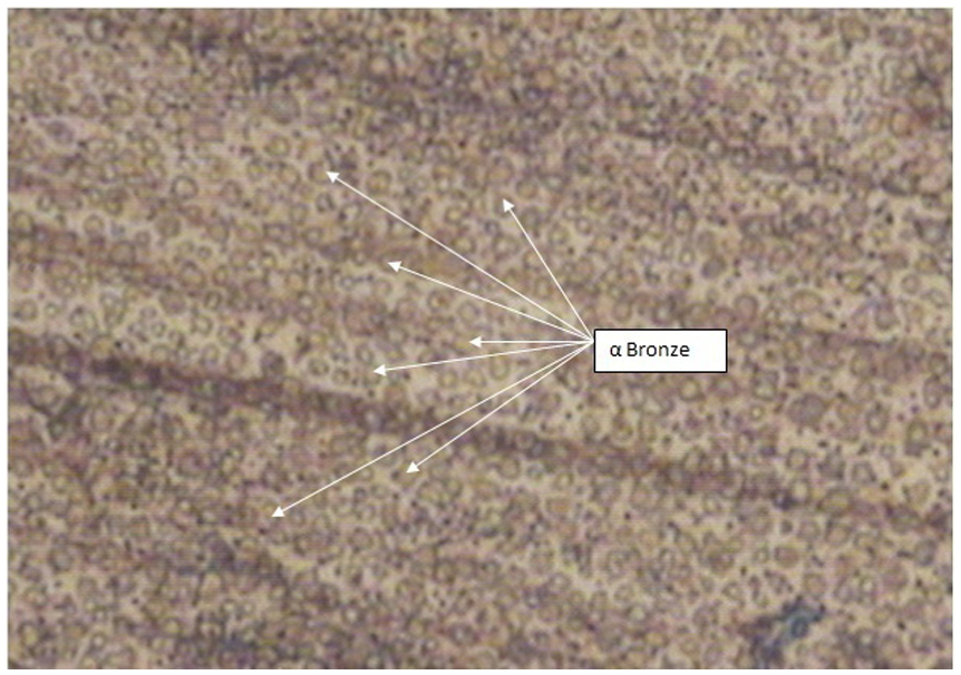
Microstructure of α-bronze 2500×.
In order to further confirm the formation of α-bronze, XRD of the sintered structure was carried out in the sintered powder portion and separately at the solid rod portion. The obtained pattern shown in Figure 8 was compared with the standard, JCPDS Card Alpha: 04-0836. 29
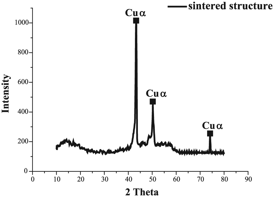
X-ray diffraction pattern of sintered structure.
The comparison confirms face-centered cubic (FCC) lattice with α-phase in the sintered bronze. However, the peaks of sintered solid rod as well as sintered powdered structure were found to lie within the range of ±0.215° of 2θ scale.
In order to ascertain the chemical composition, EDX analysis was carried out at different stages and locations to assess the elemental constituents in the fabricated structure. In the solid rod structure, no substantial change in the composition was observed. The obtained EDX of powdered structure is shown in Figure 9.
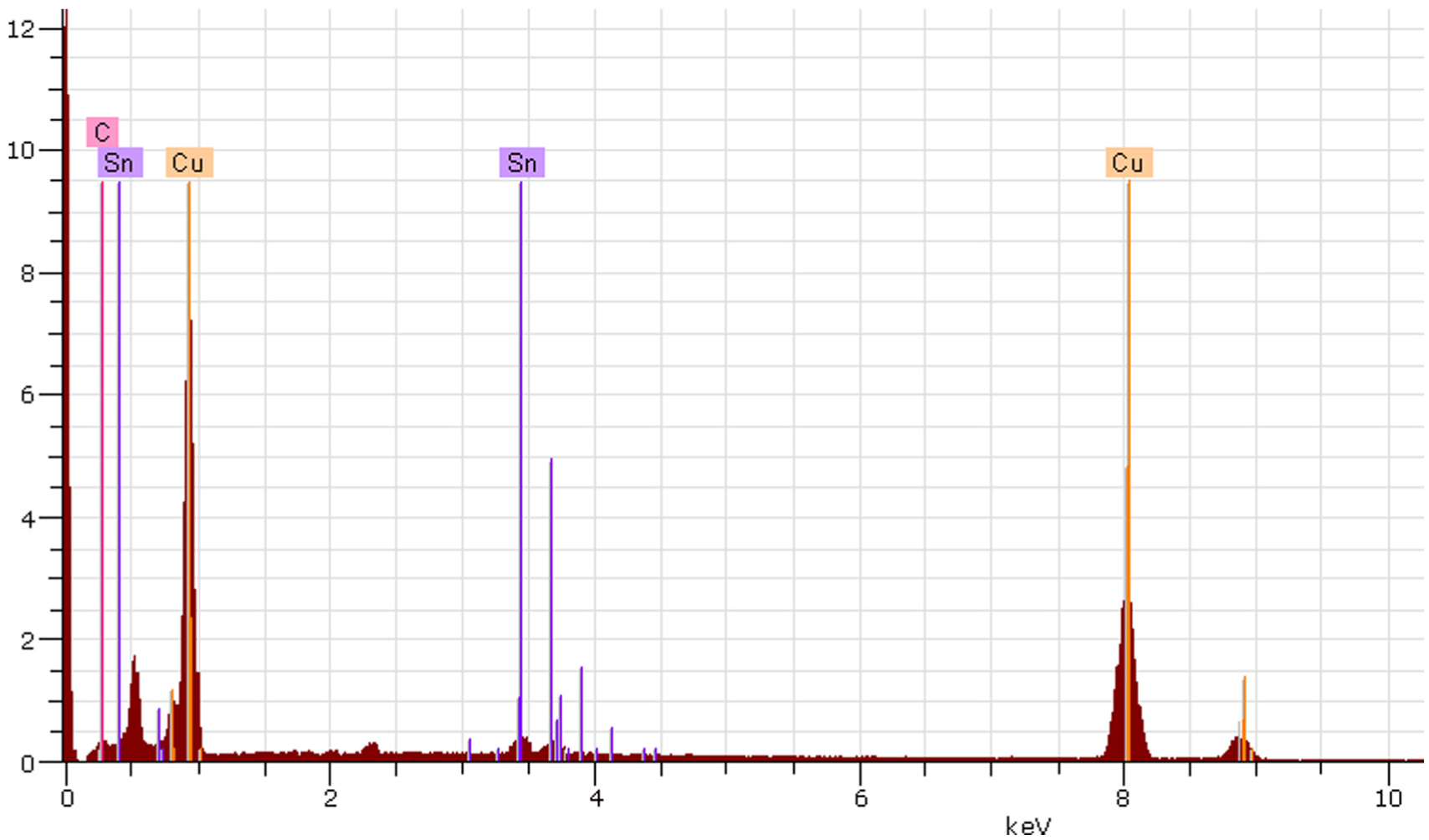
EDX of sintered structure.
The EDX shows copper 89.55%, tin 8.29% and carbon 2.12% in the sintered structure. It has been observed that carbon was the new constituent that was added during the process. The addition of carbon in the sintered structure may be due to the combustion of reflecting tape and heating of patented 3DP material (ZB 131, Z-corps). However, the presence of carbon in the sintered structure of bronze has been reported to be beneficial as it facilitates the self-lubrication. 27
The characterization of the pressureless sintered structure revealed the presence of voids in the sintered powdered structure. The voids were found more in the outer OCPRIMS than at the inner powdered core. This may be due to the effective heat transfer in the inner core which might promote liquid phase sintering to close the present voids among the spherical metal powder. However, heat transfer at the outer OCPRIMS may be little affected due to the presence of close 3DP mesh structure. This confirmed the stability of the developed process.
Mechanical properties
Mechanical properties are important for exploring the usability of fabricated structure. So, in order to evaluate the same, compressive, tensile and Charpy tests were conducted.
Compressive testing
The compressive tests were performed on the fabricated specimens as per design and methods explained in the earlier sections. Three specimens of each design were tested to ensure repeatability. Universal testing machine (MTS 858) was used to test the compressive strength at the cross travel speed of 1 mm/min. The results obtained in these tests are presented in Figure 10.
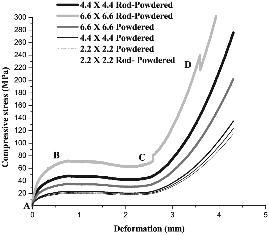
Compressive testing of inner solid core with outer OCPRIMS.
Figure 10 shows the initial increase in the stress (A to B) with an increase in the deformation for all the specimens. In this region, main resistance offered against deformation was by the inner core while outer porous side was under deformation stage. Thereafter, a region of constant stress (B to C) called plateau stress has been followed. This region shows the capability of porous structure for absorbing energy. In this region, inner core along with outer porous structure was under deformation. On further deformation, a proportionate increase in the compressive stress was observed (C to D) for all the compressed fully and posed more resistance against the deformation. The value of plateau stress was found to be increased with an increase in the solid inner core diameter. The trends of results are similar and are in line with the other researchers. 20 On comparison, the values of plateau stress for inner solid rod cored structure were found on the higher side than the inner powdered cored structure. This difference in plateau stresses was found less for inner core 2.2 × 2.2 mm2 but it increases with increases in inner core. The plateau stress for the specimens with solid rod inner core of 4.4 × 4.4 mm2 was at higher side than the powdered inner core of 6.6 × 6.6 mm2. It has been found dependent upon interconnected porosity and sintered density of the specimen. This may be due to the fact that solid rod does not contain any porosity and contribute to specimen to have high sintered density, thereby offering more resistance to deformation. Voids were observed in the powdered core which contributes to have high porosity with low sintered density in comparison with solid rod inner core and offers less resistance to deformation. The behavior of the curve has been found to be similar to the open cell porous structure and can be predicted by the following relationship given by Ashby et al. 3
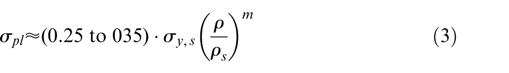
where
Compressive strength of inner solid core with outer OCPRIMS.
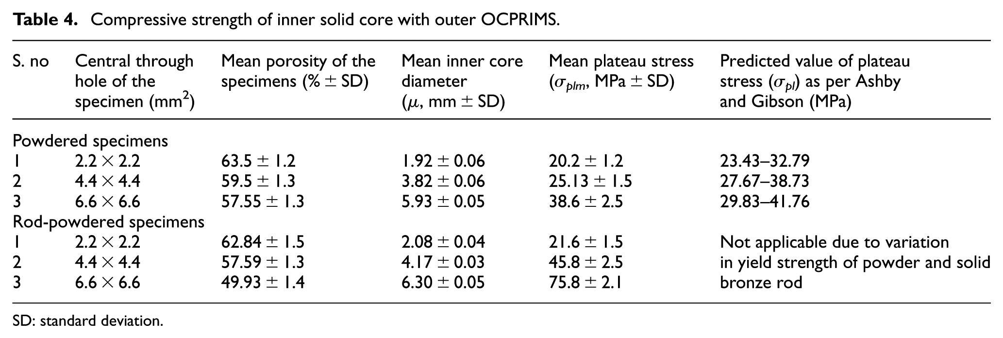
SD: standard deviation.
From Table 4, it can be seen that with an increase in the porosity, the compressive strength decreases. The experimental results of powdered specimens having inner core of 2.2 × 2.2 mm2 and 4.4 × 4.4 mm2 showed disagreement with Ashby and Gibson equation. The predicted values were higher than the obtained experimental results. While specimens with inner core 6.6 × 6.6 mm2 showed in agreement. This may be due to the fact that increased inner core had posed more resistance to deformation, thereby increasing compressive stress. The results of open cell regular structure of Ti-6Al-4V fabricated from EBM also showed disagreement with Ashby and Gibson which are in line with other researchers. 11 The results of rod-powdered specimens could not be compared with Ashby and Gibson equation as solid bronze rod and used powder have different yield strength.
Tensile testing
In order to evaluate tensile strength, specimens with inner core of 2.5 mm diameter with outer OCPRIMS were fabricated as per the developed methods. Solid rod of 2 mm diameter was used in rod-powdered structure. The outer dimensions confirm in accordance with ASTM B925-08:2008. 23 Three specimens for each design, total six specimens were fabricated and tested using universal testing machine (MTS 858). The cross table speed was kept as 1 mm/min. The results of tensile testing are presented in Figure 11.
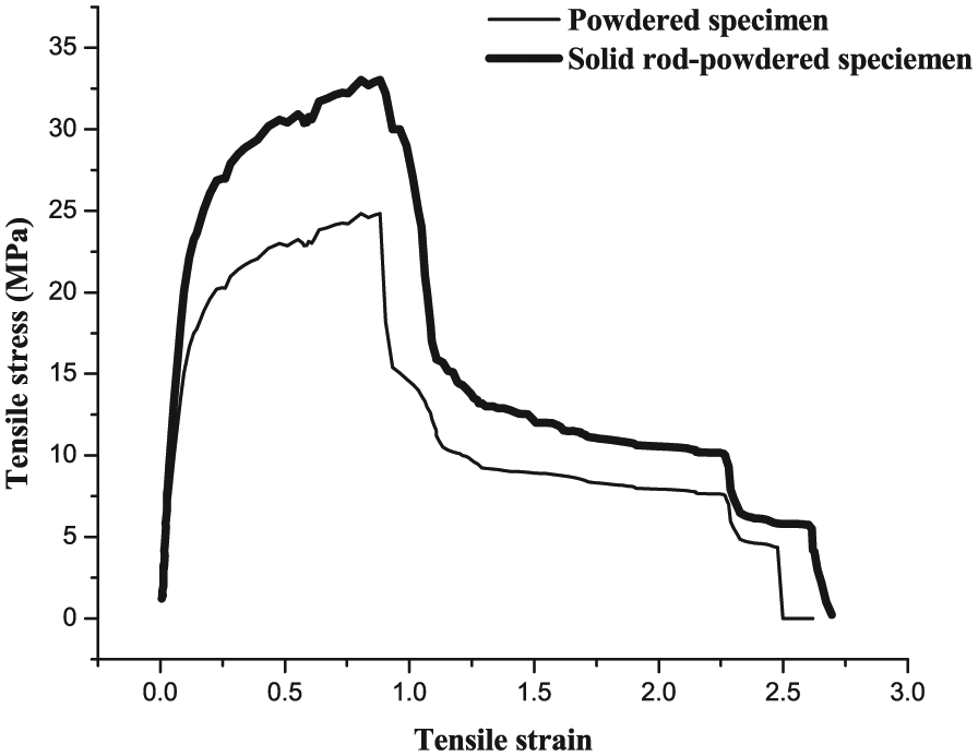
Test results of tensile testing.
It can be seen from Figure 11 that with an increase in tensile strain, tensile stress increased initially thereafter it stabilizes to a certain extent. On further increase in tensile strain, tensile stress decreases. The solid rod–powdered structure showed higher values of tensile stress in comparison with the powdered structure. The obtained results were found similar in trend with open cell porous aluminum foams (Alulight). The comparison of the experimental results could not be ascertained due to lack of analytical tensile equation, for metal foam in the literature (Table 5).
Tensile strength of solid inner and outer OCPRIMS.
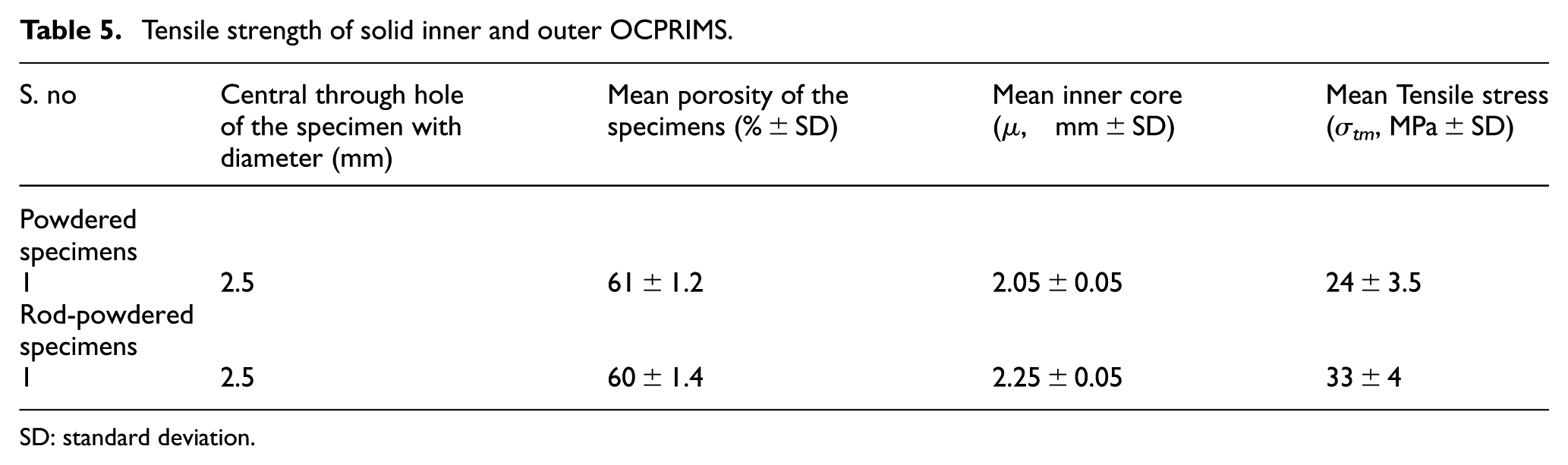
SD: standard deviation.
Impact testing
For evaluating impact strength, Charpy un-notched specimen 3 in number for each design in accordance with Figure 1 (powder and solid rod–powdered) with inner core of 2.2 × 2.2 mm2, 4.4 × 4.4 mm2 and 6.6 × 6.6 mm2 having outer dimensions of 7.5 × 10 × 10 mm3 as per ASTM B925-08:2008 23 were fabricated using both the methods. The fabricated impact specimens are shown in Figure 12. Charpy test was conducted in accordance with ASTM E23:2000 30 using impact testing machine (AVERY) with striking velocity of 5 m/s.
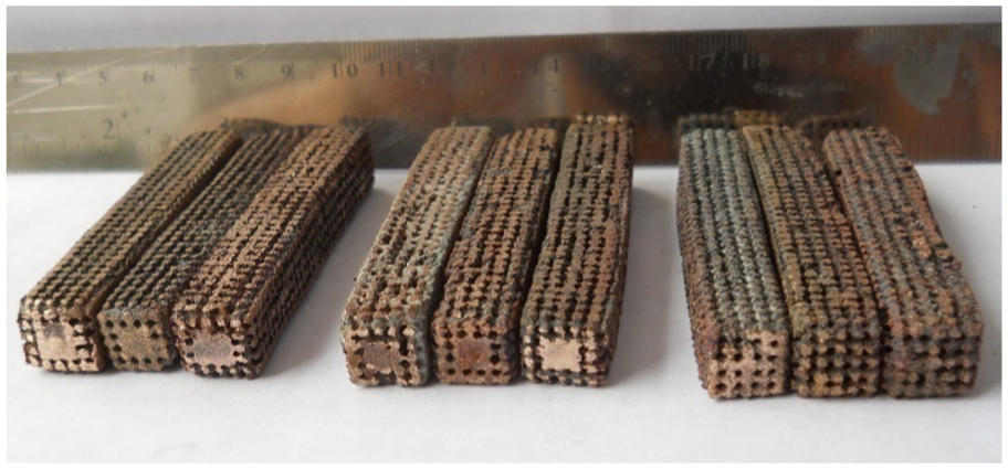
Impact specimens.
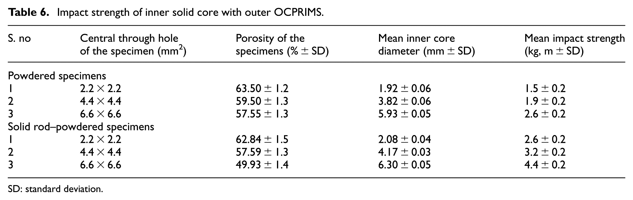
The average of three impact strength values has been considered for evaluating impact properties. Details of impact strength values obtained have been summarized in Table 6.
Impact strength of inner solid core with outer OCPRIMS.
SD: standard deviation.
It can be seen from Table 6 that the solid rod–powdered specimens with similar interconnected porosity have higher impact values than the powdered structure. This may be due to the fact that inner rod core has higher density and no voids were present in the solid rod. This offers more resistance to the impact than the powdered structure. The comparison with the data could not be carried out with impact strength values due to lack of literature.
Conclusion
From the above experimental studies, the following conclusions can be drawn:
The feasibility has been explored successfully using metallic powder and rod powder, for fabrication of solid inner and outer OCPRIMS through 3DP and pressureless sintering.
The interconnected porosity and sintered density of the sintered structure have been found to be increased. The sinter density of the powdered structure has been increased from 5.04 to 5.77 g/cm3 while sintered density of rod-powder structure has been found to be 5.92–6.97 g/cm3. The interconnected porosity of the fabricated specimens has found in the order of 49%–63% against the targeted 28%–38%.
The characterization of the fabricated specimens showed the behavior of pressureless sintering process used for sintering spherical powders. Microstructure, XRD analysis, SEM, EDX characterized the sintered bronze structure by formation of gaps, presence of α-bronze and presence of small amount of carbon in it. The results are in line with the available literature. It reveals that the process is stable and showed its suitability for sintering metallic powder with solid pieces.
The mechanical testing showed that the inner solid core with outer OCPRIMS follows the behavior of open cell porous material and strength of OCPRIMS can be enhanced by incorporating solid inner core. These are found to be increased with the increase in inner core diameter which is in line with the findings of other researchers. The mechanical properties of the solid rod inner cored structure have been found to be at the higher level than the powdered inner cored structure.
Footnotes
Appendix 1
Acknowledgements
The authors are thankful to the Indian Institute of Technology Delhi for providing them the rapid prototyping lab, mechanical lab, metrology lab, central facilities and DFM lab for conducting experiments and analysis work.
Declaration of conflicting interests
The author(s) declared no potential conflicts of interest with respect to the research, authorship and/or publication of this article.
Funding
The author(s) received no financial support for the research, authorship and/or publication of this article.