
Abstract
Sheet metal parts are widely used in the manufacturing industry. With the number of 3D models increasing, it is essential to retrieve existing resources. Effective similarity assessment would be useful in many downstream applications, such as design reuse and manufacture process revision. We propose a hierarchical representation and similarity assessment algorithm to retrieve 3D models of sheet metal parts. Based on single-side representation extracted from solid models, flat and bent faces are recognized and clustered into groups. The morphological relationship between these two groups is then described and an attributed graph is built to store the connection between flat groups. A hierarchical representation is derived by a simplification and assembly process. This structure supports similarity assessment in different levels of detail; thus, a multiple-resolution formula is introduced to measure the total similarity. The algorithms were implemented based on a neutral standard for the exchange of product model data (STEP) format and a prototype demonstrates the application in shape search and reuse in manufacturing industry.
Introduction
Sheet metal parts are widely used in the manufacturing industry, e.g. to build automobile, aeroplane and consumer electronics products. In many factories, 3D models are basic elements of computer integrated manufacturing, which support intuitive engineering changes, manufacturing design and process planning. With the number of 3D models increasing, the effective and efficient representation and retrieval of existing sheet metal parts is essential to many downstream applications, such as design reuse and manufacturing process revision.
Usually, product data management systems adopt text labels to organize design and manufacturing resources. However, duplications or multiple versions may exist for the same 3D models. Ambiguity of naming rules may exist between different designers and divisions, which means that duplication detection, data exchange and reuse are still challenging. Content-based model retrieval is, therefore, an important approach in tackling these problems.
Previous research on content-based model retrieval mainly focuses on general shape similarity but is not designed for sheet metal parts, and most of these approaches are based on general shapes, such as point clouds, 1 triangular meshes 2 or solid models.3,4 To support reuse in the manufacturing industry, a specific representation that reflects typical features of sheet model parts is important in similarity evaluation.
In research in the sheet metal industry, some studies evaluated similarity using attributed graphs, 5 summarized connectivity graphs with relation to bending lines based on flat patterns in sheet metal parts 6 and adopted flat–bend graphs to represent sheet metal parts. While these attributed graphs reflected the topology of the sheet metal parts, the description is at a single-resolution level; further simplification and abstraction of the relationship between higher-level features has not been studied.
We propose a hierarchical representation and similarity assessment algorithm to search existing sheet metal parts. It is based on the standard for the exchange of product model data (STEP) format, which is supported by heterogeneous computer-aided design (CAD) systems. A sheet metal part is treated as a single-sided surface model, rather than a volume, and the simplification of the hierarchy is based on intrinsic properties of the flat–bend graph. The hierarchical representation supports both global and multiple levels of partial feature reuse. Related manufacture information can be retrieved for revision in new cases to improve decision making.
The rest of this paper is organized as follows. The next section reviews related work; this is followed by a framework of the proposed approach. The hierarchy is constructed using several graph algorithms, and matching principles and formulae to calculate the total similarity of the hierarchical structure are discussed. A prototype system is provided. Finally, conclusions are drawn and suggestions for future directions made.
Related work
Search based on geometry
There is an extensive body of literature in the field of content-based model retrieval, which can be roughly reviewed in several aspects. Global and partial retrieval 7 focus on the whole shape or on ‘part-in-whole’ features. Geometry and topology can be measured by shape distribution2,8 or Reeb graphs. 9 While semantic feature-based approaches10,11 can be used to introduce high-level categories of features, zero-feature methods3,4 describe low-level face adjacency. Different types of model have been adopted to provide the ‘content’, such as solid models, 12 surface models, 6 rigid shapes13,14 and non-rigid shapes. 15 Although most shape descriptors are at a single-resolution level, 1 a level-of-detail descriptor has been proposed for its efficiency in recursive structural comparison, when compared with large graph isomorphism. 16 To integrate the advantages of many single descriptors, combined descriptors 17 and learning techniques 18 have been studied.
Indeed, there is no single best solution for all cases. A specific representation that reflects both the geometry and topology of manufacturing features is essential to the comparison and reuse of sheet metal parts for downstream applications. Misaki and Aomura 5 described the relationship between grasping faces and bending lines in a 2D flattened model of sheet metal parts, and used a connectivity graph for isomorphism directly. In the work of You et al., 6 faces are divided into flat and bent types and a flat–bend graph is used directly for comparison. Graph structures of sheet metal parts in these studies are at the single-resolution level. Multiple-resolution simplification has not been studied, however. We propose a hierarchical representation based on a flat–bend graph, which supports both global and partial comparison and reuse.
Representation and recognition
3D models can be represented in many forms, e.g. point cloud, triangular mesh, surface model, volume model, feature-based native format or feature-based neutral format.
Although a feature-based native format is intuitive and it is easy to construct a hierarchical feature tree for comparison, 10 it is only applicable in specific native CAD platforms. Because the tree structure depends on the definition of feature macros and the design history, this may lead to variant similarities for the same model. A neutral STEP format is supported by heterogeneous systems and is a standard in many downstream applications. Its intrinsic boundary representation includes basic geometry and topological relationships between vertexes, edges and faces, 19 which can be used for geometric reasoning and recognition.
Feature recognition by a graph-based approach, 20 volume approach 21 or combined approach22,23 is mainly used to connect CAD, computer-aided process planning and computer-aided manufacturing (CAM). 24 In the sheet metal industry, Sunil and Pande recognized and classified features in several semantic categories, such as louvres, dents and darts, 25 from a geometric point of view. You et al. 6 treated sheet metal panels as a composition of flat-type faces, bent-type faces and holes, which are related to such processes as drawing, bending and punching. This approach is more independent in high-level semantic feature definition. We define the morphological relationship between the flat and bend groups, and adopt a geometric reasoning approach to build a hierarchical representation.
Reuse of sheet metal parts
The reuse of existing resources can be understood in a broad context, from the design stage to the manufacturing process. Design reuse aims at maximizing the reuse of successful past designs in part and in whole for new designs. 26 Culley proposed classification approaches for standard parts for design reuse. 27 A typical reuse pattern could follow the work flow of case-based reasoning, which includes retrieval, reuse, revision and retention, where retrieval is the first fundamental stage. 28
Searching for existing 3D models would be helpful in creating new designs. While a global shape can serve as a basis 29 for modification, information on partial features supplies resources for variational design. 30 In addition, much manufacturing information, such as process planning and cost, is related to 3D models. Retrieval of this information enables reuse tasks in downstream applications.
Misaki and Aomura 5 found that the process planning time is dramatically reduced when a similar part is retrieved for reference. You et al. 6 simplified die design in new process planning by retrieving similar automobile panels for reference and review.
Since the whole or part of a design hierarchy can be used for global and partial searches, 10 the subhierarchy in partial retrieval corresponds to ‘process per feature’, which would make process revision and decision making more flexible.
Overview
An overview of the proposed approach is illustrated in Figure 1, which contains four stages: preprocessing, hierarchical representation, similarity assessment and reuse. The input single-side surface model is extracted from a 3D solid model. Initially, flat and bent faces are recognized and are classified into groups. Then the morphological relationship between these two types of groups is identified, to isolate intersecting features and to simplify the attributed graph into a hierarchical representation. This structure supports similarity assessment at different levels of detail; thus, a multiple-resolution formula is introduced to find the total similarity at the matching stage. Through global or partial matching, the proposed hierarchy supports reuse tasks within whole-shape or feature contexts.
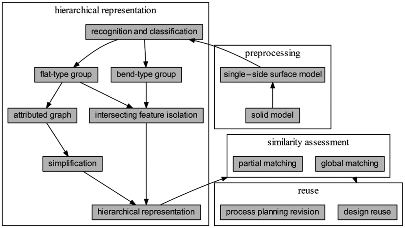
Proposed approach.
Hierarchical representation
Single-side surface model
Given a STEP-format solid model, a face-adjacent graph is first built to store face–edge topology.
The face-adjacent graph has been implemented in many geometric reasoning tasks, such as feature recognition 20 and model retrieval.3,4,24 While nodes in the face-adjacent graph represent faces, edges stand for their edge connections. In addition, information on faces and edges can be stored as properties of graph nodes and edges to facilitate reasoning. For example, by querying adjacent graph edges, face boundary edges are returned; adjacent face neighbours of a specific face are found using a graph algorithm. In each surface patch, the normal at a given point can be returned by the (u, v) parameter. Since sheet metal parts are relatively thin and surface normals on each side are continuous between boundaries, it is sufficient to use a single-side representation for geometric reasoning, see Figure 2. The process of its extraction is as follows.
Initialize an empty list
Sort areas of faces to select a face
Query the face-adjacent graph to find face neighbours
Append face neighbour
Repeat steps 3 and 4 for each face neighbour
Remove the face nodes from the face-adjacent graph with
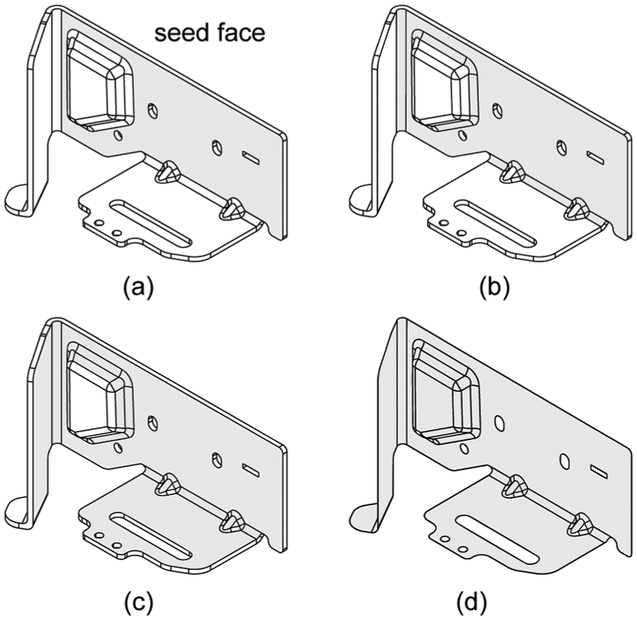
Single-side surface model of sheet metal part based on iterative seed growth. (a) sheet metal part with thickness t; (b) 1 step grown; (c) 2 steps grown; (d) converge, single side split
Flat–bend graph
The face types are classified into flat and bend. For every face in the face-adjacent graph, its face type is recognized by sampling points on faces and averaging curvatures, which follow the observation that the bending radius in sheet metal forming is generally
Flat-in-bend: the bent-type outer boundary edges of F are a subset of B’s boundary edges .
Bend-in-flat: the flat-type inner boundary edges of B intersect F’s boundary edges.
Flat-bend-adjacency: boundary edges of flat-type and bent-type faces intersect, but do not fit categories 1 and 2.
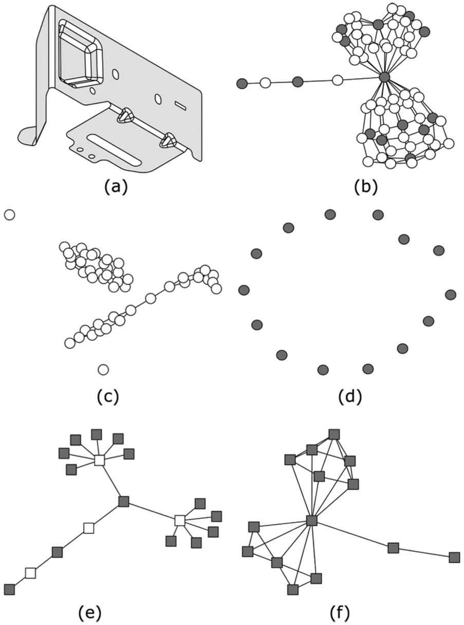
The undirected graph structure used for building flat–bend graphs and adjacent graphs. (a) single-side 3D model; (b) faceadjacent graph(FAG); (c) bent face graph(BG); (d) flat-face graph(FG); (e) flat–bend graph (FBG); (f) adjacent graph(AG).
These three morphological relationships describe whether F is inside B or not. They form the basis of the priority levels described later and suggest intersecting or compound features, which will be discussed later.
Attributed graph
The adjacent graph (Figure 3(f)) is an undirected graph, where the node is a flat group and an edge represents two flat groups
Input boundary edges of
For every input seed edge, query the face-adjacent graph to obtain the seed face f, where the seed edge belongs to the boundary edges of f.
Find the grown edge by following two rules: (1) the grown edge belongs to boundary edges of bent-type neighbours b of f, as determined by querying the face-adjacent graph; (2) the grown edge has no intersection points with the seed edge.
Update the seed face by the grown face; update the seed edge by the grown edge.
Repeat steps 3 and 4 until no new bent face is available.
Return ‘true’ if the grown edge intersects the
Restricted adjacency (1 and 2), single bend (top right) and compact bend (bottom right).
Simplification and assembly
Based on the adjacent graph, the simplification process is similar to mesh simplification. In each step, an edge is collapsed and a pair of nodes

Priority level used in simplification process.
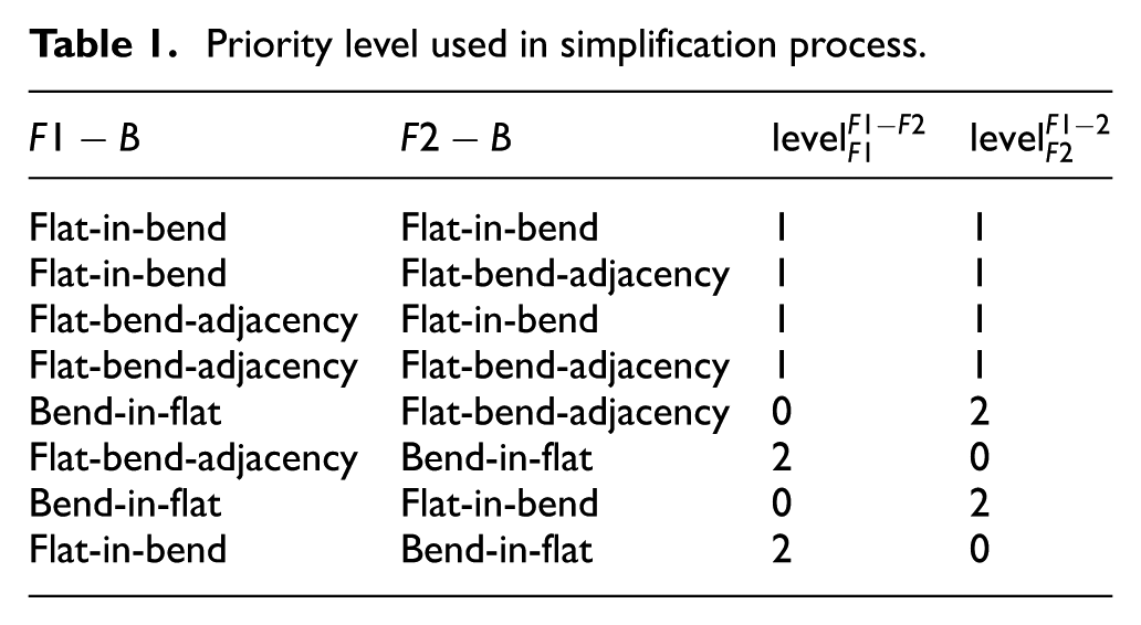
The sequential simplification algorithm of the adjacent graph is as follows.
Initial every node’s property ‘parent’ as ‘none’.
Select the maximum linked node in the adjacent graph as the initial
Select
Update the
Repeat steps 3 and 4 until the
Create new node
Add edges between
Broadcast ‘parent’ information to
Remove
Repeat step 2 to step 9 until the number of edges in the adjacent graph equals zero.
The simplification process and broadcasting algorithm in step 8 are illustrated in Figure 5. The demonstrative adjacent graph has six nodes and five edges (top-left solid line, Figure 5), with
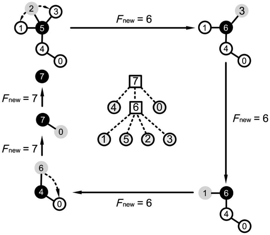
Simplification process, broadcasting algorithm and hypergraph.
Hierarchical graph
The hierarchical representation of the adjacent graph is a hypergraph composed of two components. One is the tree of resolution levels, a directed graph that organizes relationships between flat groups in multiple resolutions (centre of Figure 5). While ‘parent’ node 7 is the complete face set at resolution level 0, ‘child’ nodes 4–6–0 are decomposed subsets at resolution level 1. Since each resolution level is a different description of the same model, the leaf nodes that are not located at the largest depth should be included in multiple resolution levels, e.g., in resolution 2 there are nodes 4–1–5–2–3–0. Another component is the adjacent graph, which is a collection of undirected attributed graphs. It captures the adjacency between flat groups, which is referenced by the relative non-leaf nodes in the tree of resolution levels. For example, parent node 7 in the tree of resolution levels has three child nodes 4–6–0. The connected component of the adjacent graph (bottom left, Figure 5) is referenced by node 7 at the same time.
Intersecting feature, compound feature and holes
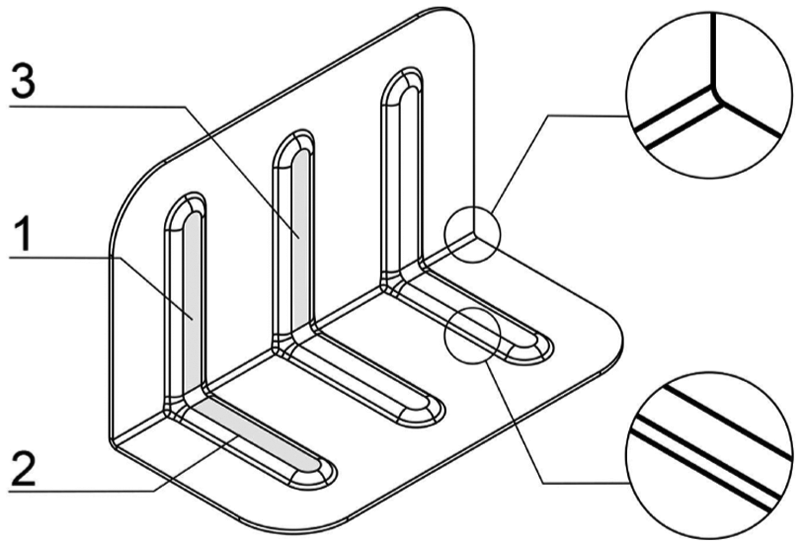
For the boundary-representation model, the connected edges of the face boundary are classified into inner and outer wires. While the orientation of the inner wire follows the clockwise direction, the outer wire follows the counterclockwise direction. In short, the surface material always lies on the left side of forward edges. 32 In this study, the inner wire, which is the inner boundary of the flat group, is defined with relation to feature detection and hierarchy construction, especially of the intersecting features, compound features and holes, see Figure 6.
Intersecting feature, compound feature and virtual faces.
Intersecting features, such as strengthen stiffeners, are commonly found in sheet metal parts, where flat groups are located in bending groups (see Figure 6). These intersecting features are of relatively small dimension yet dramatically change the topology of the whole part and its hierarchy. To preserve similarity consistency, the intersecting feature is isolated and is described in a subhierarchy before simplification of the adjacent graph. These flat groups should follow two conditions.
The flat group and its adjacent bend group follow the ‘flat-in-bend’ property in the flat–bend graph.
The outer boundary edges of these bend groups do not intersect the inner wire of any other flat group.
For multiple intersecting features along the bending group (see Figure 4), a higher-level hierarchy is built to group these subhierarchies. This is compatible with the pattern of features used in solid modelling and decreases the width of the hierarchy in higher-resolution levels, which would reduce the computation cost in the matching stage. After simplification and assembly of the adjacent graph, this hierarchy of intersecting features is attached to the same priority level as the adjacent flat groups.
Compound features are widely used, such as complex cover panels of mechanical equipment (see Figure 6). Based on the priority level discussed earlier, the bend group bounded by inner wires contributes a high priority level to its base flat group. This suggests a ‘parent–child’ relationship between the base flat group and compound features, which drives the hierarchy of compound feature in level of detail following the simplification strategy described earlier.
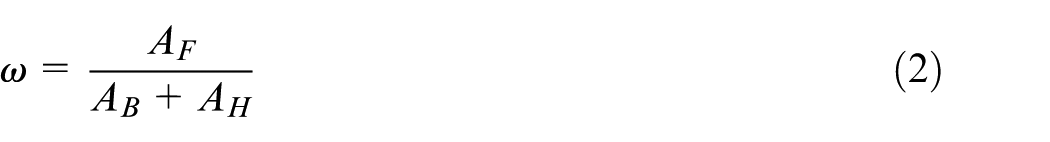
For the other inner boundaries that are not adjacent to additional faces, holes are detected. While the single-side surface model only takes face groups into account, the shape and distribution of holes at a detailed resolution level is missing. To address this issue, virtual faces covering holes are reconstructed from inner boundaries of base surfaces (Figure 6), so that every flat group node with hole F is further subdivided to a base node B and a node H for virtual hole faces. Because each resolution level is a proxy of a single-side surface model, the same total area should be shared, so that
Similarity assessment
Matching criteria
Given two hypergraphs, the matching process is initialized at their root nodes, which are matched by default. Then the adjacent graphs of root nodes are checked at the finer resolution level. In the adjacent graph, child nodes can be matched on condition that their parent nodes have been matched, which preserves the topology consistency discussed in previous research. 9 Before progressing to the next iteration, the best match with the largest similarity is selected because multiple scenarios of graph isomorphism may exist. We adopt a modified version of the VF2 algorithm 31 for subgraph isomorphism, where the matching condition is that the best match is of the largest total similarity, based on equation 4.
The time complexity of matching hypergraphs could be analysed approximately. Suppose that a pair of hypergraphs is fully matched. Each hypergraph is of a binary tree form and its tree of resolution levels has N leaf nodes. An N-leaf-nodes binary tree has
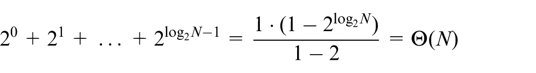
Compared with the binary tree, the greater the depth of a tree of resolution levels, the smaller the complexity for matching.
Similarity criteria
The area and geometric shape distributions of the matched hierarchy are used to calculate total similarity. Because the hypergraph describes the whole model at several resolution levels, each resolution level is a description of the similarity of two models. To summarize the total similarity,
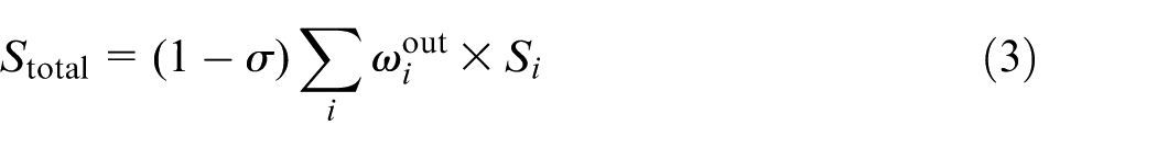
where
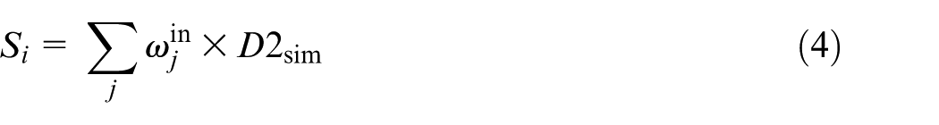
where
Implementation
While global retrieval finds similar sheet metal parts, single features or compact features are desired in partial retrieval. Based on the proposed hierarchical representation, these tasks can be realized in two forms. For global retrieval, the whole hypergraph from root to leaf nodes is indexed and stored in a repository. For partial cases, a subhierarchy of the hypergraph from a specific node to leaves is extracted. In this study, we adopted the proposal that the depth of the reusable part is greater than three. 10
Figure 7 illustrates the implemented prototype. It ran on an Intel i3 CPU, with 3 GB RAM and Windows7 x86. While PythonOCC
32
is used as a geometric kernel, the repository is collected from the National Design Repository,
33
GrabCAD
34
and our original data. As illustrated in Figure 7(a), the main frame is composed of a search key panel, an option panel and a repository browser. Figure 7(b) demonstrates the search result ranked by similarities. The hierarchy of the hypergraph can be plotted by selecting the model (e.g. ymg.stp, see Figure 7(c)). Each node of the tree of resolution levels in the top view is clickable and is linked by its adjacent graph on the bottom-left view and a
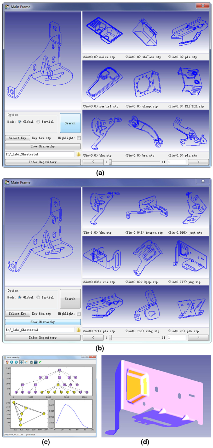
Prototype implementation, search result and hierarchy exploration of sheet metal part retrieval. (a) Main frame. (b) Search result. (c) Plot hierarchy. (d) Update 3D view.
To evaluate the performance of the proposed hypergraph approach, a precision–recall comparison is provided. The recall is the ratio between returned relevant models and all relevant models and the precision is the ratio between returned relevant models and all returned models. A returned model is defined as relevant if it is in the same category as the query model. Both precision and recall range from 0 to 1. If one precision–recall curve is above another curve, it is of better performance in retrieval. In the evaluation, 115 STEP203-format sheet metal parts from the National Design Repository 36 and our original data were classified in seven categories. The retrieval result is illustrated in Figure 8. While the D2 method 2 focuses on the geometric shape distribution, the face-adjacent graph approach 3 uses inexact matching to compare single-resolution topology based on face-adjacent graphs. The comparison result demonstrates that the proposed multiple-resolution method improves the retrieval effectiveness. This could be because the hypergraph approach combines advantages of both the D2 method and the face-adjacent graph in a hierarchical structure, which eliminates dissimilar partial features in different levels of detail.
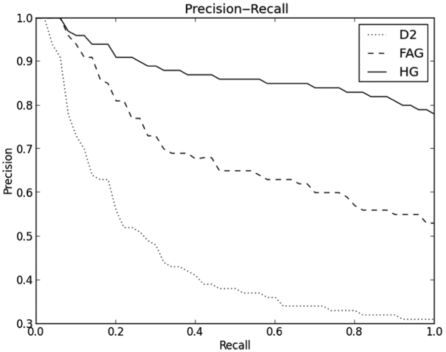
Precision–recall comparison between D2, face-adjacent graph (FAG) and hypergraph (HG).
Similar sheet metal parts support shape reuse and related manufacturing information revision. Figure 9 demonstrates the proposal. Global retrieval can be started from a simplified model (left); then the designer can browse and select a suitable model similar to the design intent (middle) with detailed features as a basis of modification. If designers want to add new features from other models in a relevant design context, partial retrieval can be launched by selecting subhierarchy as the search query (the extrusion on the middle model). Similar features of another model (compact features on Figure 6) can be copied, scaled and grafted to the variation design (right), which can be realized using direct modelling software independent of design history.
Left: less detailed model; centre: global reuse; right: partial reuse.
In product data management systems, much manufacturing information is stored along with the geometric shape, such as required machine tools and process planning involved. Finding similar parts or features by global or partial retrieval could therefore fetch related manufacturing information. At this stage, whether and how to adapt existing intrinsic knowledge of this manufacturing information to new cases still depends on domain experts. However, the system provides a hierarchical context for revision. The input sheet metal part can be compared both globally by whole models (hierarchy) and partially by decomposed features (subhierarchy), so that the related global manufacturing process and ‘process per feature’ can be returned for reference, assisting decision making for process planners.
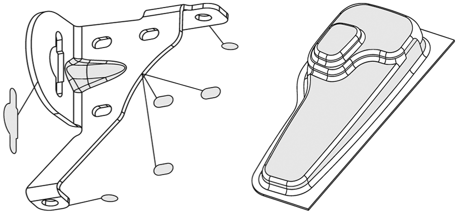
A geometric search prototype for mould base planning was implemented and integrated in an NX platform. In the automotive interior industry, plastic cover panels, such as car door panels, are mainly composed with a compound surface on one side and many detailed mounting features on the other side. Since the compound surface is similar to that of a sheet metal part, it can be extracted for retrieval. Figure 10 illustrates a search result in terms of extracted compound surface.
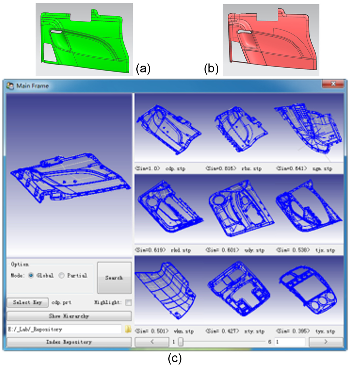
Similarity search of compound surface. (a) Compound surface of query model. (b) Compound surface of the best match. (c) Returned model ranked by similarity of compound surface.
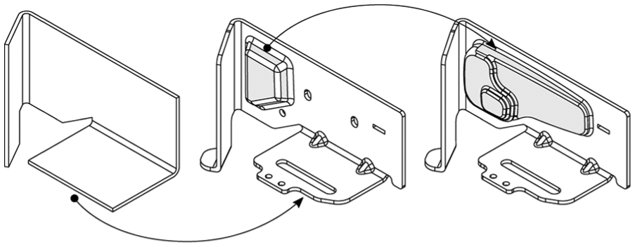
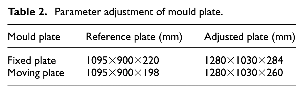
In mould design, the bounding box of a part is often used to design a core or cavity, which is related to the mould base plate size. Therefore, a similar compound surface is used to reuse similar mould bases. In Figure 11, the best match and its related mould base are used for reference and adaptation. First, the bounding box of the surface model is calculated. Then the ratio between the bounding box size and the fixed or moving plate size of the mould base are calculated to suggest the main parameters. The suggested and adjusted parameters are provided in Table 2. While the template of mould base driven by main parameters is prepared in advance, adjustment and improvement of the main parameters drives the update of the whole assembly.
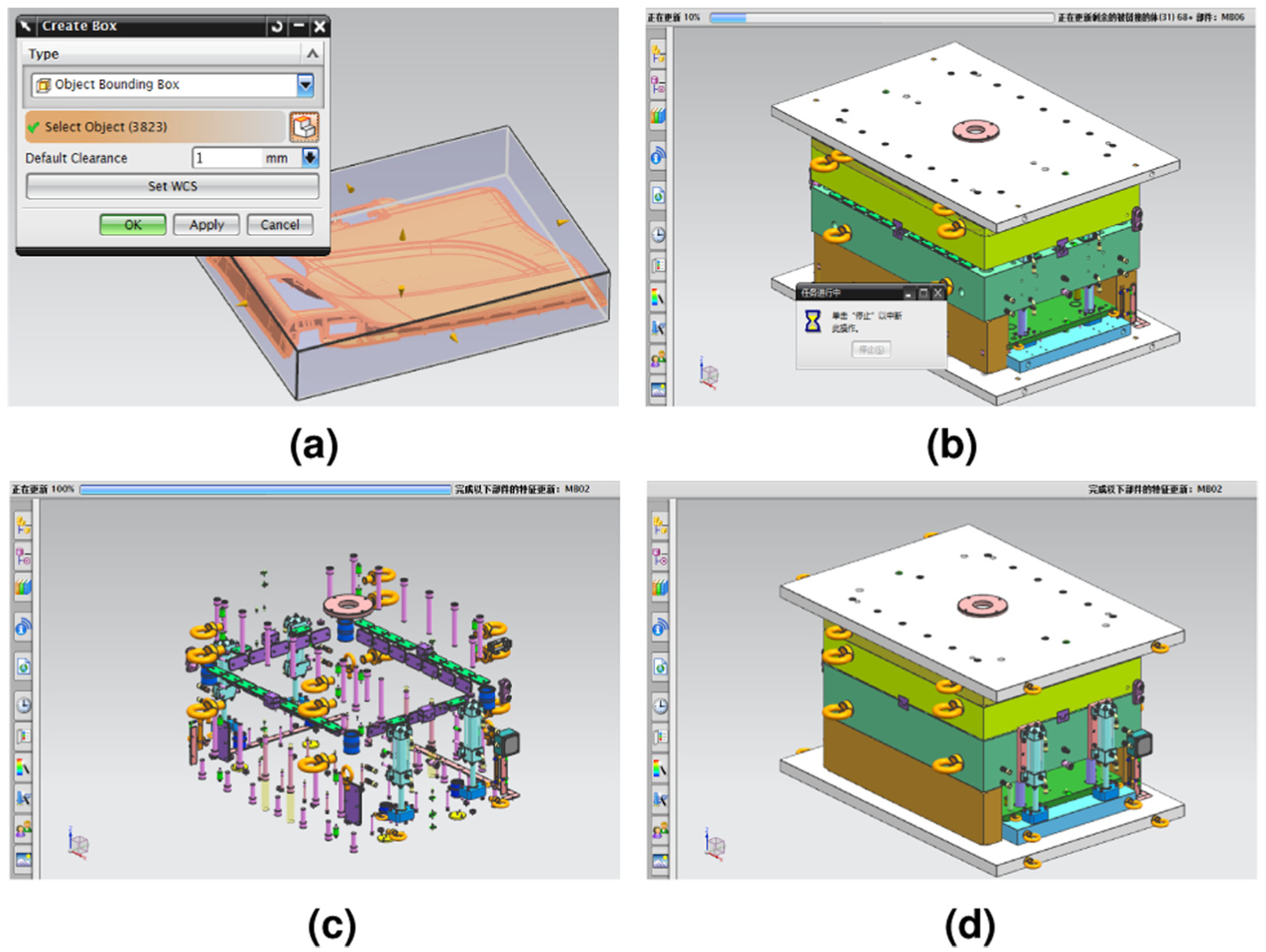
Parameter update of mould base. (a) Bounding box of door panel. (b)–(d) Mould base update based on adjusted parameters.
Parameter adjustment of mould plate.
Conclusions and discussion
We proposed a hierarchical representation and a similarity assessment algorithm for reuse of sheet metal parts. The hierarchy is of multiple resolutions, which support both global and partial retrieval. This approach is suitable for a neutral STEP format, which is supported by heterogeneous CAD or CAM systems. The hierarchical representation preserves both the geometry and topology of sheet metal parts, which makes it possible to further integrate manufacturing information. The implemented prototype system demonstrates possible applications in a manufacturing industry context, including design reuse and manufacturing process revision. This approach only works for a manifold boundary-representation model, which can be extracted from STEP-format files. For other native formats of commercial CAD platforms, such as NX, CATIA and Pro/E, the model can be converted to STEP, or it may be extracted by native API to build the hierarchy.
Some aspects could be studied in future. Firstly, this approach is limited in recognition of flat- and bent-type faces. It is not suitable for a single free-form surface model without bends; the construction of a hierarchical segmentation or abstraction for curvature distribution is an interesting topic. In addition, manufacturing knowledge representation and integration based on function mapping 37 or artificial intelligence is beneficial in improving the robustness of downstream applications, especially automatic decision making systems for process planning.
Footnotes
Acknowledgements
We thank Chuipin Kong for help with part of the implementation.
Declaration of conflicting interests
The author(s) declared no potential conflicts of interest with respect to the research, authorship, and/or publication of this article.
Funding
The author(s) disclosed receipt of the following financial support for the research, authorship, and/or publication of this article: This work was supported by the National Science Foundation of China (Grant No. 60903111).