
Abstract
The 080A15 and 30CrMnMo steels were cut by precision sawing machine. The microscopic characteristic of the chip surface and the chip failure microscopic mechanism have been studied. The studies show that the formation of saw-tooth chip is mainly a function of the strength and thermal conductivity. For 080A15 steel, the strength is low and the thermal conductivity is high, the plastic work was absorbed continuously by the process of plastic deformation, and the heat was dissipated at any moment. The heat energy did not reach the critical value causing thermal softening. The chip is more prone to ductile fracture. For 30CrMnMo steel, the bonding ability is stronger among atoms, and thermal conductivity is smaller. The plastic deformation is extremely fast and the instantaneous temperature rise was very high because the heat energy reached the critical value causing thermal softening. Therefore, the chip is more prone to adiabatic shear failure to form the saw-tooth chip divided uniformly by adiabatic shear band. The research results help to provide the basis for selecting materials with different adiabatic shearing sensitivities in the process of high-speed cutting by studying the energy barrier on the influence of chip failure mechanism.
Introduction
High-speed cutting technology represents the cutting edge in machining at present.1,2 That instantaneous impact with high velocity between workpiece and tool during the high-speed cutting process causes shear failure to limit a small region, produces a transient temperature rise sharply in the local area, and results in thermal softening effect to form adiabatic shear band (ASB). The old cutting theory is no longer applicable during the extreme processing conditions.
The saw-tooth chip is prone to producing in high-speed cutting. Its formation mechanism and affecting factors are far from fully understood due to the difficulty of online detection. 3
The saw-tooth chips can accelerate tool wear, reduce the surface quality, and produce a high-frequency vibration of cutting force. 4 Therefore, it is important to study the saw-tooth chip failure mechanism.
At present, there are two main theoretical systems summarized about the formation mechanism of saw-tooth chip. One is periodic crack theory, and the other is adiabatic shear theory. The periodic crack theory says that periodical crack initiated on the free surface of workpiece and further propagated in the primary deformation zone results in the formation of saw-tooth chip.5–7
The adiabatic shear theory says that the formation of saw-tooth chips results from the catastrophic thermoplastic shear caused by ASB in the primary deformation zone. This theory is generally accepted as the explanation of saw-tooth chip formation.8–10
ASB formed by the coupling effect of thermal softening, strain, and strain rate hardening is a kind of deformation localization narrow band. It often means the harbinger of material failure. 11 ASB can be divided into two main types―phase transformed ASB often causing micro-structural changes and deformed ASB with no organizational change. The researches show that the micro-structural changes in ASB include dynamic recrystallization, dislocation, phase transformation, and amorphization.12,13
Many studies on formation mechanism of saw-tooth chip based on the adiabatic shear theory have been done so far. Bhuiyann et al., 14 Özel and Ulutan, 15 Xu et al., 16 and Gao et al. 17 analyzed the effect of cutting parameters on the formation of the saw-tooth chip through observing chip metallographic graph. They have found that the rake angle and cutting speed significantly influence the chip morphology. The ASB leads to the saw-tooth chip with increasing the cutting speed, but the chip morphology could be controlled by the optimization of a combination of cutting speed, feed per tooth, and cutting depth. 18 The effects of the cutting speed and the hardness of workpiece on chip formation are interdependent. 19
Wang, 20 Wang et al., 21 and Wan et al. 22 carried out a research on the microscopic structure of the adiabatic band in the saw-tooth chip. The formation mechanism of saw-tooth chip depends on the adiabatic shear sensitivity of workpiece materials. The deformed band changes into transformed band with the increase in cutting speed during the evolution of microstructure inside the ASB.
Calamaz et al., 23 Mohammad and Tuğrul, 24 and Obikawa and Usui 25 studied the effect of constitutive relation and material characteristics (strain softening, thermal softening, etc.) on the formation of saw-tooth chip through finite element analysis.
It is reported by Bhuiyann et al., 14 Gao et al., 17 and Simoneau et al. 26 that due to the heat resulting from the intense friction, stick-slip friction depending upon the material microstructure at the tool–chip interface plays an important role in the chip formation process.
The above studies on the formation mechanism of saw-tooth chip have focused mostly on the cutting parameters, microscopic structure and evolution inside the ASB, numerical simulation methods, stick-slip friction, and the effect of properties of workpiece materials, but there are few literatures to analyze comprehensively the effect of material property parameters and alloy element on the formation mechanism of saw-tooth chip. In this article, the effect was studied from the view of energy.
Research results of the failure characteristics of saw-tooth chip have important implications to choose and design suitable material or control the chip type for high-speed cutting.
Experimental procedures
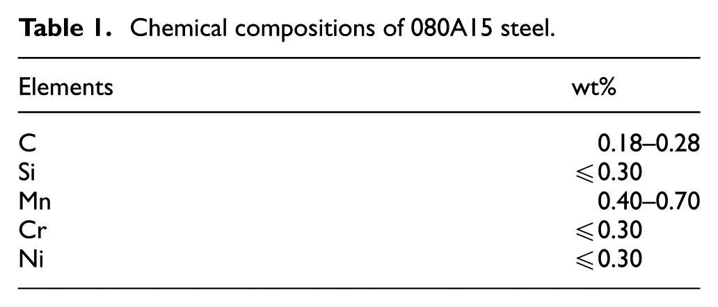
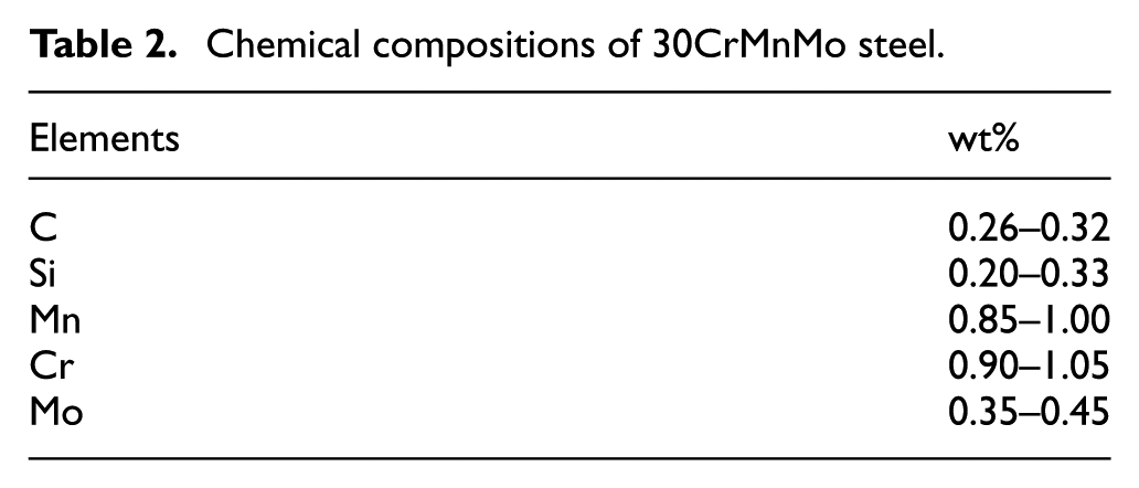
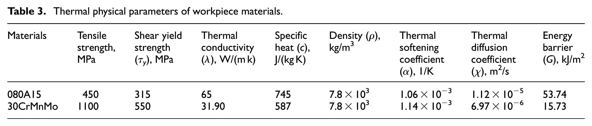
Two workpiece materials of 080A15 and 30CrMnMo steels are used in this study. The workpieces are 20 mm in diameter. The cutting experiments were conducted on high-speed precision sawing machine whose cutting speed is 3100–13,800 m/min. The saw blade has 80 teeth. It is 200 mm in diameter. The microstructure of metallographic specimen made by chip was observed with scanning electron microscope and metallographic microscope. The chemical compositions of 080A15 and 30CrMnMo steels are listed in Tables 1 and 2, respectively. The thermal physical parameters are listed in Table 3.27,28
Chemical compositions of 080A15 steel.
Chemical compositions of 30CrMnMo steel.
Thermal physical parameters of workpiece materials.
Experimental results and discussion
Microscopic characteristics of chip surface
The original microstructure of 080A15 steel is shown in Figure 1. The microstructure of 080A15 steel chip changed with cutting speed. The grain breaking occurred under the action of cutting force at the speed of 52 m/s, as shown in Figure 2(a). The grain breaking, deforming, and sliding became more serious with the increase in cutting speed, which result in many discontinuous stripes and grooves on the surface of chip. The tread of the stripes is along the direction of grain deformation. The stripes usually pass through the grain boundary. It indicates that 080A15 steel shows good plastic liquidity at the speed of 147 m/s, as shown in Figure 2(b).
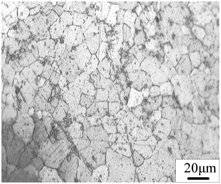
The original microstructure of 080A15 steel.
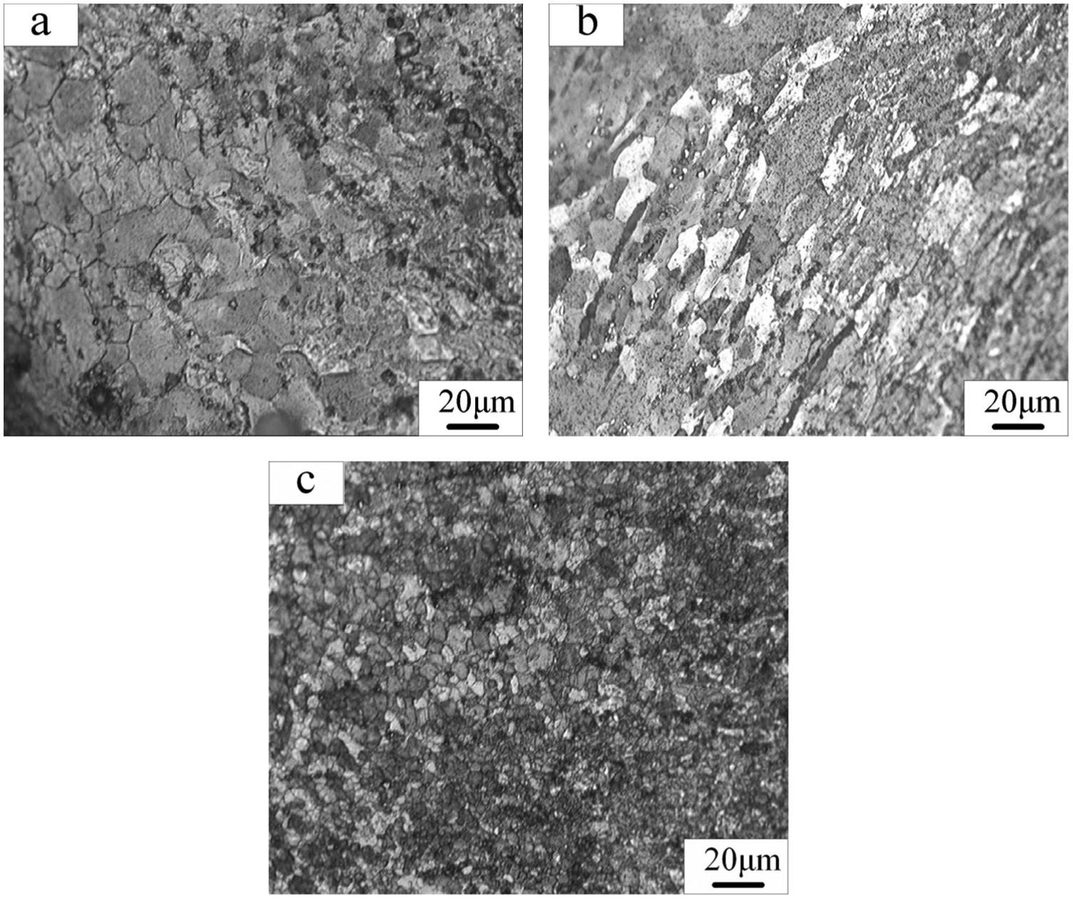
The microstructure of 080A15 steel chips at different speeds: (a) grain breaking (v = 52 m/s), (b) grain deforming (v = 147 m/s), and (c) grain recrystallization (v = 210 m/s).
The slip deformation layer was created in chip in the cutting process, and with the increase in cutting speed, the recrystallization refinement was caused to form the recrystallized layer in which the grains became more dense and fine at the speed of 210 m/s, as shown in Figure 2(c).
Therefore, the major deformation and failure mechanisms of 080A15 steel chip are grain breaking, glide, and dynamic recrystallization, and there is no ASB.
However, the broad deformed ASB in which the structure did not change and grains become more uniform and dense was observed using scanning electron microscope for 30CrMnMo steel chip when the speed is only 52 m/s. The microstructure is densest at the center of the ASB. The deformation is serious on both sides of the deformed ASB, but the deformation became small and the grains became coarse gradually along the sides outward, as shown in Figure 3(a). The black tiny phase transformed ASB was observed at the speed of 147 m/s. The deformation surrounding the ASB, inside which recrystallization occurred and the original microstructure cannot be distinguished, is streamlined, as shown in Figure 3(b).
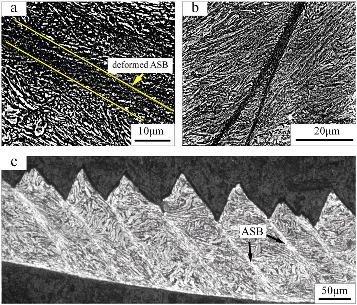
The ASB microstructure in the 30CrMnMo steel chips: (a) the deformed ASB (v = 52 m/s), (b) the transformed ASB (v = 147 m/s), and (c) the saw-tooth chip morphology.
The saw-tooth chips evenly spaced by ASBs were formed, as shown in Figure 3(c). The chip is prone to breakage along the ASB. Therefore, the major deformation and breaking mechanism of 30CrMnMo steel chip is adiabatic shear failure.
The formation of ASB and the influence factors
For ductile materials, the accumulated plastic work resulting from strong plastic deformation in primary deformation zone continues to grow with the increase in cutting speed in the plane strain state of orthogonal cutting. The plastic work is converted constantly into heat energy, the temperature rises gradually, and the softening phenomenon occurs. When the heat energy causing thermal softening surpasses the accumulated plastic work originating from strain hardening and strain rate hardening, the energy barrier resulting from the accumulated plastic work is overcome along the shear direction in the local area of primary deformation zone, namely, the ASBs occur.
The smaller the energy barrier needed to overcome in primary deformation zone, the easier the occurrence of ASB. On the contrary, the occurrence of ASB is more difficult.
The equation of energy barrier was given by Crady 29
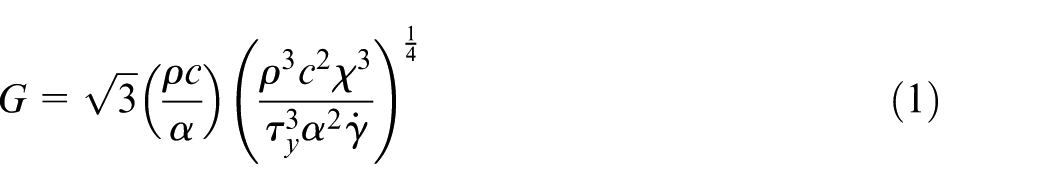

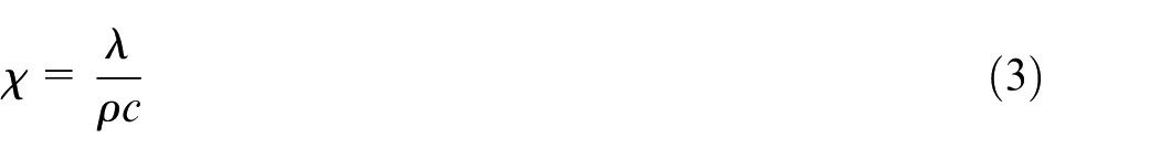
where
The temperatures of complete austenitizing for 080A15 and 30CrMnMo steels are about 940 °C and 880 °C, respectively. When the material is completely austenitized, assuming
The smaller the G value, the smaller the critical heat energy needed to produce thermal softening, namely, the smaller the energy needed to produce ASB, the stronger the adiabatic shearing sensitivity that means the ease or difficulty of forming ASB.
The energy barrier can measure the size of the adiabatic shearing sensitivity by equation (1) with specific heat, thermal softening coefficient, density, thermal conductivity, and strain rate.
The strain rate is equal under the same cutting condition. Let the strain rate
The adiabatic shearing sensitivity of 30CrMnMo steel is far more than 080A15 steel because the size of the adiabatic shearing sensitivity is in inverse proportion to the value of accumulated energy needed to produce the adiabatic shearing phenomena.
The ASBs were formed in the 30CrMnMo steel chip, and there were no any ASBs in the 080A15 steel chip under the same cutting condition. The test results are consistent with the calculation results.
The factors affecting the deformation localization of adiabatic shear are strength, thermal conductivity, thermal softening coefficient, density, specific heat, and strain rate by equation (1). The difference of the density or specific heat is smaller for general steel materials, and their softening coefficients are also close because of their approximate melting points. The strain rate is equivalent under the same experiment conditions. But the difference of the thermal conductivity or strength much affected by compositions and microstructures is usually very big. Thus, the main factors affecting the adiabatic shear failure are thermal conductivity and strength. The stronger the material strength, or the smaller the thermal conductivity, the easier the occurrence of ASB as well.
The formation mechanism of saw-tooth chip
The experimental results of the above two kinds of materials in the same experimental conditions are obviously different. The difference between the 080A15 and 30CrMnMo steels mainly results from the different strengthening phase. 080A15 steel is supersaturated interstitial solid solution that C is in α-Fe. The Fe–C crystal cell in 080A15 steel is shown in Figure 4. The strengthening phase in the 080A15 steel is mainly C–Fe bond combination. When the alloy atom Me (Cr, Mn, and Mo) dissolves into Fe–C, the alloy atoms occupy the position of Fef atoms to form the substitution solid solution Fe–C–Me cell, 30 as shown in Figure 5, so there are the stronger C–Me bond combinations (including C–Mo, C–Mn, and C–Cr) in the strengthening phase of 30CrMnMo steel besides the C–Fe bond combination.
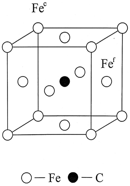
The crystal cell of Fe–C in 080A15.
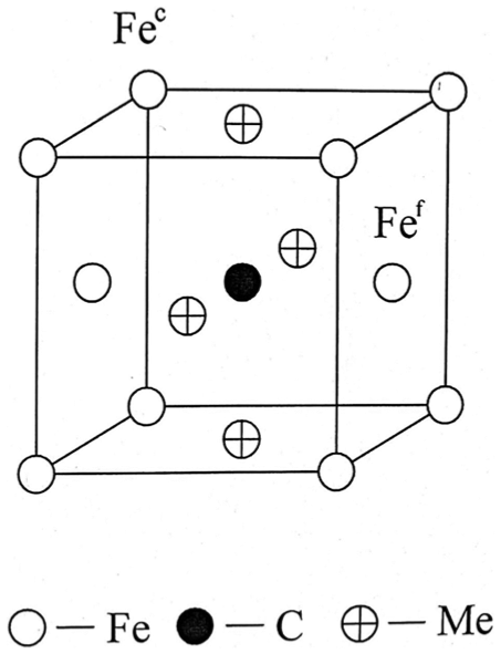
The crystal cell of Fe–C–Me in 30CrMnMo.
The position of solute atoms located in the lattice system will present a short-range order distribution with certain rules when binding force between different atoms (AB) is bigger than that between the same atoms (AA) or (BB) according to the micro-inhomogeneity theory of solid solution. Therefore, C atom and the surrounding different atoms constitute the hard octahedrons due to the bigger binding force, and the stronger –C–Me–C–Me– bond nets are formed resulting from the more bigger binding force between Me and C atoms, namely, the showing of the short-range order distribution of atoms, as shown in Figure 6.
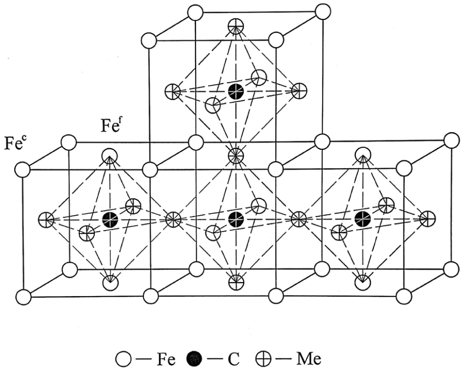
The sketch of Fe–C–Me segregation.
The short-range order distribution of atoms is just C–Me segregation that hinders the dislocation movement in solid alloy. 31
The phase transformation of alloys is the process of the old covalent bond rupture and the new covalent bond formation. The covalent bond formed between atoms in solids is the skeleton which constitutes the entire unit cell. Therefore, the more difficult the rupture of covalent bond, the more powerful the phase transformation resistance and the higher the strength.
The C–Me segregation with strong binding force happens because there are always two Me atoms near a C atom and two C atoms near a Me atom in the same way (Figure 6). Thus, the unit cells possessing C atoms and Me atoms are connected to each other by this way to form a short-range ordered C–Me enrichment region that hinders dislocation motion in the local area in 30CrMnMo steel. Therefore, the action force destroying the 30CrMnMo steel is much bigger than that destroying 080A15 steel.
Therefore, it can be considered that the C atom is bound incrementally by the surrounding atoms, and the phase transformation is difficult in the structural units containing carbon and alloy elements, so that the resistance to dislocation motion, the stability, and the strength of the alloy steel are all increased. Just as mentioned above, the tensile strength of 080A15 and 30CrMnMo steels is 450 and 1100 MPa, respectively (Table 3).
The slip resulting from the dislocation motion occurs when the part of crystal slides along a certain crystallographic direction on the crystallographic plane under the action of shear stress
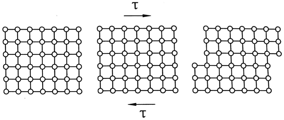
Slip caused by dislocation motion.
The crystal grains arrangement in the workpiece material is shown in Figure 8(a). The crystal grains become oval at the beginning under the action of cutting force F, then they are elongated gradually along the long-axis direction, but the direction of the long axis is always perpendicular to the direction of the external force, as shown in Figure 8(b).
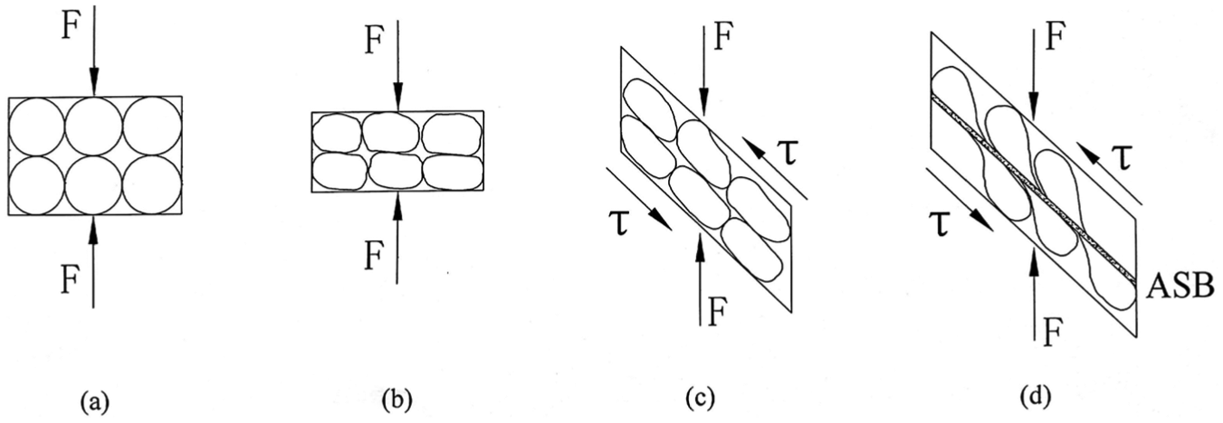
The schematic diagram of plastic deformation: (a) The original arrangement of the crystal grains, (b) The elongated crystal grains under the action of cutting force, (c) The plastic deformation resulting from sliding of the slip system, (d) The formation of ASB.
Sliding of the slip system results in plastic deformation when the shear stress reaches a critical value along the direction of maximum shear stress, namely, slip direction within a certain slip plane, as shown in Figure 8(c).
When 080A15 steel was cut, the shear stress along the slip direction and the crystal slippage along every slip plane are all smaller, and the plasticity is high because of the weak binding force between atoms and the smaller acting force that is created when the C–Fe bond was destroyed. The plastic deformation is shown in Figure 8(c), which is as shown in Figure 2(b). The plastic work was absorbed continuously by the process of the tearing, stripes sliding, and grain crushing on the surface of the chip, and the heat was dissipated at any moment because of the larger thermal conductivity and the better heat conduction performance.
The critical heat energy cannot be reached to produce ASB because the plastic work accumulated before thermal softening is released constantly. Therefore, it was difficult for the 080A15 steel to produce thermal softening phenomenon not to form the ASB. Thus, the chip was damaged by ductile fracture. The grains deformation is uniform under the action of cutting force F. The schematic diagram of the process of the cutting deformation is shown in Figure 9.
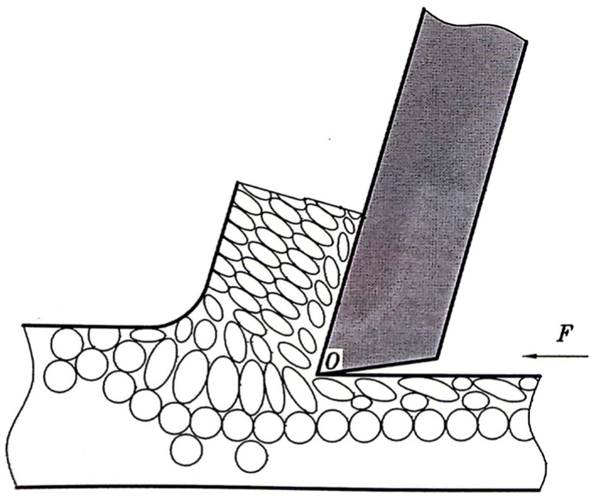
The schematic diagram of cutting 080A15 steel.
When 30CrMnMo steel was cut, because the bonding force of Me–C structural unit is stronger than that of C–Fe structural unit in 080A15 steel, the kinetic energy needed to destroy these structural units was very big. And the C–Me enrichment region of the short-range order was an obstacle to dislocation motion to form the dislocation pile-up group with a great stress concentration in the process of deformation. Therefore, the shear stress along the slip direction and the crystal slippage was large while the C–Me bond was destroyed in an instant, and the accumulated plastic work was very high, and the thermal conductivity is low. Thus, that the large amount of heat coming from the plastic flow was too late to spread and the instantaneous temperature rise was very high made local thermal softening phenomenon to form ASBs, as shown in Figure 8(d), just as Figure 3(b), namely, the critical heat energy needed to produce thermal softening can be reached and the thermal softening exceeds the strain hardening. After producing ASBs, the surrounding deformation energy was released in an instant, the deformation near the ASB was coordinated, and no further adiabatic shear deformation would be formed in a certain area around the ASB temporarily. But the plastic work continued to accumulate and then the next ASB would occur by repeating the above process. Therefore, the ASBs were distributed sparsely to form the saw-tooth chip with uniform spacing of ASBs, as shown in Figure 3(c). The schematic diagram of the cutting process is shown in Figure 10.
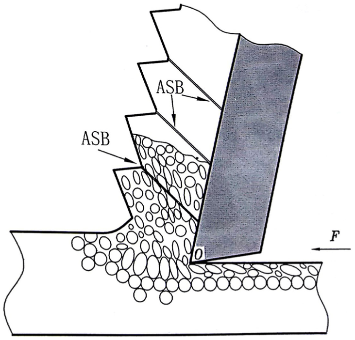
The schematic diagram of cutting 30CrMnMo steel.
Carbon steel and alloy steel formed by the addition of some alloying elements in carbon steel are commonly used in industry. Therefore, it is necessary to study the influence of specific alloying elements on cutting performance. Previous studies show that saw-tooth chips evenly spaced by ASBs can occur in many materials, such as titanium alloy, nickel-based alloy, Ni–Fe super alloy, and hardened steel, during the process of high-speed milling, high-speed grinding, and high-speed cutting,17,18,22,32–38 but the chip microcosmic characters of 080A15 steel belonging to carbon steel and 30CrMnMo steel belonging to alloy steel are very different; the main reasons are due to different alloying elements.
To sum up, chip failure mechanism is mainly a function of the strength and thermal conductivity. The research results are helpful to provide the basis for selecting materials with different adiabatic shearing sensitivities in the process of high-speed cutting.
Conclusion
For 080A15 steel, the shear stress along the slip direction is small and the plasticity is good. The heat was dissipated at any moment because of the larger thermal conductivity and the better heat conduction performance. It was difficult to produce thermal softening phenomenon not to form the ASB. The chip was damaged by ductile fracture.
For 30CrMnMo steel, the strength is high, and the plastic deformation is very rapid. The instantaneous temperature rise is very high because of the lower thermal conductivity, so a lot of heat cannot send out in time to produce the saw-tooth chip with the adiabatic shear failure.
Chip failure mechanism is a main function of the strength and thermal conductivity. The research results are helpful to provide the basis for selecting materials with different adiabatic shearing sensitivities in the process of high-speed cutting.
Footnotes
Declaration of conflicting interests
The author(s) declared no potential conflicts of interest with respect to the research, authorship, and/or publication of this article.
Funding
The author(s) disclosed receipt of the following financial support for the research, authorship, and/or publication of this article: This work is financially supported by the National Natural Science Foundation of China (Grant No. 51275317/E050901) and Open Fund of Key Laboratory of Liaoning Province for Advanced Manufacturing Technology and Equipment, Shenyang Ligong University.