
Abstract
Taguchi’s L9 orthogonal array has been effectively used to study the effect of process parameters such as voltage, feed rate and electrolyte concentration on material removal rate in context of two different types of electrolyte, namely, aqueous NaCl solution and CuSO4 mixed aqueous NaCl solution. The results indicated that Cu2+ ions formed due to electrochemical reactions prevent the oxidation of Fe2+ to Fe3+ and catalyze the anodic dissolution of iron during machining. The experimental results were analyzed using analysis of variance method to investigate the significance and percentage contribution of individual process parameters on performance characteristics.
Introduction
Electrochemical machining (ECM) has got an industrial importance due to its capability of controlled atomic level metal removal. 1 It is an anodic dissolution process based on electrolysis, where the application of a more traditional process is not convenient. ECM has been successfully employed in aerospace, automobile industries and now gaining much importance in the electronics and other high-tech industries for the fabrication of micro-components.2,3 Mask-less and through-mask electrochemical micromachining techniques have been successively used in thin films and foils of materials that are difficult to machine by other methods.4,5 ECM is a low-voltage (5–25 V) machining process which offers high metal removal rate and also capable of machining hard conductive materials into complicated profiles without any thermal damages, thus suitable for mass production work with low labor requirements.6,7 The dissolution rate is highly reliant on the selection of electrolytes and its current-carrying capacity. On increasing the concentration of electrolyte solution, dissolution rate also increases, but excess concentration allows the crystal formation, which may damage the accessories of ECM and reduce the volume of electrolyte in flow pipes. The conductivity of electrolyte depends not only on the concentration but also on the ionic interaction. Thus, the current-carrying process done by the base electrolyte is small, but H+ and OH− ions produced in electrolysis of water play an important role.8,9 The achievement of higher dissolution rate in ECM is a strong research base which is possible with a change in the composition of electrolyte solution to promote catalytic effect during dissolution. 10
During ECM of iron at low current density, it has been observed that Fe+ cation formed very easily, but it is highly unstable and immediately oxidizes into Fe2+ state. Increase in current density leads to simultaneous production of Fe2+ and Fe3+, and at higher current density, the apparent valence of iron increases above three. 11 Therefore, stabilizing Fe2+ in the aqueous solution is a challenge during dissolution.
Experimental details
Experimental setup and principle of ECM
The experimental setup of ECM is shown in Figure 1
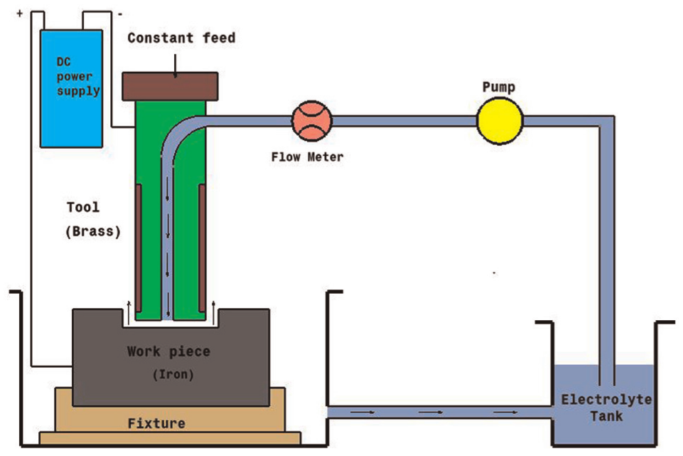
Experimental setup.
ECM is an anodic dissolution process that works on the principle of Faraday’s law. During machining of iron in the presence of aqueous NaCl electrolyte solution, the following chemical reactions are observed. 12
Reactions at cathode


It shows that only hydrogen gas will evolve at cathode.
When pure iron is being machined electrochemically, the following reactions would occur13,14


It shows that during ECM of iron in NaCl electrolyte, iron is removed as Fe(OH)2 and precipitated as sludge, while sodium chloride is recovered back. Due to further reactions, formation of Fe(OH)3 takes place and hence, it is confirm that iron exist in Fe2+ and Fe3+ states during dissolution.
Determination of Fe2+ and Fe3+ ions in electrolyte solution
The electrolyte solution containing Fe2+ and Fe3+ ions was collected. Fe2+ ions were determined directly by titrating a known volume of iron electrolyte solution with K2Cr2O7 in acidic medium (HCl)

Internal indicator N-phenyl anthranilic acid was used to mark the end point. Fe3+ ions were determined after all of them are reduced into Fe2+ ions with SnCl2 in the presence of hot HCl

The solution was then cooled and the excess SnCl2 was removed by adding HgCl2 solution

Titration of known volume of standard solution was done using standard solution of K2Cr2O7 in acidic medium. From the volume of K2Cr2O7 used, the total amount of Fe2+ and Fe3+ ions was determined. The amount of Fe3+ ions was determined by subtracting the amount of Fe2+ which is determined earlier.
Material removal rate (MRR) during ECM is greatly influenced by dissolution valence. As the dissolution valence decreases, MRR increases. In this article, an approach is made to enhance the electrochemical dissolution of iron through control of valency (transition); therefore, in this direction, the use of CuSO4 mixed aqueous NaCl electrolyte solution is suggested which dissociates further to form Cu2+ on passing electric current through the circuit.
The dissolution limit of iron by Cu2+ ions can be justified by considering the standard electron potential E° for Cu2+, Fe/Fe2+ and Fe/Fe3+ described as follows 15


As E° for Cu2+ → Cu is more positive than Fe2+ → Fe, Cu2+ will oxidize Fe to Fe2+. However, as E° for Cu2+ → Cu is less positive than Fe3+ → Fe2+, Cu2+ will not oxidize Fe2+ to Fe3+.
Electrolyte solution
The results of electrical conductance of NaCl at different concentrations in water are shown in Figure 2. The concentration of 20 g (0.5 M) of NaCl/L of water was taken as the optimum concentration to test the concentration requirement of CuSO4. Conductance was measured for different concentrations of CuSO4 in selected concentration of NaCl in water. As shown in Figure 3, at 0.8 g of CuSO4 per 100 mL of aqueous NaCl, PH value is adequate to promote the dissolution of iron. Mixing of CuSO4 with the aqueous NaCl gives the saturated solution of Na2SO4 and CuCl2. As the potential difference is applied between the workpiece and the tool, CuCl2 further dissociates to form Cu2+ ions.
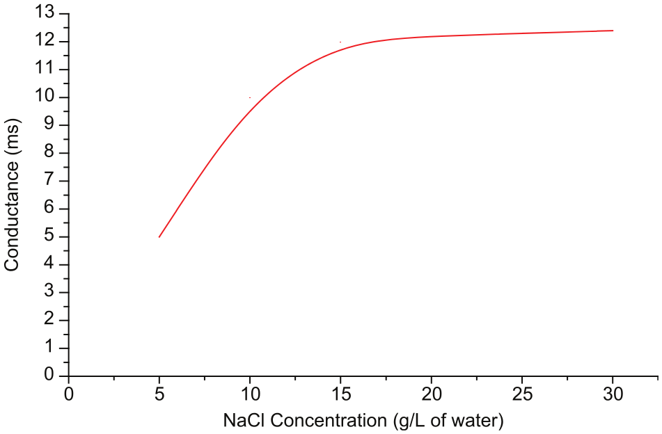
Conductance versus NaCl concentration.
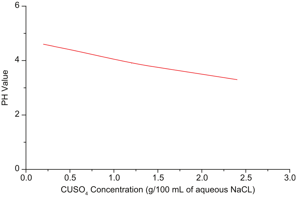
PH versus CuSO4 concentration (g per 100 mL of aqueous NaCl).
Machining conditions
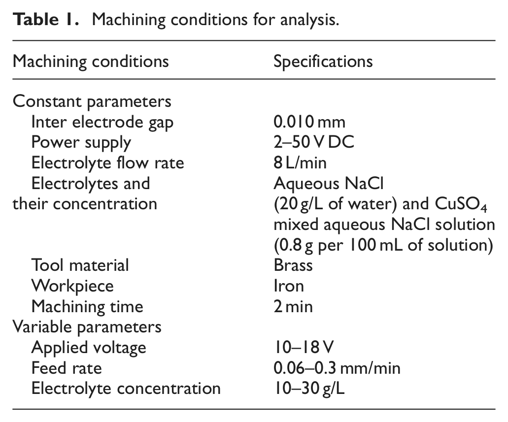
The selected machining parameters on the basis of performance characteristics are shown in Table 1.
Machining conditions for analysis.
Selection of machining process parameters
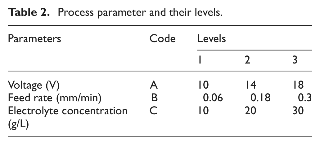
Table 2 shows the machining parameters and selected levels for experimental procedure.
Process parameter and their levels.
Measurement of MRR
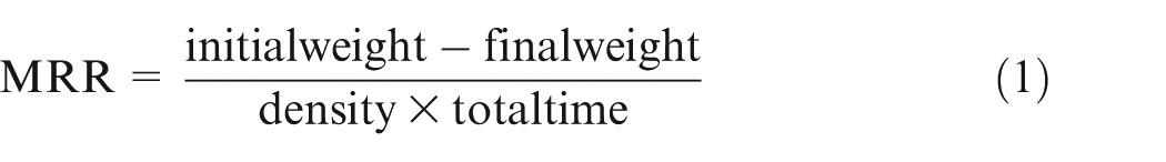
The initial weight of the workpiece was taken for calculation of MRR. Keeping the flow rate constant at 8 L/min, the rest of the parameters are set according to Table 1 for each run. Workpiece was kept horizontal, and a cylindrical electrode was used for machining. Gap between the tool and the workpiece was maintained carefully to avoid choking. The electrode was fed continuously toward the workpiece during machining and time was recorded. After machining, cavity was formed on the workpiece. The final weight of the workpiece was taken, and MRR was calculated as per the following formula
Experimental work
The design resulted in a total of 18 experiments, which are performed at a supply voltage of 10–18 V, 10–30 g/L of electrolyte concentration and 0.06–0.3 mm/min feed rate as the values for the control variables. The responses measured are the MRR. Scheme of the experiments is shown in Table 3.
Taguchi’s L9 orthogonal array for MRR.
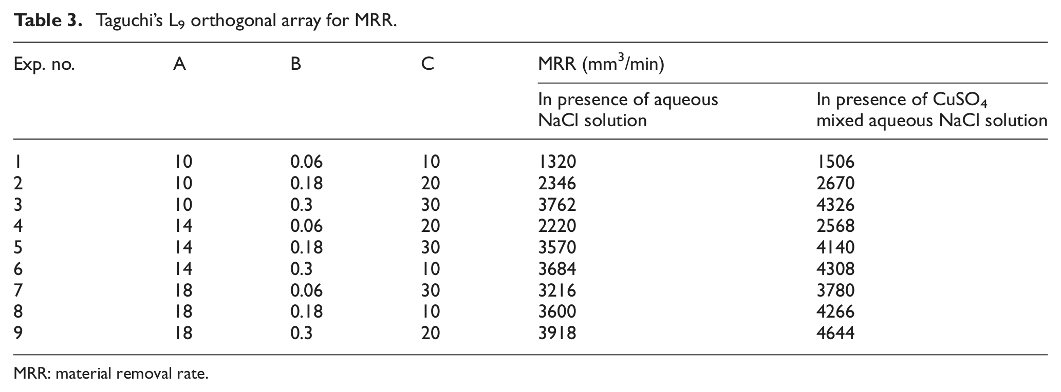
MRR: material removal rate.
Results and discussion
Analysis of variance when machining in the presence of NaCl electrolyte solution
The analysis of variance (ANOVA) has been performed to determine the significance and percentage contribution of individual process parameter on MRR during machining of iron in aqueous NaCl solution. F-test presented in Table 4 assesses that the most significant factors contributing toward the MRR are the feed rate and the voltage with percentage contribution of 55 % and 28.3 %, respectively. Graphical representation of percentage contribution of each parameter is shown in Figure 4.
ANOVA for MRR (NaCl solution as electrolyte).
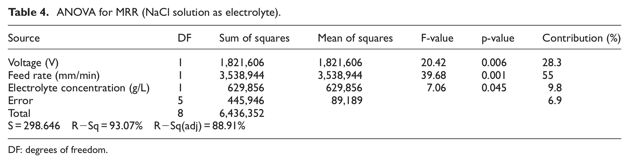
DF: degrees of freedom.
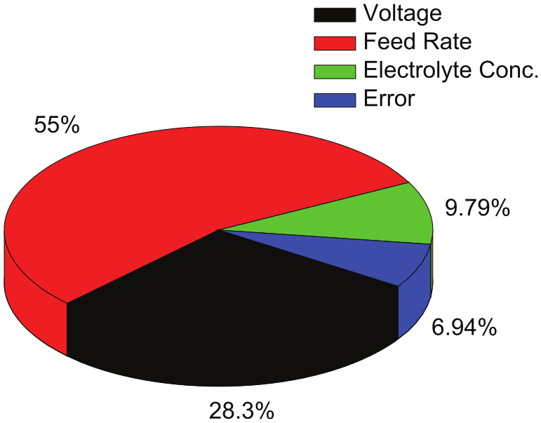
Contribution of the parameters (aqueous NaCl as electrolyte).
Figure 5 shows the main effect plot of the MRR depicting the effect of various machining parameters on MRR while machining in the presence of aqueous NaCl solution. As seen from the plot obtained, the MRR increased with increase in both voltage and feed rate. This is due to the fact that with increase in voltage, the current increases in the inter electrode gap, thus increasing the MRR. Feed rate is another important parameter. Increase in feed rate results in decrease in the conducting path between the workpiece and the tool resulting in high current density, thus enhancing the rapid anodic dissolution. Although the higher concentration of NaCl is favorable for better MRR, the larger number of ions associated during the machining process increases the machining current, but excess concentration allows the crystal formation which reduces the volume of electrolyte in flow pipes and also affects the dissolution rate. ECM of iron in the presence of NaCl electrolyte promotes the oxidation of Fe2+ to Fe3+. The maximum MRR obtained during machining of iron in aqueous NaCl solution recorded was 3918 mm3/min.
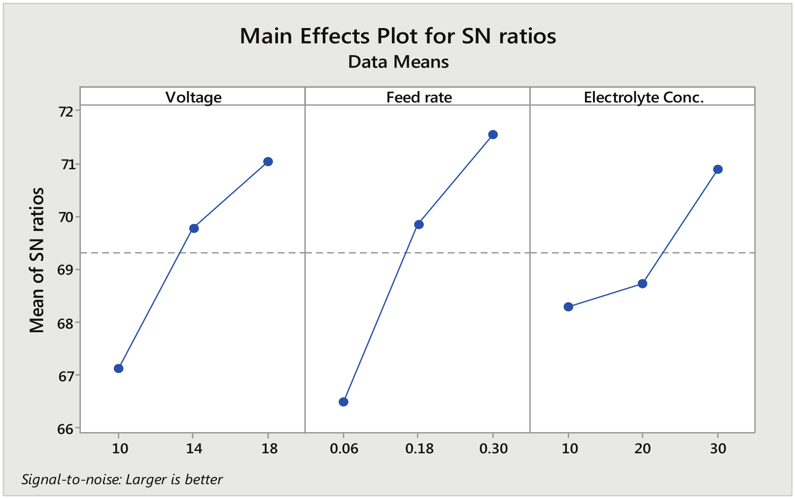
Main effect plot for signal-to-noise ratios (aqueous NaCl as electrolyte).
Regression equation
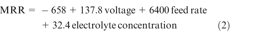
Equation (2) shows that feed rate is the dominant factor affecting the MRR.
The prediction accuracy of the developed models is shown in Figure 6 which shows that the predicted values for MRR are very close with the experimental values and points are scattered very close to the best fit line.
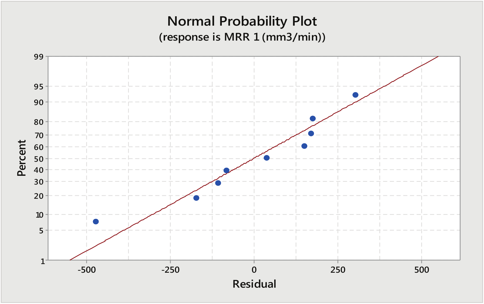
Normal probability plot for MRR (aqueous NaCl as electrolyte).
ANOVA when machining in the presence of CuSO4 mixed aqueous NaCl electrolyte solution
Percentage of contribution of each parameter on MRR during ECM of iron in CuSO4 mixed aqueous NaCl electrolyte solution is shown in Table 5 and represented graphically in Figure 7.
ANOVA for MRR (CuSO4 mixed aqueous NaCl solution as electrolyte).
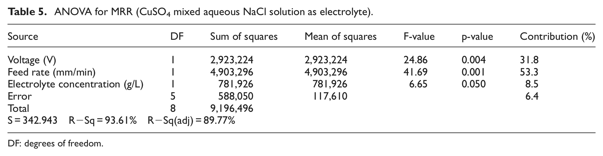
DF: degrees of freedom.
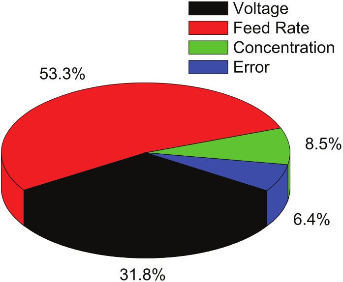
Contribution of parameters (CuSO4 mixed aqueous NaCl as electrolyte).
Figure 8 shows the main effect plot of MRR depicting the effect of machining parameters on MRR while machining in the presence of CuSO4 mixed aqueous NaCl solution. Addition of 0.8 g of CuSO4 per 100 mL of aqueous NaCl proves to be very effective in improving the MRR of the workpiece. As seen from the graph obtained, the MRR improved significantly with increase in both the feed rate and the voltage. Maximum increase in MRR was observed as 18.7 % for the same set of machining conditions.
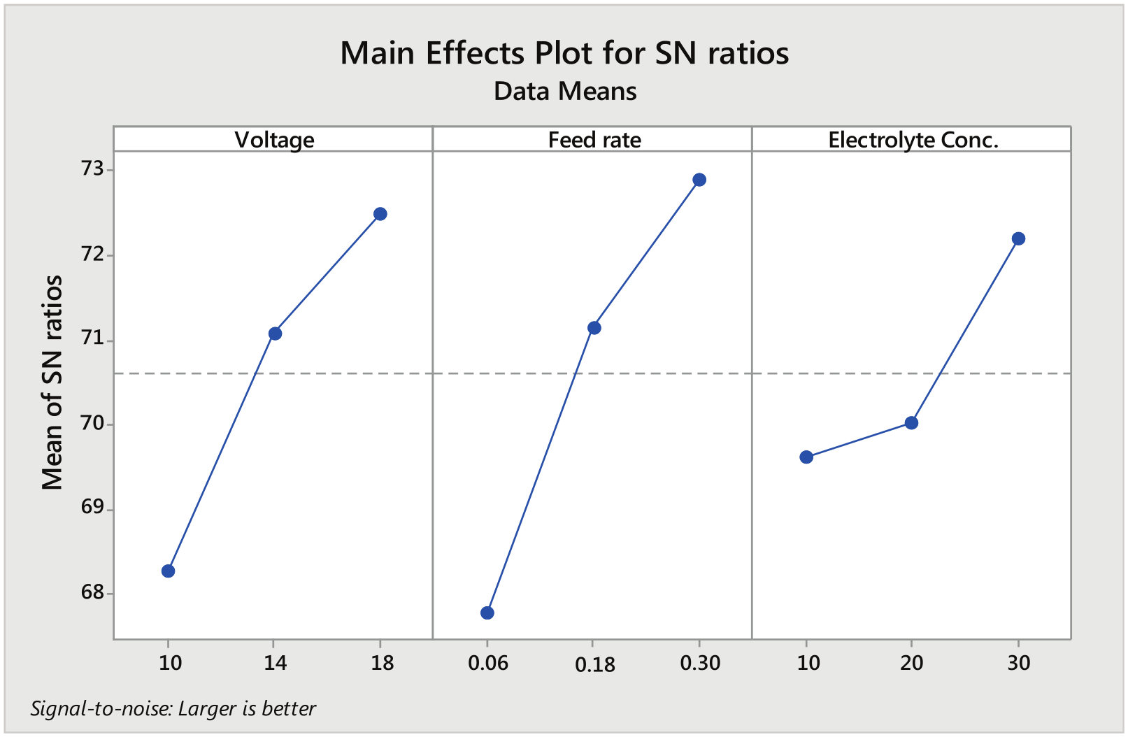
Main effect plot for signal-to-noise ratios (CuSO4 mixed aqueous NaCl as electrolyte).
Regression equation
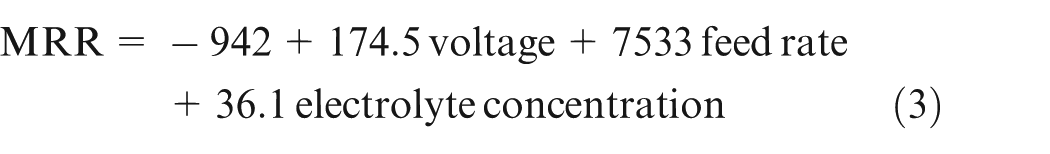
Equation (3) shows that voltage is the dominant factor affecting the MRR.
It can be seen in Figure 9 that all the points on the normal plot lie close to the straight line (mean line). This implies that the data are fairly normal with small deviation from the normality which shows the effectiveness of the developed model.
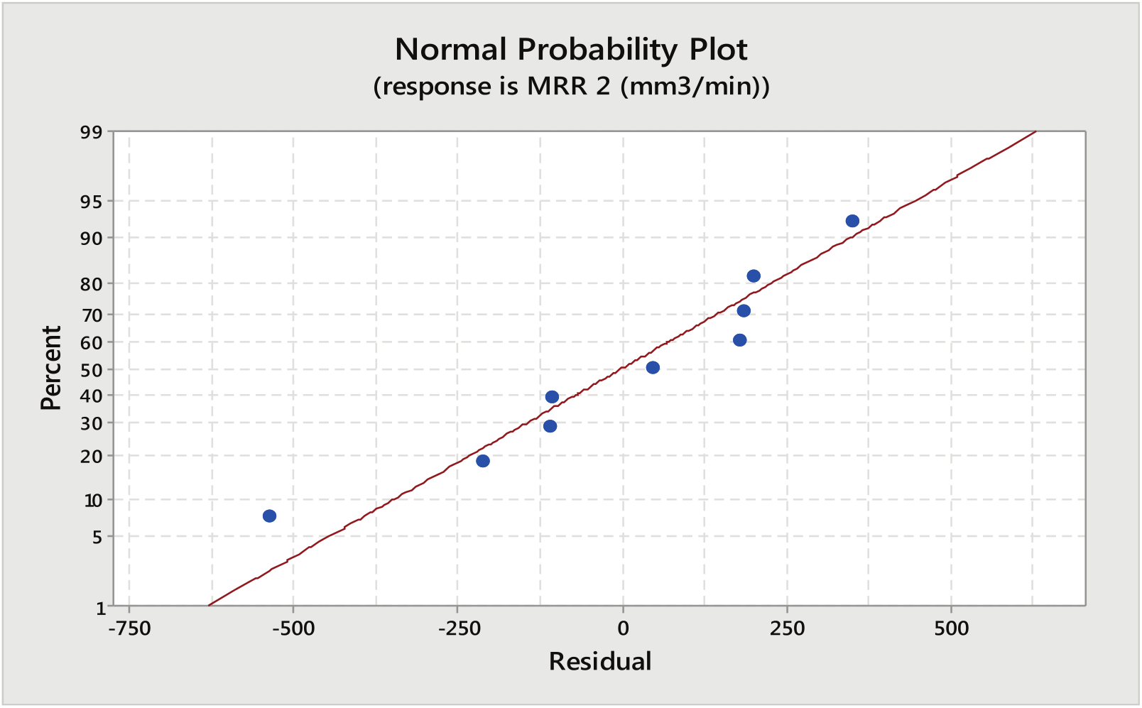
Normal probability plot for MRR (CuSO4 mixed aqueous NaCl as electrolyte).
Conclusion
The electrochemical characteristics of iron in aqueous NaCl solution and CuSO4 mixed aqueous NaCl electrolyte have been analyzed experimentally to investigate the influence of process parameters on MRR. The process parameters, such as voltage, feed rate and electrolyte concentration, were successfully controlled. The different combinations of these parameters were used for the experimentation in order to determine their influence on MRR. The experiment was performed by varying all parameters in combination as per L9 orthogonal array. The experimental observations support the conclusion that the presence of Cu2+ ions in the electrolyte solution prevents the further oxidation of Fe2+ to Fe3+ and enhances the low valence dissolution of iron. Design of experiments and ANOVA helped in identifying the significant parameters affecting MRR. The best combination of the parameters are voltage = 18 V, feed rate = 0.3 mm/min and electrolyte concentration = 20 g/L when using CuSO4 mixed aqueous NaCl solution as electrolyte. The maximum MRR obtained was 18.7 % higher when compared with aqueous NaCl electrolyte for the same set of working conditions.
Footnotes
Acknowledgements
The author(s) express their sincere thanks to the Department of Applied Chemistry BIT Extension Centre Deoghar for their cooperation to conduct the experiments in order to observe the catalytic behavior of Cu2+ ions.
Declaration of conflicting interests
The author(s) declared no potential conflicts of interest with respect to the research, authorship and/or publication of this article.
Funding
The author(s) received no financial support for the research, authorship and/or publication of this article.