
Abstract
With the development of multi-directional forging technology, heavy multi-directional forging press has been widely used in manufacturing industry. However, there is a contradiction between the independence of structure and the independence of mechanics, which becomes a bottleneck and limits the development of heavy multi-directional forging press tonnage. For the contradiction, a novel pre-stressed wire-wound orthogonal preload frame structure is proposed in this article to solve the problem, and the stiffness and deformation characteristic of pre-stressed wire-wound orthogonal preload frame structure under three loading states (vertical–horizontal loading, vertical loading and horizontal loading) are analyzed by finite element analysis and the 1:10 model experiment of 400-MN multi-directional forging press whose loading tonnage in the horizontal direction is the largest tonnage in the world. The results show that pre-stressed wire-wound orthogonal preload frame structure has advantages in large stiffness, high strength and excellent integrity under a reasonable preload coefficient. Furthermore, pre-stressed wire-wound orthogonal preload frame structure can satisfy the design requirement for carrying frame of heavy multi-directional forging press and may promote the development of multi-directional forging technology and related equipment industry.
Introduction
Multi-directional forging (MDF), also called multi-ram forging, uses the vertical and horizontal movements of hydraulic press to make metals produce plastic deformation in the mold cavity.1,2 MDF is an especially attractive technology because it has the potential for scaling up of relatively large samples, which are suitable for industrial applications,3,4 and has been successfully applied to refine the microstructures of bulk billets of titanium alloys, magnesium alloys and high-strength nickel-base alloys.5–8 MDF forges its parts in the process of single heating and single stamping, providing a new way to realize the refinement, less cutting processing, multi-species and low consumption of blank pieces, so MDF is a green manufacturing technology with the characteristics of precision, advanced, energy saving and material saving.9,10
However, the multi-directional forging presses (MDFPs) whose tonnages are more than 10,000 tons are rare in the world as shown in Table 1.11–14
The distribution of heavy MDFPs in the world.
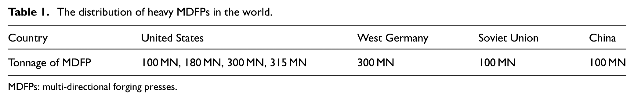
MDFPs: multi-directional forging presses.
Literatures9–12 show that the carrying structures of heavy MDFP are mainly independence frame structure and whole frame structure (Figure 1). The independence frame structure is composed of the vertical frame and horizontal frame that can withstand working load independently and can ensure the independence of mechanics. However, structural interference is easily caused when the vertical frame and horizontal frame withstand working load simultaneously. The whole frame structure uses one carrying frame to withstand the vertical load and horizontal load simultaneously, which can ensure the dependence of structure between the vertical frame and horizontal frame, but stress superposition is easily caused on areas A and B under the working load (Figure 1(b)). Therefore, independence frame structure and whole frame structure cannot meet the independence of mechanics and the dependence of structure simultaneously. 15
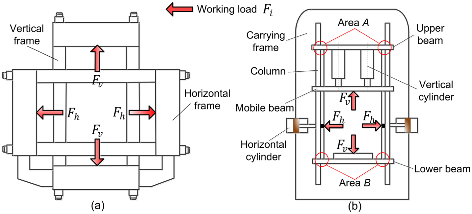
Carrying structures of heavy multi-directional forging press: (a) independence frame structure and (b) whole frame structure.
For the problem, this article proposes a novel pre-stressed wire-wound orthogonal preload frame structure (PWOPFS) as shown in Figure 2. First, the frame of PWOPFS is composed of arc segments and straight line segments. Pre-stressed pressure is only produced on the arc segments of frame contour because the direction of wire layers is changed, and its resultant force is Pi. Likewise, pre-stressed pressure is not produced on the straight line segments of frame contour. Second, in order to balance multi-directional working load Fi, the preload Pi is produced on the arc segments by high-strength pre-stress steel wire layers which are wound on the outside of frame contour, and it can improve the stress state of PWOPFS and eliminate the influence of stress superposition under working load. Finally, PWOPFS uses one frame to withstand the vertical loading and horizontal loading simultaneously, so the structure interference is not caused under working load. Therefore, PWOPFS is able to solve the problems on stress superposition and structure interference simultaneously.
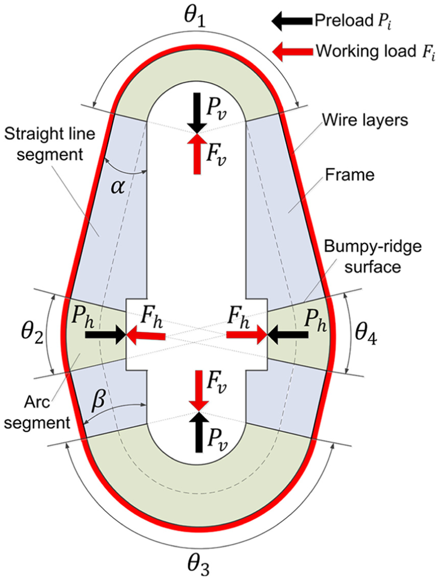
Pre-stressed wire-wound orthogonal preload frame structure.
This article uses finite element analysis (FEA) and 1:10 model experiment of 400-MN MDFP to analyze the feasibility of PWOPFS applied on the carrying structure of heavy MDFP.
Design of PWOPFS
Basic design principles of PWOPFS
Applying the design ideas to the carrying frame of 400-MN MDFP, basic design principles of PWOPFS are described in this article. For 400-MN MDFP (Figure 3), the total carrying tonnages of the vertical direction and horizontal direction are 400 and 100 MN, respectively. In order to place the vertical cylinder and horizontal cylinder comfortably, the double arch structure is applied to the 400-MN MDFP. In addition, the carrying tonnages of the vertical direction and horizontal direction are, respectively, 200 and 50 MN for the single PWOPFS of 400-MN MDFP. The appearance size of the PWOPFS is 23.818 m × 13.181 m × 1.100 m, the weight is 835,000 kg and it is very difficult to manufacture the PWOPFS as a whole structure because it has touched the limit capacity of casting, forging, welding and transportation. For this problem, PWOPFS of 400-MN MDFP can be divided into some special positions, and the method of bumpy-ridge structure16,17 can be used to realize the integrity of PWOPFS. Bumpy-ridge structure means that the division surfaces, processed into a multi-peak structure, are combined by pre-stressed wire-wound technology and form the embedded structure that has a capacity of resisting shear stress. In order to make each bumpy-ridge surface with minimum shear force, ensure straight line segments and arc segments are been easily processed and avoid stress concentration at the root of the column, PWOPFS is divided at the intersection of straight line segments and arc segments along the outer contour and its integrity is realized by micro bumpy-ridge structure and wire-wound preload force on each bumpy-ridge surface (Figure 2).
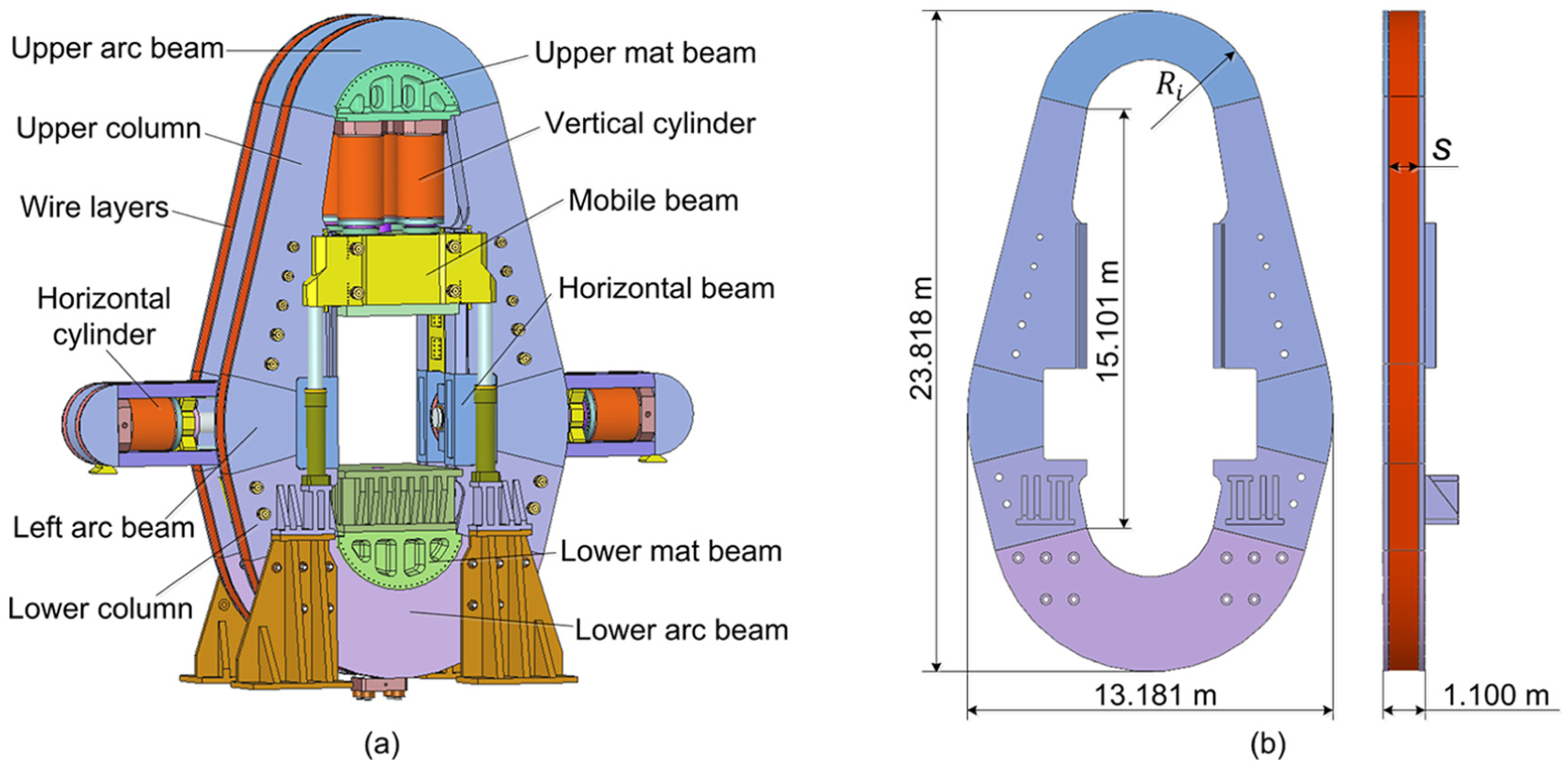
400-MN multi-directional forging press: (a) main structure and (b) pre-stressed wire-wound orthogonal preload frame structure.
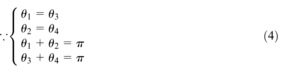
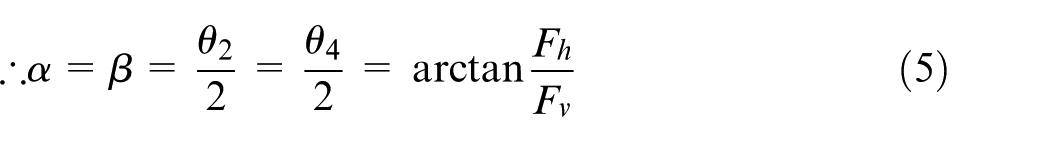
The column of PWOPFS is composed of two straight line segments and one arc segment, and the angles between the upper or lower straight line segment of the column and the vertical direction are α and β, respectively (Figure 2). α and β are directly related to the overall layout, internal structure and the carrying tonnage of PWOPFS. When the angles α and β are reasonable, the carrying tonnage of PWOPFS in the horizontal will be enhanced and there has been a large space for the internal structure of the layout within PWOPFS. Following the design principles of PWOPFS, in order to have the same preload force in the upper straight line segment and the lower straight line segment, α = β as follows
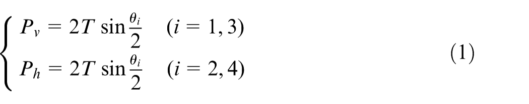

Because the tension of wire layers is equal on the outer contour of PWOPFS, equation (3) can be obtained by equations (1) and (2) as follows
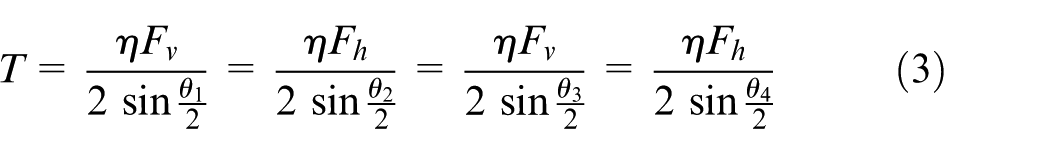
where η is the preload coefficient of PWOPFS, T is the tension of wire layers, θi is the central angle of arc segments, Ph, v is the preload and Fh, v is the working load.
Therefore, the tension of wire layers and the central angel of arc segments can be calculated when the vertical working load, horizontal working load and preload coefficient of MDFP are known, and the overall design and layout for PWOPFS can be done.
Finite element method of stiffness ratio
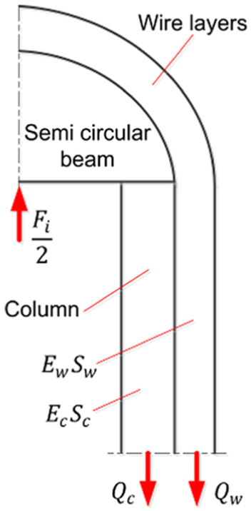
Stiffness ratio is the ratio of load distribution between wire layers and frame under load, which is an important parameter to analyze the mechanical properties of PWOPFS in the working state. The tension of wire layers of pre-stressed wire-wound frame consists of two parts: preload tension produced by pre-stressed wire-wound technology and carrying tension produced by working load Fi. The force diagram of pre-stressed wire-wound frame in the working state is shown in Figure 4, and equation (6) can be obtained as follows18–20
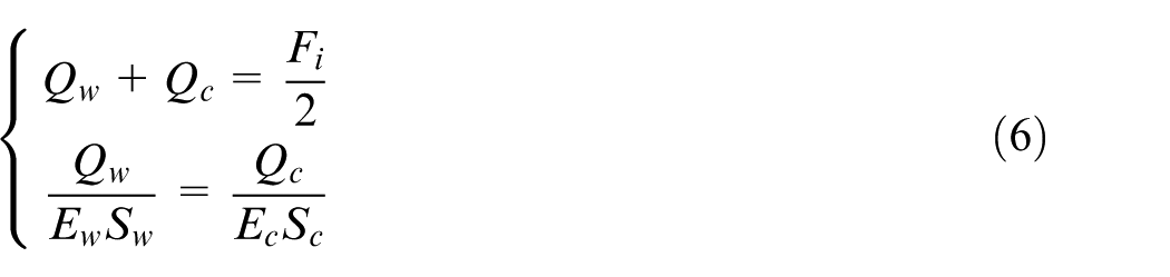
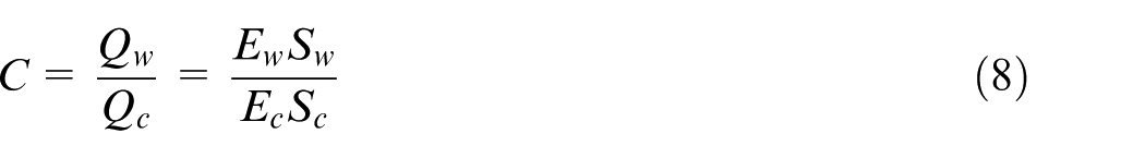
where Qw and Qc are the carrying load of wire layers and column under working load Fi, respectively, Sw and Sc are the cross-sectional area of wire layers and column, respectively, Ew and Ec are the elastic modulus of wire layers and column, respectively, and C is the stiffness ratio of pre-stressed frame.
Force diagram of pre-stressed wire-wound frame in the working state.
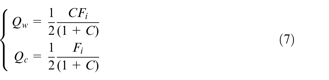
According to equations (3) and (7), surface pressure qi of arc segments of PWOPFS caused by wire layers can be obtained by equation (9), as follows
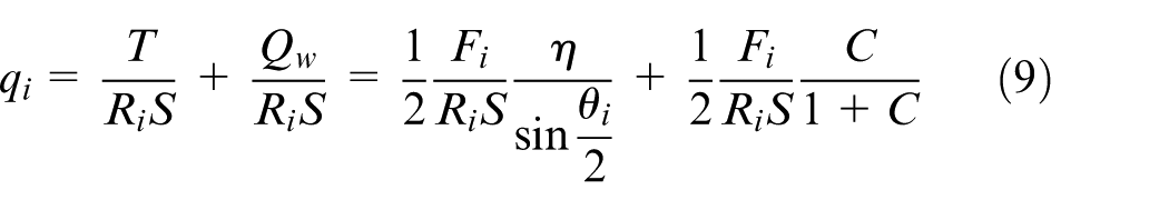
where Ri is the radius of arc segments, and S is the width of wire layers (Figure 3(b)). The first part of equation (9) is the surface pressure produced by preload, and the second part of the equation (9) is the surface pressure produced by working load.
As shown in equation (9) and Figure 6, C is an important parameter for PWOPFS to do FEA and structural design. However, equation (8) cannot be used directly to calculate the stiffness ration C of PWOPFS because the column of PWOPFS is composed of two tapered straight line segments and one arc segment. It is difficult to find an equivalent cross section to apply equation (6). Therefore, a finite element method is used to calculate stiffness ratio of PWOPFS as follows.
where the diagram of wire layers’ meshing on the finite element method of stiffness ration is shown in Figure 5. In the circumference direction of wire layers, select the nodes a, b, c, d, e and so on. The length of wire layers between the two nodes before loading (lab, lbc, lcd, lde, …), the length of wire layers between the two nodes in loading (l′ ab , l′ bc , l′ cd , l′ de , …), the length variation in wire layers between the two nodes before and after loading (Δlab, Δlbc, Δlcd, Δlde, …) and the average stress of wire layers σave can be, respectively, obtained by equations (10)–(13) as follows
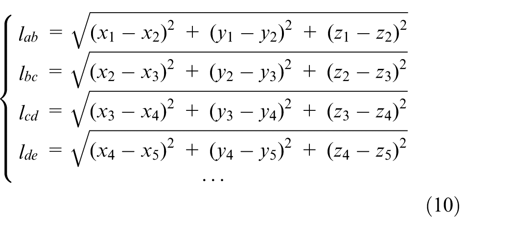
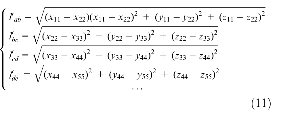
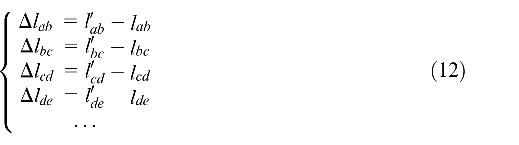
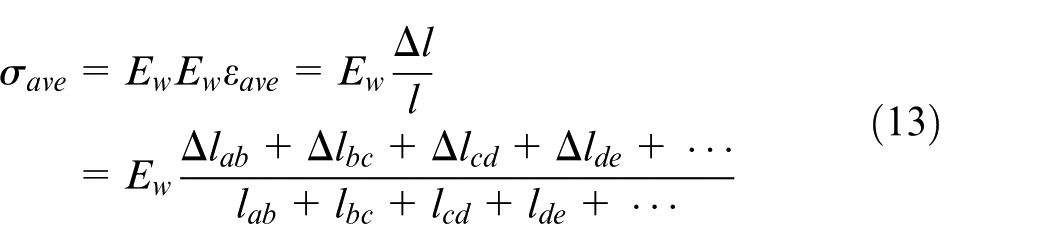
where εave is the average strain of wire layers, l is the total length of wire layers and Δl is the variation in total length of wire layers.
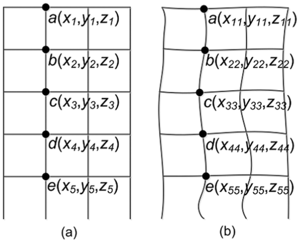
Diagram of wire layers’ meshing: (a) before loading and (b) loading.
According to the definition of stiffness ratio, stiffness ratio C can be obtained by equation (14) as follows
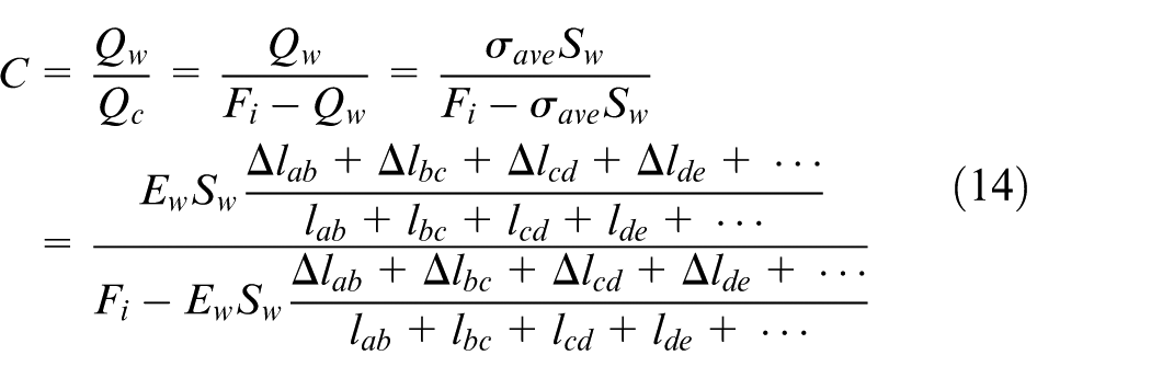
Therefore, stiffness ratio C of PWOPFS can be obtained by equation (14) when working load Fi, the elastic modulus of wire layers Ew and the cross-sectional area of wire layers Sw are known.
Analysis of mechanical properties for PWOPFS
According to the forming characteristics of MDF technology, analysis of mechanical properties for PWOPFS can be attributed to elastic statics. Solving the problems of elastic statics with model experiment and finite element method is an effective and economical way in the engineering field. 21 Therefore, using FEA and 1:10 model experiment for 400-MN MDFP to demonstrate the feasibility of PWOPFS is applied to the carrying frame of MDFP.
FEA for PWOPFS
In the working time, MDFP has three loading states: vertical–horizontal loading state, vertical loading state and horizontal loading state, so the FEA of the stiffness and integrity of PWOPFS should be, respectively, analyzed under three loading states.
In the vertical direction, a 400-MN force which is produced by the vertical cylinder is directly loaded on the horizontal parting surface of mold, which can provide enough clamping force to make 400-MN MDFP be in the state of center loading while the horizontal load is loaded on the frame. Therefore, this article only takes the state of center loading into account while analyzing the mechanical properties for 400-MN MDFP.
According to the structure symmetry and load symmetry of 400-MN MDFP, 1/4 geometric model of 400-MN MDFP is used to analyze the stiffness and integrity of PWOPFS by commercial soft ABAQUS. The 1/4 geometric model is dispersed by tetrahedron element C3D10 and hexahedron element C3D20R, and its local area is refined by tetrahedron element C3D10. Elastic modulus and Poisson’s ratio are E = 2.09 × 10⁵ MPa and υ = 0.3, respectively.
FEA for the integrity of PWOPFS
Friction coefficient on each bumpy-ridge surface is 0.3, and the others are 0.2. q1, q2 and q3 are loaded on the arc segments of PWOPFS by the form of surface pressure in order to replace the preload force of wire layers in the vertical and horizontal directions. q4, q5 and q6 are, respectively, loaded on the upper mat beam, lower mat beam and horizontal beam by the form of surface pressure in order to replace working load in the vertical and horizontal directions (Figure 6(a)).
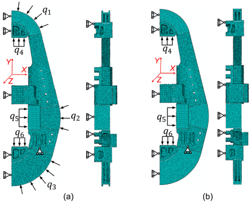
The model of finite element analysis: (a) analysis of the integrity and (b) analysis of the stiffness.
FEA for the stiffness of PWOPFS
Tie constraint is applied to each bumpy-ridge surface, and friction coefficient of the other contact surfaces is 0.2. q4, q5 and q6 are, respectively, loaded on the upper mat beam, lower mat beam and horizontal beam by the form of surface pressure in order to replace working load in the vertical and horizontal directions (Figure 6(b)).
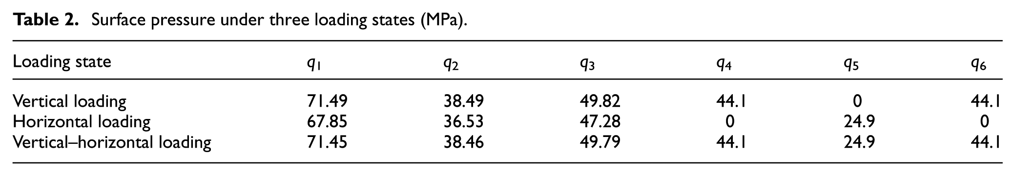
According to equation (14), the stiffness ration C of vertical loading, horizontal and vertical–horizontal loading can be obtained, which is 0.156, 0.0482 and 0.154, respectively. The surface pressure of each part of PWOPFS can be obtained by equation (9) under three load states, which is shown in Table 2. The calculation conditions are Fv = 200 MN, Fh = 50 MN, S = 0.8 m, η = 2.0, θ1 = θ3 = 152°, θ2 = θ4 = 28°, R1 = 3.84 m, R2 = R4 = 7.15 m and R3 = 5.51 m.
Surface pressure under three loading states (MPa).
FEA of the integrity
The integrity of PWOPFS directly relates to the service life and safety of MDFP for that the pre-stressed wire-wound bumpy-ridge technology is applied to PWOPFS. When the working load of forging press exceeds the preload that is produced by the pre-stressed wire-wound technology on the bumpy-ridge surface in the working time, a gap and slid appear and this phenomena is called slippage and dislocation. If there is a slippage and dislocation on the surface of the bumpy-ridge, the preload of PWOPFS will decrease rapidly after bearing the working load repeatedly. In the working time, slippage and dislocation are easily produced on the bumpy-ridge surface of PWOPFS because of the effect of bending moment which is caused by working load and will directly affect the integrity of PWOPFS. Residual pre-stress on each bumpy-ridge surface, especially on the inside and outside (Figure 7), is an important criterion to judge whether there is a phenomenon of slotting and offsetting or not. Therefore, residual pre-stress on each bumpy-ridge surface must be analyzed as an important problem.
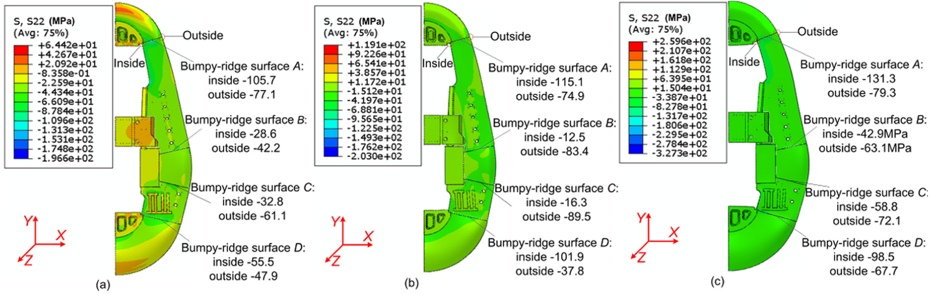
Stress distribution in the Y-direction (the figure magnified 100 times): (a) vertical–horizontal loading, (b) vertical loading and (c) horizontal loading.
For PWOPFS of 400-MN MDFP, the stress distribution in the Y-direction under three loading states is shown in Figure 7.
From inside to outside of each bumpy-ridge surface, Figure 7 shows that the minimum stress values under three loading states are all produced on the bumpy-ridge surface B. The minimum values under vertical–horizontal loading state, vertical loading state and horizontal loading states are, respectively, −28.6, −12.5 and −42.9 MPa, demonstrating that the phenomena of slippage and dislocation are not produced on each bumpy-ridge surface of PWOPFS of 400-MN MDFP.
FEA of the stiffness
For MDFP, the deformation of PWOPFS reflects the stiffness in the working time and affects the dimensional accuracy of forgings and the service life of hydraulic system directly.
From the perspective of global deformation, the stiffness of PWOPFS under three load states will be directly reflected by the following aspects: the deformation of PWOPFS in the horizontal direction, equal to two times the displacement of point c in the X-direction because of structural symmetry, will affect the dimensional accuracy of forgings in the horizontal direction; the deformation of PWOPFS in the vertical direction, equal to the difference between the displacement of point a and the displacement of point b in the Y-direction, will affect the dimensional accuracy of forgings in the vertical direction; the swing of PWOPFS in the Z-direction, equal to the displacement of point a or point b in the Z-direction, will affect the service life of the hydraulic system.
The displacement of PWOPFS in the X-, Y- and Z-directions under three loading states is shown in Figure 8.
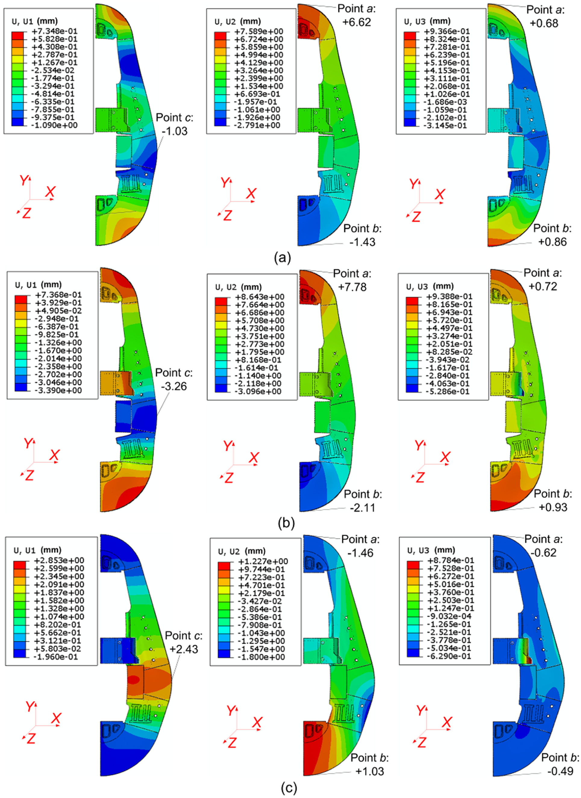
The displacement of PWOPFS under three loading states (the figure magnified 200 times): (a) vertical–horizontal loading, (b) vertical loading and (c) horizontal loading.
The angle (α or β which is showed in Figure 2) between straight line segments of column and vertical direction maybe cause insufficient stiffness of column and influent the stiffness of MDFP under three loading states. The deformation of the column of PWOPFS can be seen as the deformation of beam under working load, so the deflection can be used to assess the stiffness of the column in the X-direction. The total length of the column of 400-MN MDFP is 15.101 m (Figure 3(b)). Figure 8 shows that the maximum deflections of the column in the X-direction under vertical–horizontal loading, vertical loading and horizontal loading are, respectively, −1.03, −3.26 and +2.43 mm, so the maximum variations in the deflection of the column in the X-direction under three loading states are, respectively, −0.07, −0.22 and +0.16 mm/m which are smaller than the width (that is, 13.181 m) of PWOPFS. Therefore, the stiffness of the column of PWOPFS is very good under three loading states.
The similarity of 1:10 model
The mechanical structure of heavy MDFP is complex and high stress in the working time. To ensure the safety, the experiment and numerical analysis of 400-MN MDFP should be done. However, the process of the experiment is difficult and the cost of the experiment is expensive because of the size and weight of 400-MN MDFP, so the stiffness and integrity of PWOPFS are analyzed with 1:10 model which is strictly similar to 400-MN MDFP.
The PWOPFS of 1:10 model is a welding structure, on which the material Q345 is applied. The carrying loads of the vertical and the horizontal directions are 4 and 1 MN, respectively. 1:10 model and 400 MN MDFP have the same Poisson’s ration and elastic modulus, and their size ratio is 1:10. According to the principles of elastic static similarity for pre-stressed structure, 22 equations (15) and (16) can be obtained as follows
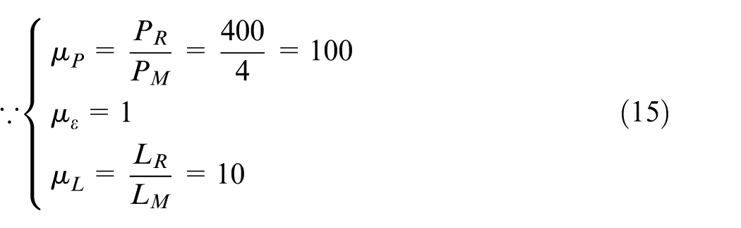

where µP is the similarity ratio of load, PR and PM are the carrying capacity of 400-MN MDFP and 1:10 model, respectively, µL is the similarity ratio of geometry, LR and LM are the size of 400-MN MDFP and 1:10 model, respectively, µσ is the similarity ratio of stress, µε is the similarity ratio of strain, Δ R and Δ M are the displacement of 400-MN and 1:10 model, respectively, and µΔ is the similarity ratio of the displacement.
The experiment of 1:10 model
1:10 model of 400-MN MDFP is composed of PWOPFS, mobile beam, workbench, hydraulic cylinder, oil pump, supporting foot and so on, which can completely meet the conditions of the experiment (Figure 11(b)).
Analysis of the integrity
As is shown in Figure 7, the stress values on the inside and outside of bumpy-ridge surface B are smaller than those of bumpy-ridge surfaces, which indicate that the residual pre-stress of bumpy-ridge surface B is the smallest, so the phenomena of slippage and dislocation are easily produced inside and outside of the bumpy-ridge surface B.
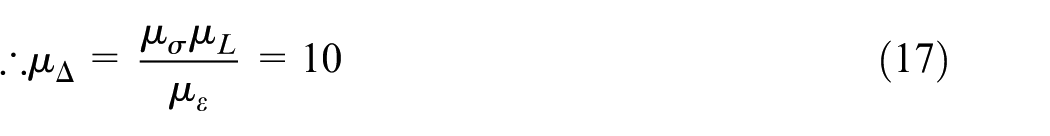
Electronic microscope KEYENCE is used to observe the inside and outside of bumpy-ridge surface B before and after loading during the experiment as shown in Figure 9. The experimental results are shown in Figure 10.
Analysis of the integrity: (a) location of experiment point and (b) experiment site.
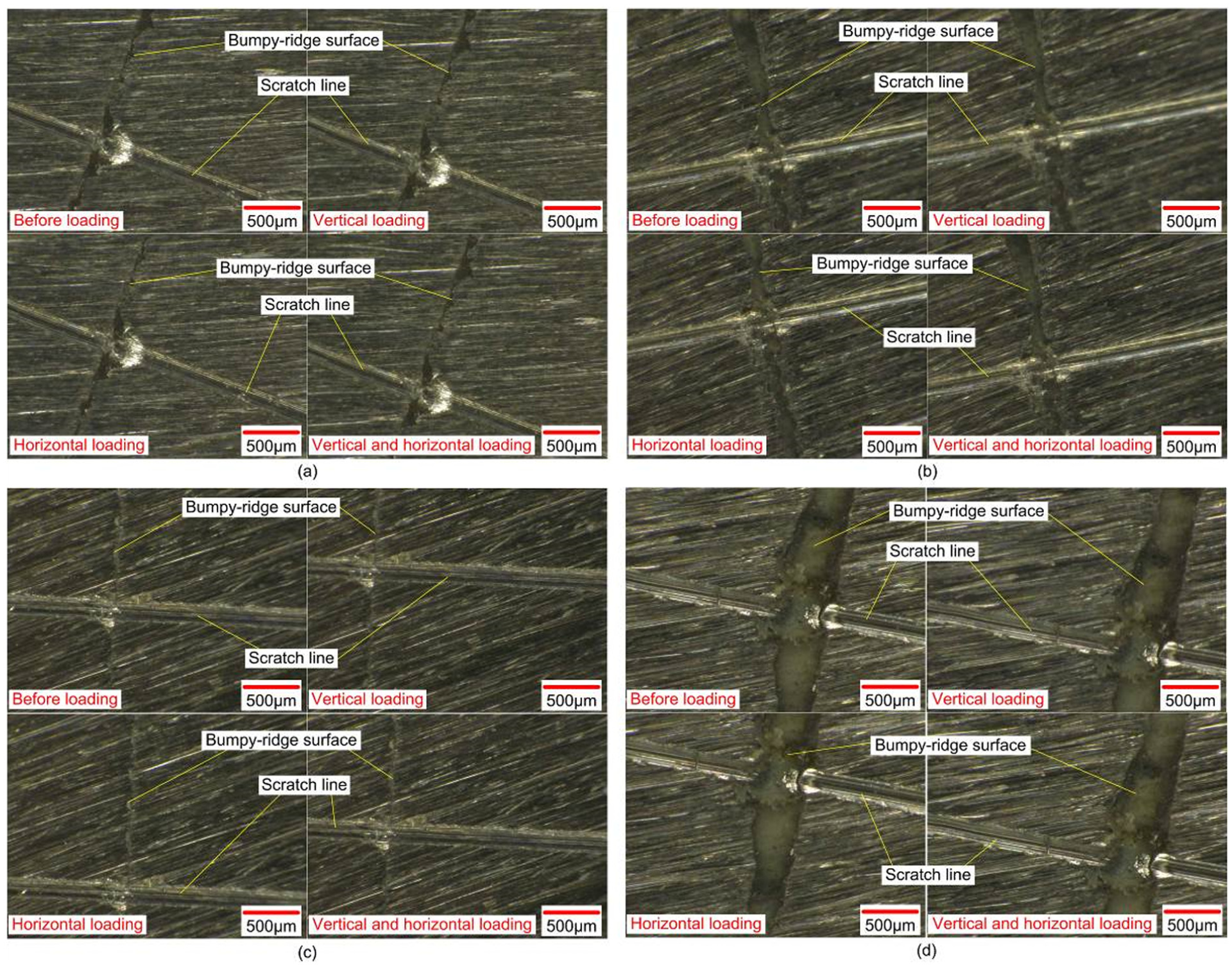
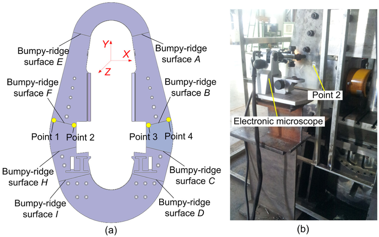
Experimental results of each test point under three loading states: (a) experimental results of test point 1 before and after loading, (b) experimental results of test point 2 before and after loading, (c) experimental results of test point 3 before and after loading and (d) experimental results of test point 4 before and after loading.
As shown in Figure 10, the scratch line is used to observe the phenomenon of slippage, and the bumpy-ridge surface is used to observe the phenomenon of dislocation. Figure 10(a)–(d) shows that the phenomenon of slippage is not produced on each bumpy-ridge surface, and the scratch lines do not produce obviously dislocation at points 1, 2, 3 and 4 during the experiment of 1:10 model. Therefore, the experiment of 1:10 model of 400-MN MDFP can demonstrate that the integrity of PWOPFS is better under the three loading states.
Analysis of the stiffness
The measurement frame is the datum of dial indicator (Figure 11(b)). The value of dial indicator directly demonstrates the deformation of PWOPFS before and after loading. Referring to Figures 8 and 11, points 1 and 2 are used to measure the deformation of PWOPFS in the Y-direction, points 3 and 4 are used to measure the deformation of PWOPFS in the X-direction and points 5 and 6 are used to measure the deformation of PWOPFS in the Z-direction. Three tests are done at each experiment point. The location of the experiment point and the experiment site are shown in Figure 11.
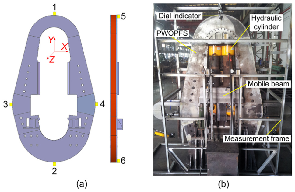
Analysis of the stiffness: (a) location of experiment point and (b) experiment site.
In the design process of 1:10 model, the similarity ration of displacement is µΔ = 10 (Δ R = 10Δ M ), so the actual deformation value of 400-MN MDFP is 10 times of 1:10 model before and after loading. The actual deformation values of 1:10 model in the X-, Y-, and Z-directions are shown in Tables 3–5, respectively.
The deformation of X-direction (mm).
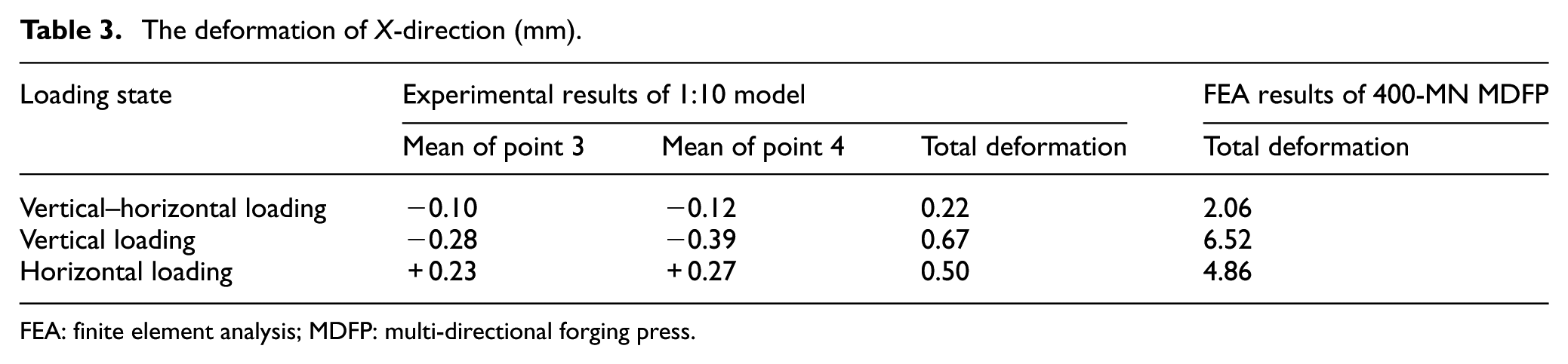
FEA: finite element analysis; MDFP: multi-directional forging press.
The deformation of Y-direction (mm).
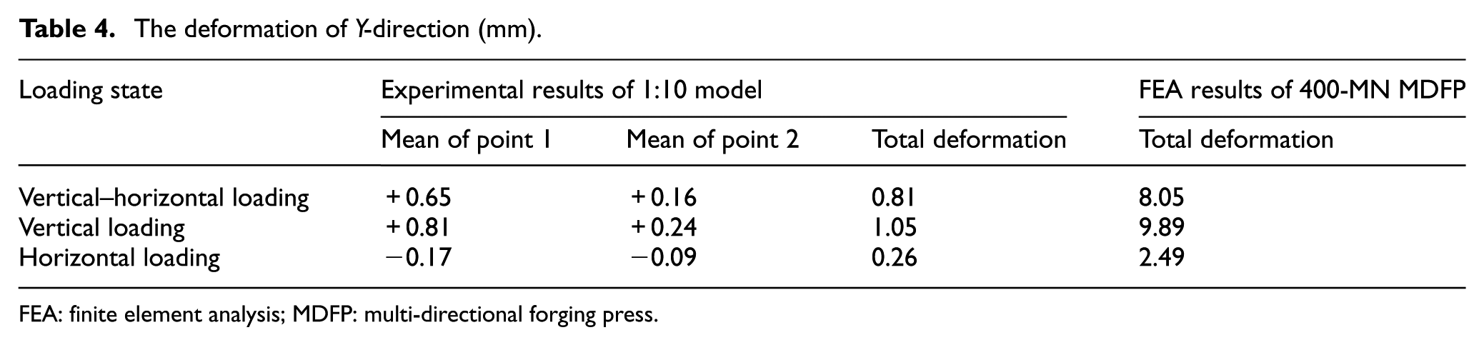
FEA: finite element analysis; MDFP: multi-directional forging press.
The deformation of Z-direction (mm).
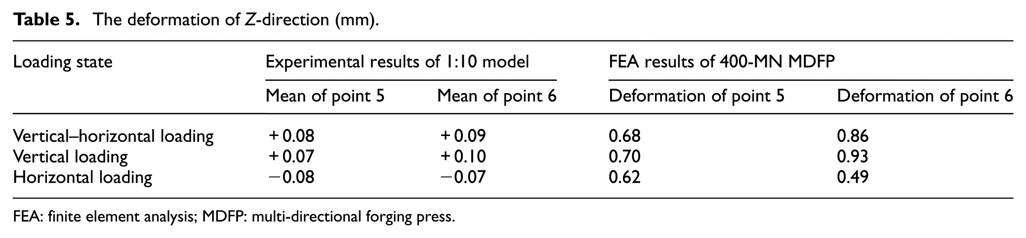
FEA: finite element analysis; MDFP: multi-directional forging press.
Tables 3–5 show that the maximum deformations of 1:10 model in the X-, Y-, and Z-directions are, respectively, 0.22, 0.81 and 0.09 mm under vertical–horizontal loading state. According to equation (18), the actual deformations of PWOPFS of 400-MN MDFP in the X-, Y- and Z-directions are, respectively, 2.2, 8.1 and 0.9 mm under vertical–horizontal loading state. Likewise, the actual deformations are, respectively, 6.7, 10.5 and 1.0 mm under vertical loading state, and the actual deformations are, respectively, 5.0, 2.6 and 0.8 mm under horizontal loading state. Compared with the whole size (that is 23.818 m × 13.181 m × 1.100 m) of PWOPFS of 400-MN MDFP, the maximum deformation rate of PWOPFS does not exceed 1‰, which is completely within the reasonable range. Besides, Figure 8 shows that the maximum deformations of PWOPFS of 400-MN MDFP in the X-, Y- and Z-directions are, respectively, 6.52, 9.89 and 0.93 mm, which are smaller than the whole size of PWOPFS under three loading states, demonstrating that the stiffness of PWOPFS is very good. Therefore, the results of FEA and experiment of 1:10 model for 400-MN MDFP show that the stiffness of PWOPFS is better under three loading states.
Tables 3–5 show that the actual deformations of PWOPFS of 400-MN MDFP obtained with the 1:10 model experiment in the X-direction under vertical–horizontal, vertical and horizontal loading are 2.2, 6.7 and 5.0 mm, respectively, and the deformations of FEA results of 400-MN MDFP are 2.06, 6.52 and 4.86 mm, respectively. The actual deformations of PWOPFS in the Y-direction under vertical–horizontal, vertical and horizontal loading are 8.1, 10.5 and 2.6 mm, respectively, and the deformations of FEA results are 8.05, 9.89 and 2.49 mm, respectively. In a word, the total deformations of PWOPFS of 400-MN MDFP calculated by FEA are very similar to the actual experiment results obtained with the 1:10 model experiment, which demonstrates the feasibility and reference value of using FEA to analyze the mechanical properties of PWOPFS. Besides, the total deformations of PWOPFS of 400-MN MDFP obtained by the actual experiment are greater than that obtained by FEA because of the gap between the mobile beam and its guiding surface, and the gap may reduce the limiting role of the mobile beam for PWOPFS during the 1:10 model experiment.
Conclusion
For the contradiction between the independence of structure and the independence of mechanics in the mechanism design of heavy MDFP, this article proposes a novel PWOPFS, and the basic design principles of PWOPFS are described by 400-MN MDFP. The overall design and layout of PWOPFS can be done when the vertical working load, horizontal working load and preload coefficient of PWOPFS are known.
It is important for the heavy MDFP that uses PWOPFS as the carrying frame to ensure the safety because of its massive quality, complex structure and high stress in working time. However, the cost of the experiment is large and the process of the experiment is difficult for heavy MDFP, so the methods of FEA, similarity theory and model experiment which are proposed in this article may provide an important reference for the design of heavy MDFP.
The results of FEA and 1:10 model experiment for 400-MN MDFP show that the stiffness and integrity of PWOPFS are very good, which can completely demonstrate the feasibility of PWOPFS as a carrying frame of MDFP. Therefore, PWOPFS is a new technology breakthrough for carrying frame of heavy MDFP and can provide many technical supports and important opportunities for MDF manufacturing technology.
Footnotes
Declaration of conflicting interests
The author(s) declared no potential conflicts of interest with respect to the research, authorship and/or publication of this article.
Funding
The author(s) disclosed receipt of the following financial support for the research, authorship, and/or publication of this article: The authors would like to acknowledge the funding of National Science and Technology Major Project of China, No. 2012Z X04010082.