
Abstract
A new approach is presented in this article for modeling and analysis of precise end-face grinding burr formation. The aim of this approach is to develop an automatic online deburring method that utilizes a precision motion control mechanism and effective deburring tools. Servo valve cores widely used in aerospace industry were employed as the workpiece in this study. After precision external grinding process, as a rule, the way of end-face grinding is adopted to get qualified working edges; the precision of these edges are generally required to be micron level or higher. However, after end-face grinding, the outside circle of the working edges will have burrs whose heights range from a few to dozens of microns, and the manual offline burr removal method currently adopted is not only uneasy to control accuracy but also easy for the working edges of the workpiece to lose its integrity and lead to a high rejection rate. In this article, the burr modeling and analysis procedure were used to get the corresponding formation mechanism of burr, and the online precision burr removal equipment was designed reasonably. Therefore, the effective removal of arising micro-burr from end-face grinding and the accuracy of the working edges were very well guaranteed, so as to improve the production efficiency.
Keywords
Introduction
Burr formation is one of the most common phenomena in the metal cutting process, and it has an adverse influence on processing quality, assembly and application in subsequent processes. Deburring operations are time- and money-consuming processes, which badly affect the automatic pipeline manufacture and metal cutting processes. Burr is a special kind of chips. And in grinding process, due to the influence of burr size, deburring is different from other processes. In order to improve the processing quality of grinding parts, it is particularly important to understand burr formation mechanism and influence factors in grinding process. In early 1976, the first quantitative analysis of burr was conducted by Gillespie and Blotter, 1 and he proposed that burr is the material deformation at the end of the workpiece. David A. Dornfeld and his research team (Consortium on Deburring and Edge Finishing (CODEF) in Laboratory for Manufacturing and Sustainability (LMAS) of UC-Berkeley) made many contributions on the fields of burr formation mechanism and its suppression methods, which consisted of some finite element modeling (FEM) work. For example, Ko and Dornfeld 2 proposed a quantitative ductile material model on the burr size of milling process.
Deburring is a finishing process which utilized bound abrasives or deburring tools to remove the sharp edges and burrs on a workpiece. According to burr size, workpiece dimensions, location and series of parts to be manufactured, various approaches are proposed to carry out the deburring operation—for instance, manual processes by sand papering, hand scratching and hand filing or automatically by countersinking, thermal energy, high pressure water jet and electrochemical machining. In the past, limited researches have been carried out to investigate various methods for automatic online deburring system, especially in the field of precise end-face grinding process.3–10
Spool valve is composed of valve spool and valve sleeve, and as the power stage of servo valve, it has a high degree of accuracy and is difficult for machining. Servo valve core is an axial part and a core power amplifier stage component of the servo valve spool. Fitting accuracy between the working edges and throttling window of valve sleeve determines the performance of the valve. In the machining process, face grinding is the final step during which micro burrs emerge. These burrs have a great influence on the accuracy and stability of servo valve core. At present, after the grinding, an offline method was chosen to remove the burrs. In a manual deburring process, with the workpiece fitted on an offline deburring device, the surface of the workpiece edges is repeatedly squeezed with polished carbide bar and razor blades wrapped in metallographic sandpaper, respectively. This method is inefficient and easy to damage the integrity of working edges. The manual deburring method is shown in Figure 1. Automation is a potential solution to overcome this problem. However, the successful implementation of an automatic deburring method requires creative breakthroughs.
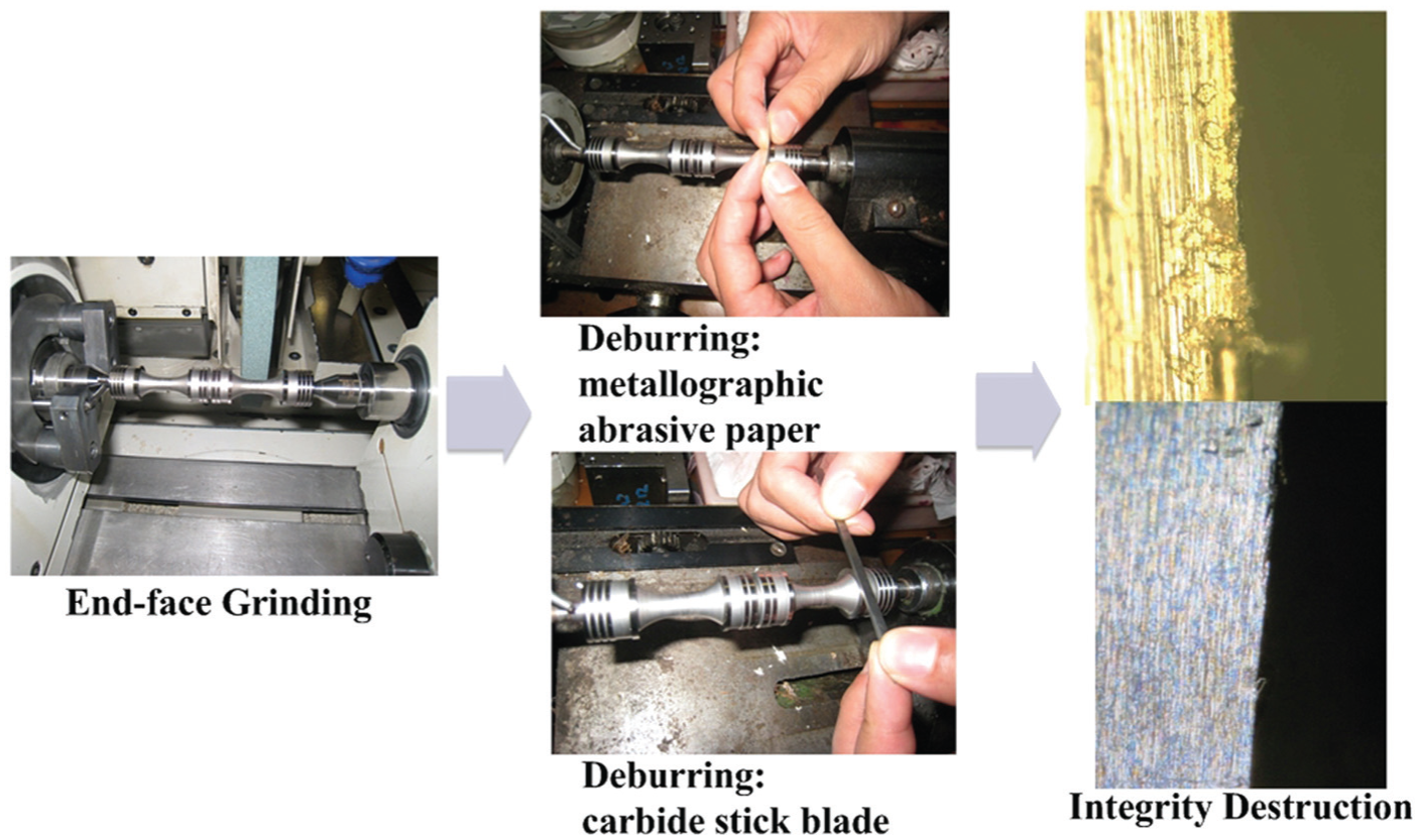
Manual deburring method and the defect.
One of the most significant problems encountered in servo valve machining is burr formation. All edges must be completely defect-free with strict radii, for the following operation, safety and precision. On one hand, the micron burrs of the servo valve core edge are extremely small which has made deburring process more difficult. On the other hand, the final machining dimensional accuracy is also at micron level, namely, the sizes of micro defects and the function sizes of precision parts are very close. Therefore, the difficulty of deburring is extremely great. Figure 2 shows the structure diagram of the servo valve, and the technical requirements are as follows:
Fit clearance (cylindrical diameter of valve core and pore diameter of valve sleeve): 2–4 µm;
Axial coordination (working edges and throttle window on the valve sleeve): Overlap: 2–4 µm; Perpendicularity: 1 µm;
No burr on working edge and fillet radius is less than 2 µm.
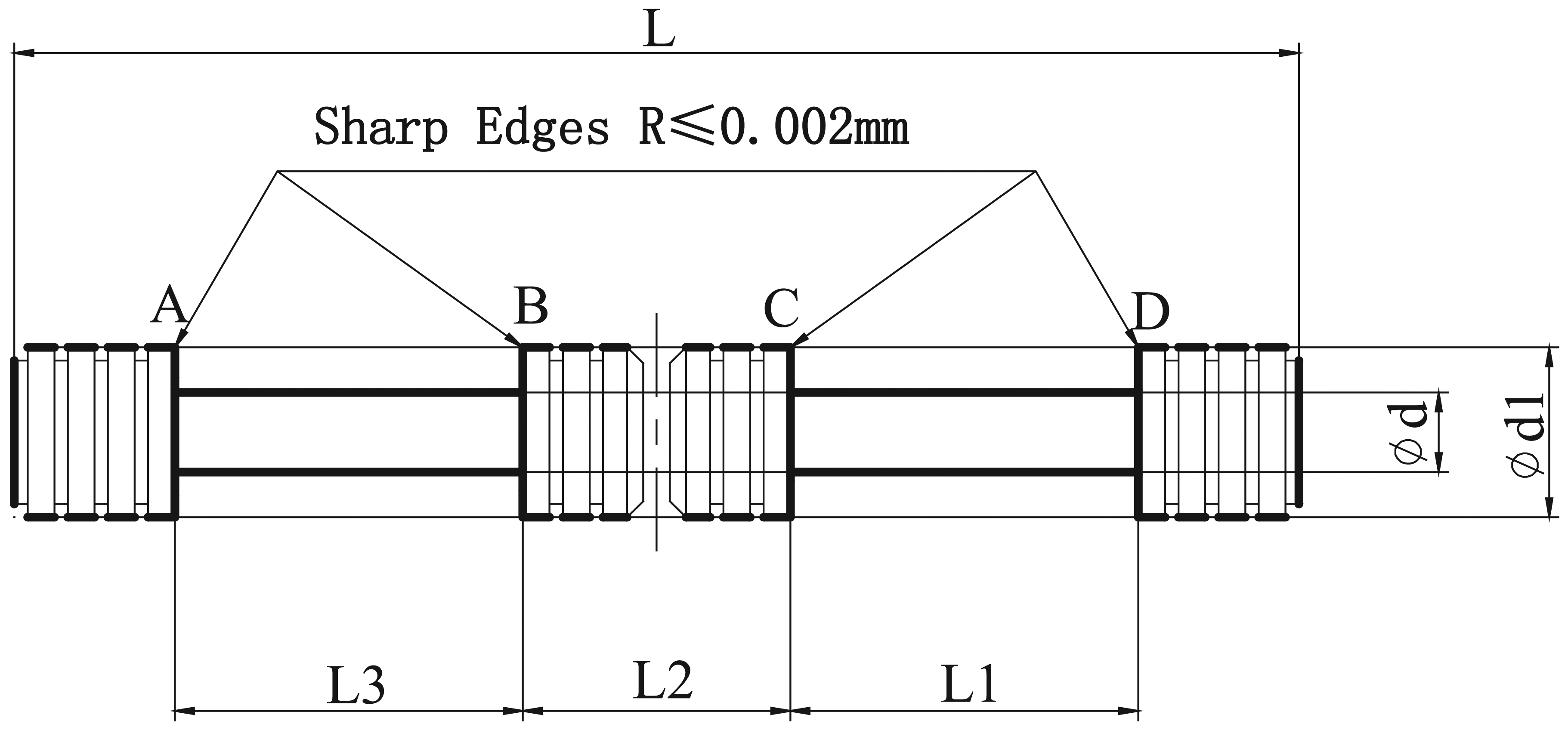
Structure diagram of the servo valve.
Manual operation for deburring is featured as labor intensive, highly skill dependent, high cost and prone to error. Previous studies of automatic deburring methods are either not suitable for online deburring in micron scale or easy to damage the workpiece surfaces adjacent to the burr region.11–13 This article presents a new approach to develop an automatic online micro-deburring method that utilizes a precision motion control mechanism and effective deburring tools. Burr modeling and analysis procedure were used in this article to get the corresponding formation mechanism of burrs, and a reasonable design of online precision burr removal equipment was adopted. With the combination of simulations and experiments, the quantitative analysis of the burr carries out to achieve precision removal of micron burrs.
Burrs in end-face grinding
Micro-burrs formation
With regard to FEM of the cutting process, this article uses the material constitutive model proposed by Johnson and Cook (JC), 14 that is, JC model, which is the most commonly used constitutive model for simulating the cutting process. The expression is
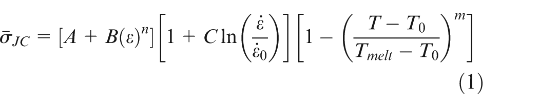
JC model expresses material flow stress as the product of three terms, respectively, material strain hardening, strain rate hardening and temperature hardening, and A, B, C, m and n are the unknown parameters which can be obtained by experiments.
For modeling of the tool–workpiece contact, Coulomb friction is applied. Meanwhile, this article uses Arbitrary Lagrange–Euler (ALE) technique since large deformation is engaged and the machining process is dynamic.
According to the burr formation theory proposed by Hashimura et al., 15 this section classifies eight stages in the burr formation process of the servo valve core material 440C. Table 1 shows the simulation conditions of burr formation, which consists of tool parameters and the properties of the workpiece material. Figure 3 shows schematic views of the eight stages in burr formation mechanisms.
List of simulation conditions used.
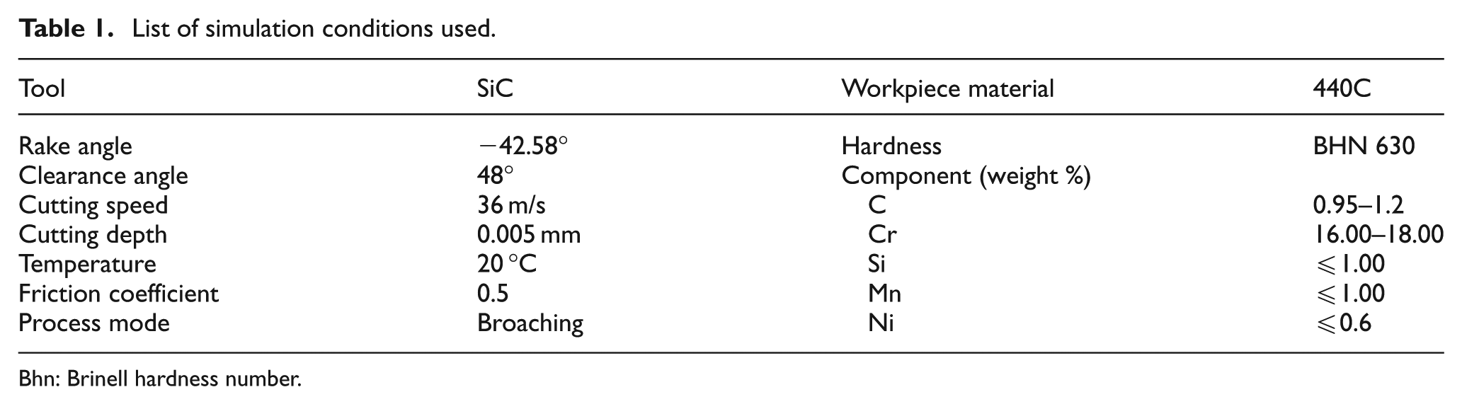
Bhn: Brinell hardness number.
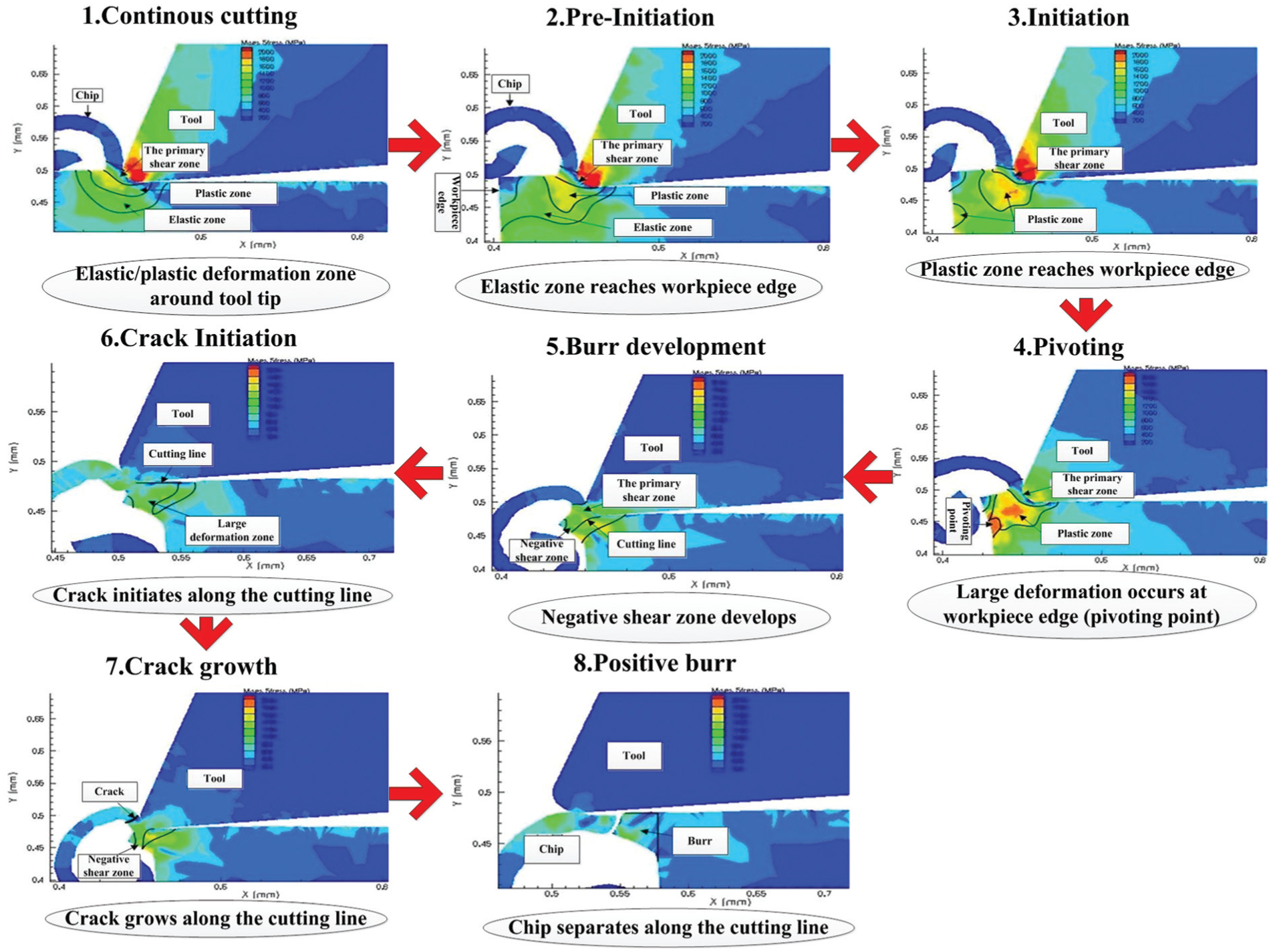
The schematic of burr formation.
Stage 1 describes continuous cutting with a flow type chip. And in stage 2, which is called pre-initiation, the deformation and stress distribution are affected by the workpiece edge. The elastic deformation zone appears as elastic bending or intersects at the workpiece edge. The plastic deformation zone around the primary shear zone also extends toward the edge. Burr initiation starts in step 3. The plastic deformation occurs at the workpiece edge as plastic bending. Both the primary shear zone and the plastic deformation zone around it extend. Step 4 describes pivoting. A large deformation occurs at the workpiece edge. A pivoting point can be observed where the large deformation is visually apparent. In stage 5, a negative shear zone develops. The burr develops, and the large deformation at the pivoting point expands to connect with the deformation in the primary shear zone. The large deformation under the cutting line is named the negative shear zone. As the tool moves toward the workpiece edge, the workpiece corner continues to pivot with the chip and the burr size increases. Stage 6 describes crack initiation for ductile materials. Since ductile materials have a large critical fracture strain, the crack initiates at the tool tip in the primary shear zone in a direction along the cutting line. The crack grows along the primary shear zone in stage 7. While moving along the cutting line, the tool not only leads to a growing crack but also makes the workpiece deform. As a result, the crack appears to grow along the cutting line. Stage 8 indicates the end of burr formation. The crack causes separation of the chip along the cutting line and a positive burr remains on the corner of the workpiece.
Micro-burrs scale variation
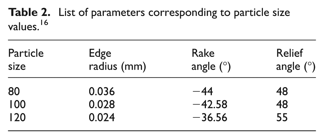
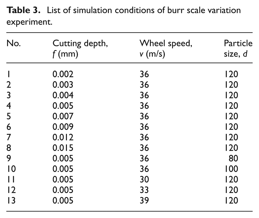
Grinding is a micro-cutting process conducted together by the whole effective abrasives of the wheel. Cutting action of tiny abrasives composing the wheel is the basis of grinding. The various physical phenomena in a grinding process can be explained by integrating the results of single grain cutting in the grinding area. Therefore, the cutting mechanism of single grit is important for the understanding of complex grinding mechanism. Furthermore, cutting depth could be considered invariant for face grinding; the diameter and the line velocity of grinding wheel are much higher than those of a workpiece. Therefore, the cutting trajectory of single grain relative to the workpiece can be regarded as a straight line, so that broaching is taken as the simulation model of end-face grinding. Meanwhile, edge radius, rake angle and relief angle could be determined according to the particle size values of the wheel. Based on the rotation speed and grinding depth, cutting speed and depth of broach were calculated. Table 2 shows the cutting parameters corresponding to different particle sizes, which was measured by a white light interferometer. 16 Table 3 shows the simulation conditions of the burr scale variation experiment. The measurement method of burr size is shown in Figure 4, and the depth of cutting in the figure is 70 µm.
List of parameters corresponding to particle size values. 16
List of simulation conditions of burr scale variation experiment.
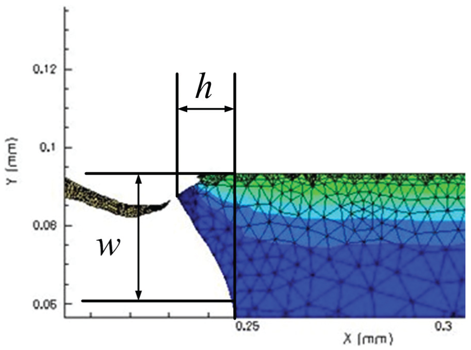
Measurement method of burr size.
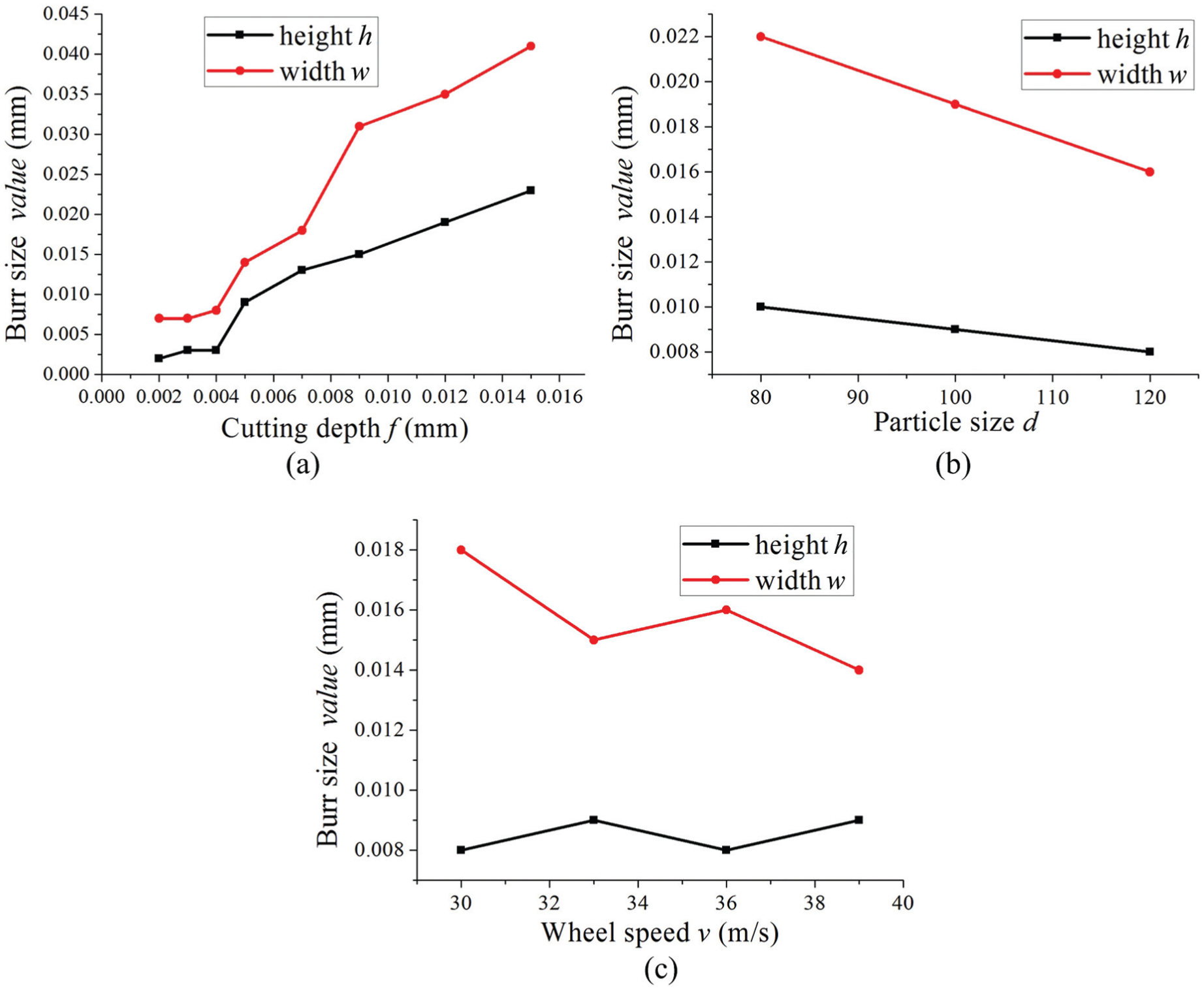
Figure 5(a) shows the evolution of burr size as a function of cutting depth (wheel speed v = 36 m/s, particle size d = 120). Both the width and height of burrs have an obvious rise with the increase in cutting depth. And by contrast, the width of burrs is always larger than the height. The reason for this phenomenon is that cutting heat and force both increased with the rise of cutting depth, plastic deformation region expanded accordingly and plastic flow of grinding face accelerated. Therefore, plastic protrusions launched by abrasives, namely, burrs, enlarged when the wheel lined to the end of the workpiece. Additionally, cutting layer rigid on the end of the workpiece declined with the increase in grinding depth, which may also lead to the enlargement of burrs.
Burr size under different simulation conditions.
Burr size under different particle sizes (wheel speed v = 36 m/s, cutting depth f = 0.005 mm) is shown in Figure 5(b). It is noticed that burr width and height both decline with the increase in particle size value. However, variation of width is more obvious than that of height by contrast. Since cutting edge radius and equivalent negative rake angle decreased accompanying the rise of particle size value, abrasives became sharper. Therefore, cutting heat and force of the grinding process got smaller, and plastic deformation zone decreased accordingly, which led to a smaller size of burrs.
Figure 5(c) illustrates that as grinding speed increases, the width of burrs has a declining trend, while the height of burrs essentially remain unchanged (particle size d = 120, cutting depth f = 0.005 mm). When the wheel speed increases, cutting heat of grinding enlarges and cutting force declines. Finally, both phenomena above lead to the inconspicuous change of burrs. Actually, the effect of cutting speed on burr size is complicated. However, in the processing of valve cores, higher cutting speed is still needed. With the increase in cutting speed, deformation of chips weakens, which leads to a decreasing possibility of burrs emerging.
Therefore, in order to control the size of burrs produced by grinding, under the permission of actual production, a smaller cutting depth, a grinding wheel with larger particle size and higher cutting speed must be selected. However, if the grinding depth is too small, the cutting layer may enter within the hardened layer of the material, and the plastic deformation in the chip will be more severe, resulting in a larger burr size. Also, in this case, the burrs are thinner and longer, which make the deburring process more difficult, hence it is required to make reasonable choices based on actual production.
Micro-burrs in deburring process
The micro-burr scale variation shows that in end-face grinding process, the grinding speed and the grinding depth as well as the grinding wheel specification have significant influence on the burr size. Apparently, the burr size develops linear to the depth of cut, that is, an increase in the depth of cut leads to an increase in burr size. By the simulation study of the laws of burr formation, optimized grinding process parameters are used for face grinding. A full understanding in the size of burrs after grinding provides the basis for deburring process.
The size of burrs is the most important parameter in the deburring process since the force needed to remove the burrs and the location accuracy of the tools are based on burr size. Burrs that are too big or small will cause problems to particular deburring methods, but the expected size of burrs will be obtained by applying the optimized grinding parameters. As is shown in Figure 6, some defects will occur on the working edge during the deburring process when the size of burrs reaches up to 0.08 mm, which means that the burrs have a higher hardening level and will cause defects when brittle fractures happen to burrs. In other words, according to the model of the burr formation obtained by the simulation analysis and the requirement of the face grinding process, the optimized parameters should be put into use in order to meet requirements. The optimized particle size value of the grinding wheel is 120, the linear velocity of the wheel is 36 m/s and the cutting depth is 0.05 mm.
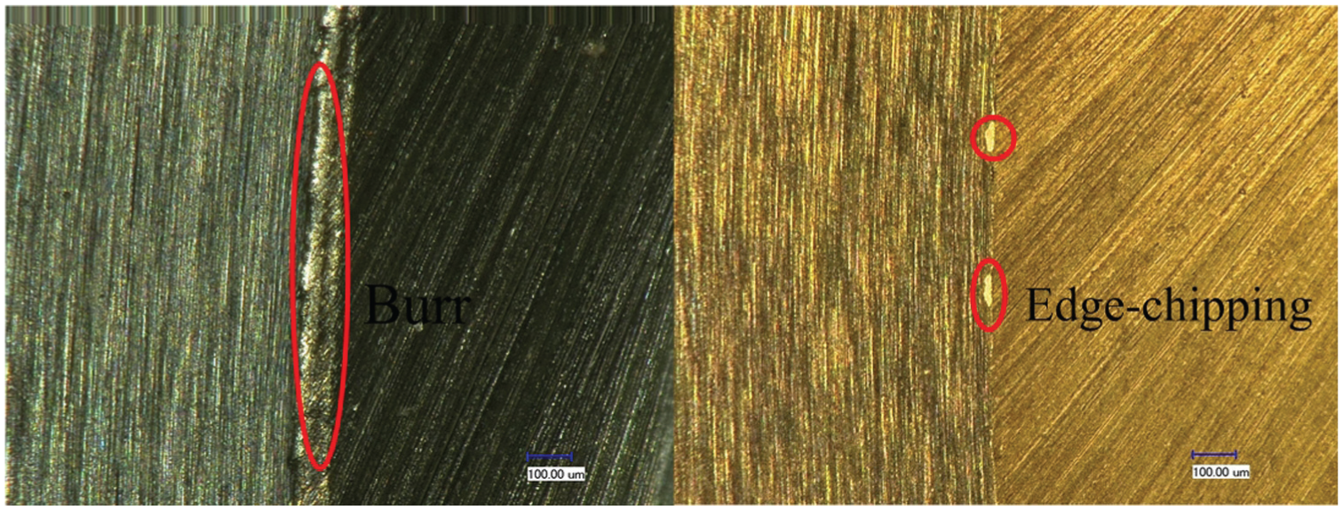
Defects of working edge after deburring process.
Automatic online micro-deburring method
Deburring with single-crystal diamond tool
For the online deburring method, the most important part is the choice of removal process and deburring tool. In this article, turning process and single-crystal diamond tool are introduced for online deburring of servo valve cores. Single point diamond turning is a processing technology by which nanometers of roughness and shape precision can be obtained. Therefore, the method chosen above fully meets the accuracy requirement. The edge radius of single-crystal diamond tool can reach to dozens of nanometers or below, and the sharp cutting edge is suitable for removing micro burrs. Since the deburring in this article is a finishing process and the burrs are very small, the temperature in the deburring process could be limited below the graphitization temperature at which huge damage may occur in the tool.
Using single-crystal diamond tool for deburring has the following advantages:
Electric spindle drive is not required in single-crystal diamond turning process, simplifying the structure, which makes it easy to ensure the machining accuracy. Electric spindle has complex structure, thus the vibration and heat generated by the motor operation will directly affect the spindle precision.
Single-crystal diamond tool has extraordinary wear resistance and sharp cutting edge, which can ensure the machining accuracy effectively.
In turning process, the primary motion is provided by rotating the workpiece and only linear feed motion is required for the tool, thus high stability can be achieved easily in this process.
The feed motion of the tool is linear and slow, and it is conducive for the realization of high precision tool setting using non-contact displacement sensors.
The weak rigid system, combined with the edge inclination angle of the cutting tool, will ensure complete removal of burrs without damaging the integrity of working edges.
Experimental verification
According to actual processing condition, using burr removing test platform which is shown in Figure 8, the online deburring method validation experiments are conducted. The grinding wheel is SiC wheel, particle size is 120, the linear velocity is 36 m/s and the cutting depth is 0.05 mm. The workpiece is servo valve core, the rotate speed is 180 r/min and the diameter is 10 mm. During deburring process, when the distance of the working edge and cutting edge of the single-crystal diamond tool reaches 0.1 mm, slow feed was used, and the feed rate of the cutting tool is 8 µm/s. Micro-deburring effect and wear condition of the single-crystal diamond tool were performed on Keyence VHX600 microscope.
Figure 7 illustrates the actual deburring process. Driven by the linear motors, accurate positioning of single-crystal diamond cutting tool and online deburring process were completed in cooperation with closed-loop control of the precise sensors. The end-face grinding process was conducted at the same time.

Micro-burr removing test platform and deburring process.
Figure 8 shows the actual deburring effect of the automatic online deburring method. The pictures of working edge are magnified 200 times. The burr on the undeburring edge after end-face grinding process has a height of 53 µm, which is a defect in micron size. After deburring, three detected positions of the working edge were sharp, no burr on working edge and fillet radius is less than 2 µm. In the last step, the match grinding equipment was used for working edge detection. The results show that the deburring method and the designed equipment can achieve anticipated goals and the accuracy, all meet the technical requirement.
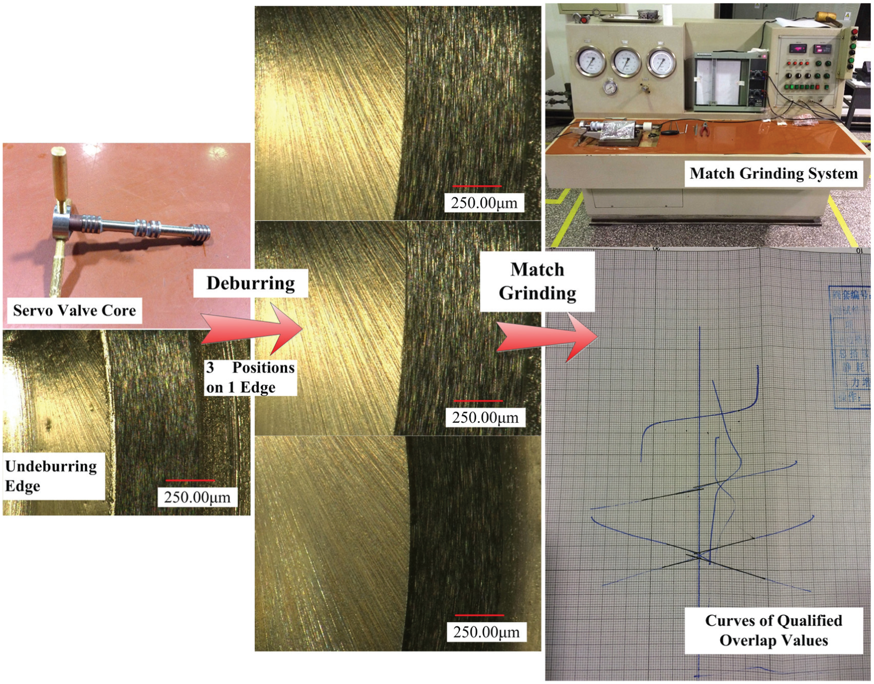
Deburring effect of micro-deburring.
By offline testing of the turning tool after deburring, using the measurement function by Keyence microscope, the tool wear can be obtained. Figure 9 shows that after deburring processes of 60 edges, a few micro-chippings were generated in individual parts of the rake face while none graphitization phenomenon has appeared. This micro-chipping is not caused by the deburring process but the radial run-out of the workpiece. The cutting edge of single-crystal diamond tools, which is brittle and sharp, will suffer certain impact due to the radial run-out of the workpiece, resulting in micro-chipping. But this will not affect the tool life, and the single-crystal diamond tool can be used repeatedly by being resharpened.
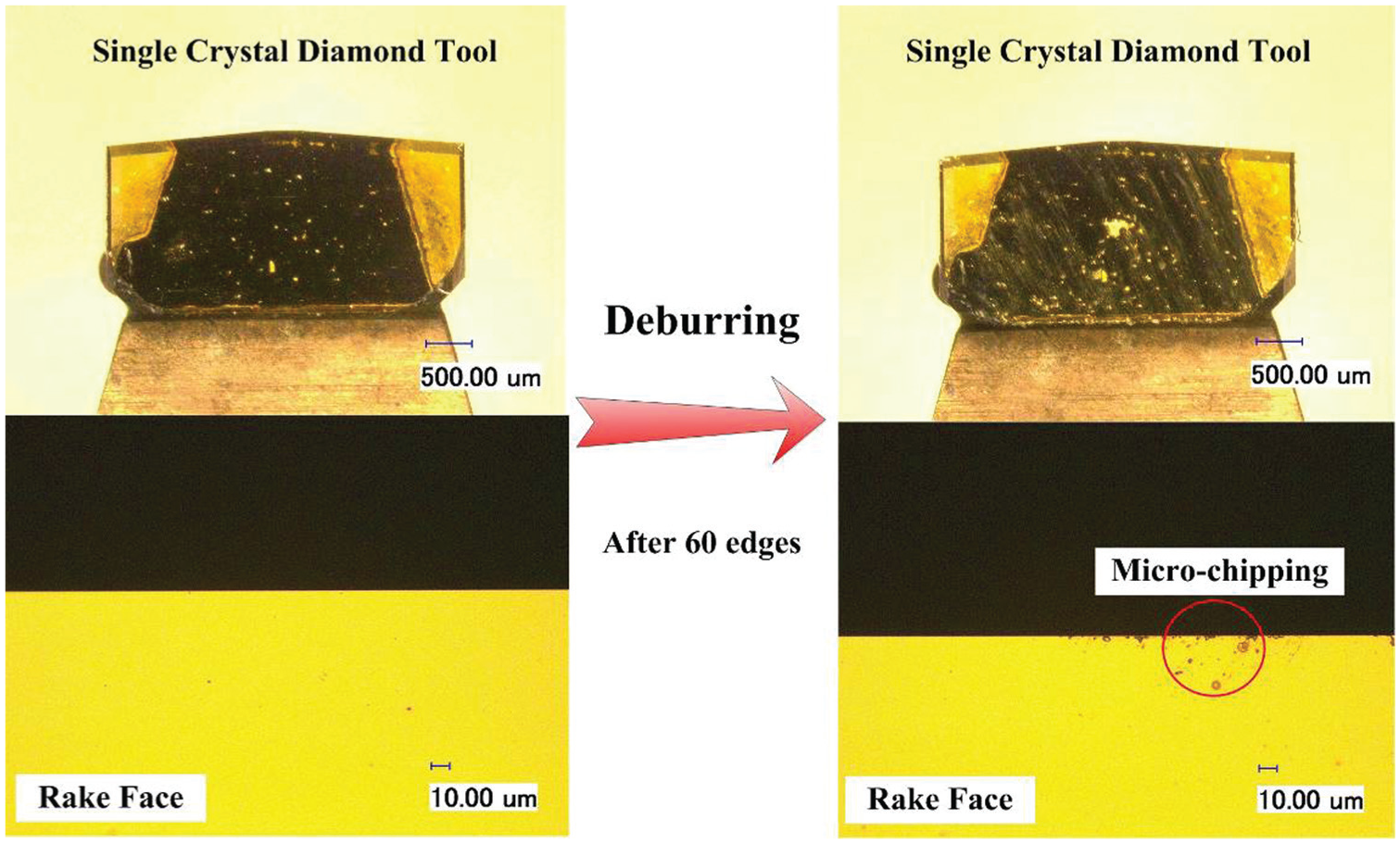
Wear condition of single-crystal diamond tool.
In short, the single-crystal diamond tool is effective for the deburring of the servo valve core edges. The deburring method is feasible.
Summary and conclusion
The sizes of micro defects are very close to the function sizes of precision parts. Therefore, the difficulty of deburring is extremely great. With a combination of simulations and experiments, a new automatic online deburring method is developed, which utilizes a precision motion control mechanism and effective deburring tools. Using this method, the burrs on the working edge can be removed effectively with high quality.
Burr formation process of servo valve core material 440C can be divided into eight stages, namely, continuous cutting, pre-initiation, burr initiation, pivoting, burr development, crack initiation, crack growth and burr formation. The simulation results show that in the end-face grinding process, the grinding speed and the grinding depth as well as the grinding wheel specification have significant influence on the burr size. Apparently, the burr size develops linear to the depth of cutting, that is, an increase in the depth of cut leads to an increase in the burr size.
Single-crystal diamond tool has extraordinary wear resistance and sharp cutting edge. Under the control of a precise feeding system, effective and complete removal of burrs can be achieved without damaging the integrity of the working edge.
Predictably, this automatic online micro-deburring method can be widely used in precision servo valve processing industry, which will greatly improve production efficiency and bring in massive economic benefits.
Footnotes
Declaration of conflicting interests
The author(s) declared no potential conflicts of interest with respect to the research, authorship and/or publication of this article.
Funding
The author(s) disclosed receipt of the following financial support for the research, authorship, and/or publication of this article: This work is supported by the National High Technology Research and the Development Program of China (2013AA040104) and the Key project of Shanghai Jiao Tong University (YG2012ZD07).