
Abstract
End milling of the curved surfaces is characterized by significant amount of engagement variation along the tool path which results in deflection-induced surface error on the machined components. Feed rate regulation cannot be used in this case to minimize the surface errors as it necessitates continuous change in feed rate along the tool path which deteriorates surface finish and lowers productivity. Another approach in the form of tool path modification scheme was also proposed in the literature to minimize engagement variation at corners of a pocket. This approach has been effective in reducing fluctuations of engagement at corners and cannot be applied directly in machining of curved geometries where engagement variation is continuous along the entire tool path. Keeping these limitations in focus, a new methodology is proposed in this article to minimize surface error variation that modifies machining strategy for the curved components. The strategy proposes machining of the curved components into two different stages: first, generating the modified semi-finishing geometry using algorithm proposed in this article and then producing the desired geometry using conventional contour parallel tool path. The methodology generates the modified semi-finishing geometry such that the engagement offered is constant when a finishing pass is made. The effectiveness of the proposed methodology has been verified by performing computational studies and machining experiments on typical curved geometries. It is observed that the proposed methodology is quite effective in minimizing the variation in the surface error on the machined components.
Introduction
End milling of curved geometries is gaining considerable importance in aerospace, automobile and die/mold manufacturing industries due to increased aesthetic requirements and complex functional specifications of the machined components. In machining of these geometries such as wing sections, impellors and molds, finishing operation is performed using ball end mill. Prior to finishing operation, large amount of the material is removed from a stock by 2½D roughing which transforms bulk raw material close to its final shape at higher productivity using flat end mill. 1 This operation involves contoured tool path in XY plane combining X- and Y-axis motions along the desired geometry which is also known as contour parallel tool path. 2 Such a tool path is completed in XY plane at constant axial depth of cut, followed by axial plunging and then following the same or different tool path in XY plane again. In many of these cases, large overhang of end mill is inevitable due to specific dimensional and geometric characteristics of the components to be machined. These circumstances using large overhang of cutter pose problems with contour parallel tool path due to significantly varying cutter–workpiece engagement. The variation in engagement results in change in instantaneous cutting forces along the tool path which is further transformed in the form of cutter deflection–induced surface errors on the machined components.
As the depth of cut in ball end milling operation is very small, uneven surface error left on the semi-finished component causes fluctuation of cutting forces during finishing operation and thereby results in poorly machined components. Therefore, it is desirable to have minimum surface error variation on the semi-finished components. The engagement angle in 2½D end milling is the amount of angular rotation of the cutter for which it is in contact with the workpiece. As milling is an intermittent cutting process, cutting tooth and workpiece are in partial engagement with each other. Figure 1 shows the variation in the engagement angle in 2½D end milling for various workpiece geometries.
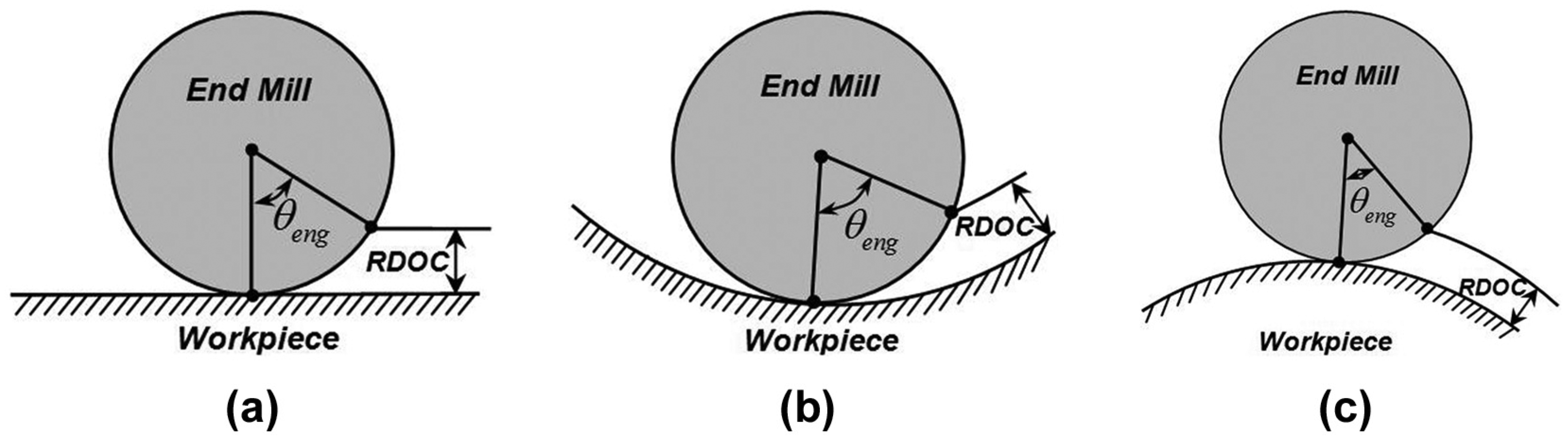
Engagement angle for various geometries: (a) straight geometry, (b) concave geometry and (c) convex geometry.
Three different cases commonly encountered in end milling operation are shown in Figure 1: linear or straight segment, concave arc and convex arc. Depending on the variation in workpiece curvature along the tool path, two variations in curved geometries exist: constant curvature or circular geometries where workpiece curvature is invariant and variable curvature geometries where workpiece curvature varies continuously along the tool path. The engagement angle is defined using radial depth of cut (RDOC) and radius of cutting tool (r) in machining of straight geometries. The procedure to determine the engagement angle in case of circular geometries requires radius of workpiece in addition to RDOC and r. Mathematical formulations determining the engagement angle during constant curvature geometries can be found from the studies made by Bera et al. 3 During machining of variable curvature geometries, workpiece curvature varies continuously along the tool path leading to fairly non-trivial procedure for computation of the engagement angle. Rao and Rao 4 developed mathematical formulations that predict the variation in the engagement angle along the tool path while machining variable curvature surfaces. It can be clearly seen from Figure 1 that the engagement angle varies significantly with the change in workpiece geometries. The engagement angle is fairly higher in case of concave geometries while it is least in case of convex geometries for the same RDOC and r. In case of complex curved geometries where curvature variations are continuous in nature, engagement too varies considerably along the tool path. This article attempts to develop a methodology to regulate inherent variation in the engagement angle during the final pass by preemptive compensation of the tool paths during previous passes.
Previous work
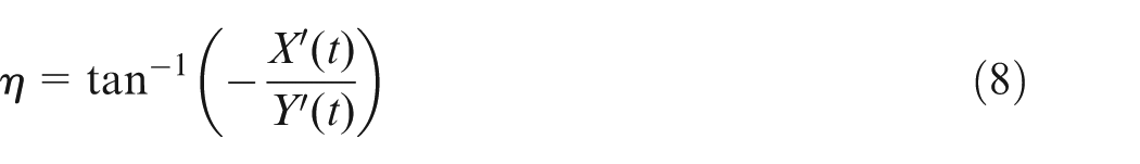
The problem of varying engagement along the tool path was addressed by various researchers during end milling of pockets and a number of alternatives were sought to minimize its consequences. Many researchers recommended use of feed rate regulation to control increased engagement. Kramer 5 proposed an algorithm to regulate feed rate during machining of a convex pockets. Kloypayan and Lee 6 studied material removal characteristics of various end mill shapes in machining straight and circular portions of a pocket. This study demonstrated that the material removal rate changes significantly with the geometry and feed rate regulation can be used effectively to compensate for the change in engagement. These studies mainly focus on the geometrical aspects of the milling process and process physics is not considered in regulation of feed rate. Ko et al. 7 developed virtual machining system that integrated process physics while generation of the tool path by predicting cutting force and tool deflection–induced surface errors during machining of a pocket. The system generated the modified feed rate values for a computer numerical control (CNC) program based on the magnitude of the surface error predicted from computational models. The successful implementation of adaptive feed rate regulation requires sophisticated servo controllers possessing rapid acceleration and deceleration characteristics facilitating frequent and quick change in feed rate. It is not advisable to change feed rate frequently in many instances as it deteriorates surface finish of the machined components. Also, the machine tool may not be operating at its full potential whenever feed rate regulation is used and productivity of machining operation is lowered.
Some researchers suggested modification of the tool path or change in machining strategies to minimize the variations in engagement during end milling operation. Choy and Chan 8 showed that the cutter load increases severely during machining concave corners of a pocket due to an increase in cutter swept angle while using contour parallel tool path. It results in poor surface quality and increased possibility of cutter breakage. The surface quality was improved by addition of bow-like looping segments at the corners to remove the material in several passes. Hinduja et al. 9 showed that the cutter diameter can also influence engagement variation during machining of pockets. It was demonstrated that the engagement variation is noteworthy for larger diameter cutters and use of smaller diameter can help in reducing engagement variation. Kim and Choi 10 compared performance of three different tool path strategies in machining of irregular-shaped pockets to minimize machining time and showed that the zig-zag strategy is ideal while machining irregular-shaped pockets. Lin et al. 11 examined the effect of direction parallel and contour parallel tool path strategies on accuracy of the curved components. The study showed that the use of iso-scallop tool path strategy can minimize machining error significantly in comparison to strategies available in commercial computer-aided design (CAD)/computer-aided manufacturing (CAM) software. Hsieh and Chu 12 showed that the control of machining error in five-axis flank milling is quite a difficult task and requires systematic approach such as particle swarm optimization over the existing ad hoc approaches such as surface ruling and tilting cutting tools at certain angle. Vessaz et al. 13 demonstrated the importance of selecting proper tool path while end milling of two-dimensional (2D) blades. It was highlighted that the selection of improper tool path will result in significant surface error on the turbine blades and quite different hydraulic properties. Ferreira and Ochoa 14 presented a methodology to generate the tool path for 2½D milling of pockets considering different diameters of cutting tools, concept of medial axis and pixel-based simulation. It was observed that the proposed approach reduces problematic machining regions greatly and improves process performance. Recently, Pavanaskar et al. 15 proposed use of digital micrography while generating energy-efficient tool paths in 2½D pocket machining. It has been shown that the use of the proposed strategy results in significant savings in the energy consumed during roughing operation. The tool path modification approach or change in machining strategy proposed in the above studies is considered effective as it does not require sophisticated hardware for its implementation.
In addition to research attempts discussed above which are primarily focused on determining ideal machining strategies for pockets or contours, attempts were also made to modify the tool path such that the surface error due to cutting force–induced deflection is minimized. Suh et al. 16 developed virtual machining simulator that converts nominal CNC program generated from CAM software into a modified program based on cutting force and cutter deflection models. The methodology uses the mean surface error computed from the deflection models as a basis to generate the modified tool path. This tool path is used further in milling operation which reduced the surface error significantly. Cho and Seo 17 used radial basis function–based artificial neural network (ANN) and later 18 polynomial function–based ANN to determine the mean surface error in the presence of tool deflections. The modified tool path was generated using the mean surface error predicted from these models which produced components with improved dimensional accuracy. An important aspect that was not incorporated in tool path modification schemes discussed so far is the axial variation in the surface error which is an unavoidable characteristic of an end milling operation performed in the presence of tool deflections. Dépincé and Hascoët 19 showed that the axial variation in the surface error is highly non-linear and it is crucial in deciding the effectiveness of compensation scheme. The axial variation in the surface error was correlated with machining tolerances in this study and a hybrid approach was presented to meet tolerance requirements on the finished components. These research attempts obtained the modified tool trajectory on the basis of the surface error predicted from computational models. Therefore, the effectiveness of tool path compensation scheme solely relies on prediction accuracy of the elements involved in surface error model.
In order to avoid the need of sophisticated computational models in predicting the surface error, the concept of maintaining constant engagement along the tool path was introduced by Stori and Wright. 20 The approach divided the tool path in a series of segments and determined the engagement angle at each location along the tool path. Later, the position of tool center at each segmented location was changed such that the engagement angle was regulated at a desired level and the modified tool path was obtained. Uddin et al. 21 highlighted one of the major drawbacks of this algorithm and showed that the approach can be applied to roughing operations only. If finished tool path trajectory is modified, it no longer generates the desired geometry and leaves over-cut or under-cut on the machined surface. Keeping this limitation in focus, a new methodology was proposed by Uddin et al.1,21 that modifies the semi-finishing tool path during machining of pockets such that the engagement is regulated during the finishing pass. The methodology was used to regulate engagement while machining pockets containing concave and convex circular arcs of different radii and significant improvement in the surface error was obtained. As the approach considers circular geometry in the study, the modification of the tool path is required only at transitions joining circular arcs of different radii. The study focused on improvement of the mean surface error along the tool path only and the axial variation in the surface error was not addressed. It has been observed in recent studies 22 that the axial variation in the surface error can also change due to the change in radial engagement during machining of curved geometries. The primary reason for the axial variation in the surface error with cutting conditions is the change in instantaneous cutting force profile and its relationship with the exit pattern of cutting flute in the presence of tool deflections. 22 Such varying nature of surface error profile with workpiece curvature is a major bottleneck for process planners to strive for enhanced machining productivity and accuracy. In such a situation, regulation of engagement along the tool path becomes a valuable tool that generates uniform tolerances on the machined components. This article presents an algorithm to regulate engagement variation along the tool path during machining of variable curvature geometries. The results of the proposed methodology are also corroborated with the machining experiments conducted on representative curved geometries.
It is important to note that the terminology finishing and semi-finishing pass is used here in different context than the earlier literature. The term finishing pass indicates the final pass of roughing operation while the semi-finishing pass indicates a pass prior to the final pass of roughing. The same terminology has been adopted further in this article. Henceforth, the article is organized as follows; section “Constant engagement tool path algorithm” discusses an algorithm to generate constant engagement tool path during machining of curved geometries. The developed algorithm is implemented in the form of computer simulations to assess the effectiveness of the developed methodology. Section “Computational results and experimental validation” summarizes the results of computer simulations and the machining experiments on typical curved geometries. The article concludes with summary of contributions made from this work in section “Conclusion.”
Constant engagement tool path algorithm
The primary objective of the constant engagement tool path algorithm is to change the tool trajectory corresponding to the semi-finishing pass such that the engagement angle is regulated at the desired level during the finishing pass. This requires determination of a variable offset curve with reference to the curve representing finished workpiece geometry such that the engagement is regulated at the desired level when a finishing pass is made. The parametric equation of a 2D planar curve corresponding to the finished workpiece trajectory and corresponding contour parallel tool path to produce the same can be given using equations (1) and (2), respectively

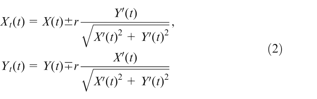
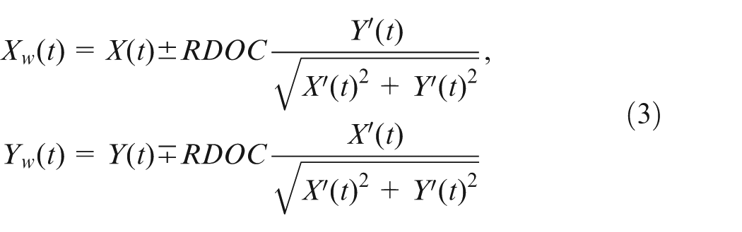
The contour parallel workpiece trajectory generated during the semi-finishing pass can be described using equation (3) as an offset curve corresponding to the finished workpiece geometry in equation (1)
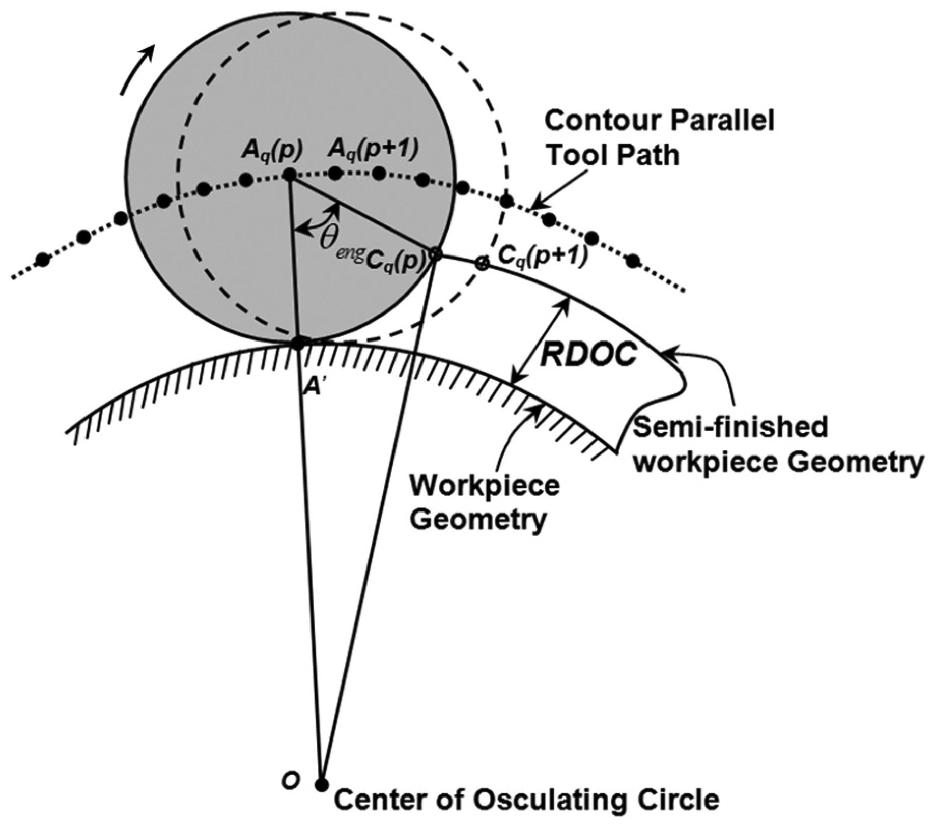
End milling of variable curvature surface using contour parallel tool path.
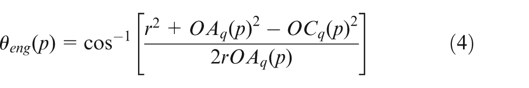
The procedure to determine the engagement angle for each tooth requires dividing tool trajectory into discrete segments with length equal to feed per tooth. Figure 2 shows two successive tool center positions Aq(p) and Aq(p + 1) at a distance equal to feed per tooth along tool center trajectory presented in equation (2). These locations represent instances at which successive teeth enter into the cut. Here, p refers to each discrete location along the tool path and it varies from 1 to N while the subscript q refers to individual machining pass of roughing operation and it varies from 1 to q with qth pass referred as a final pass. Also, Cq(p) and Cq(p + 1) are tooth entry points corresponding to two successive tool center positions Aq(p) and Aq(p + 1), respectively, in down milling. O is the center of osculating circle corresponding to point A′ on finished workpiece geometry. Once the tool path is divided into discrete segments, the engagement angle corresponding to a tool center position Aq(p) can be determined using cosine rule as equation (4)
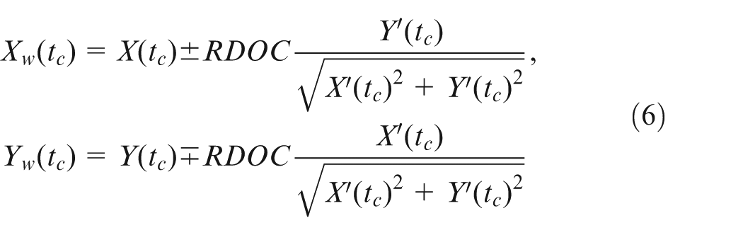
When tool center is at Aq(p), the intersection point of cutting tool circumference and semi-finished workpiece trajectory can be computed by solving equations (5) and (6) which can be termed as tooth entry point Cq(p)

Similarly, the engagement angle for other tool center locations can also be computed. Using equations (1)–(6), the locations of tool center point and tooth entry points corresponding to contour parallel tool path can be obtained.
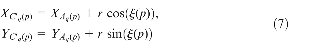
The primary objective of the proposed algorithm is to determine the modified location of tooth entry point C′
q
(p), corresponding to pth tool center position along the tool path such that the engagement angle is modified from
Step 1: use equation (1) of workpiece geometry and derive mathematical formula for contour parallel tool path as equation (2). The contour parallel tool path has to be divided into discrete segments with length equal to feed per tooth. The discrete positions of tool center are identified as Aq(1), …, Aq(p), … to Aq(N) and shown in Figure 3(a).
Step 2: compute intersection point between tool circumference and semi-finished workpiece surface such that the engagement at each discrete position of the cutting tool is regulated at the desired level (
Here,
Step 3: the procedure discussed in Step 2 has to be repeated along the entire tool path to obtain the desired intersection points C′ q (1), …, C′ q (p), … to C′ q (N). These points are imported to the CAD/CAM software to generate the modified workpiece surface. The modified workpiece surface is variable offset curve to the finished workpiece geometry which offers constant engagement during the finishing pass.
Step 4: the tool path for the modified semi-finished workpiece surface is generated by offsetting the curve generated in Step 3 by amount r.
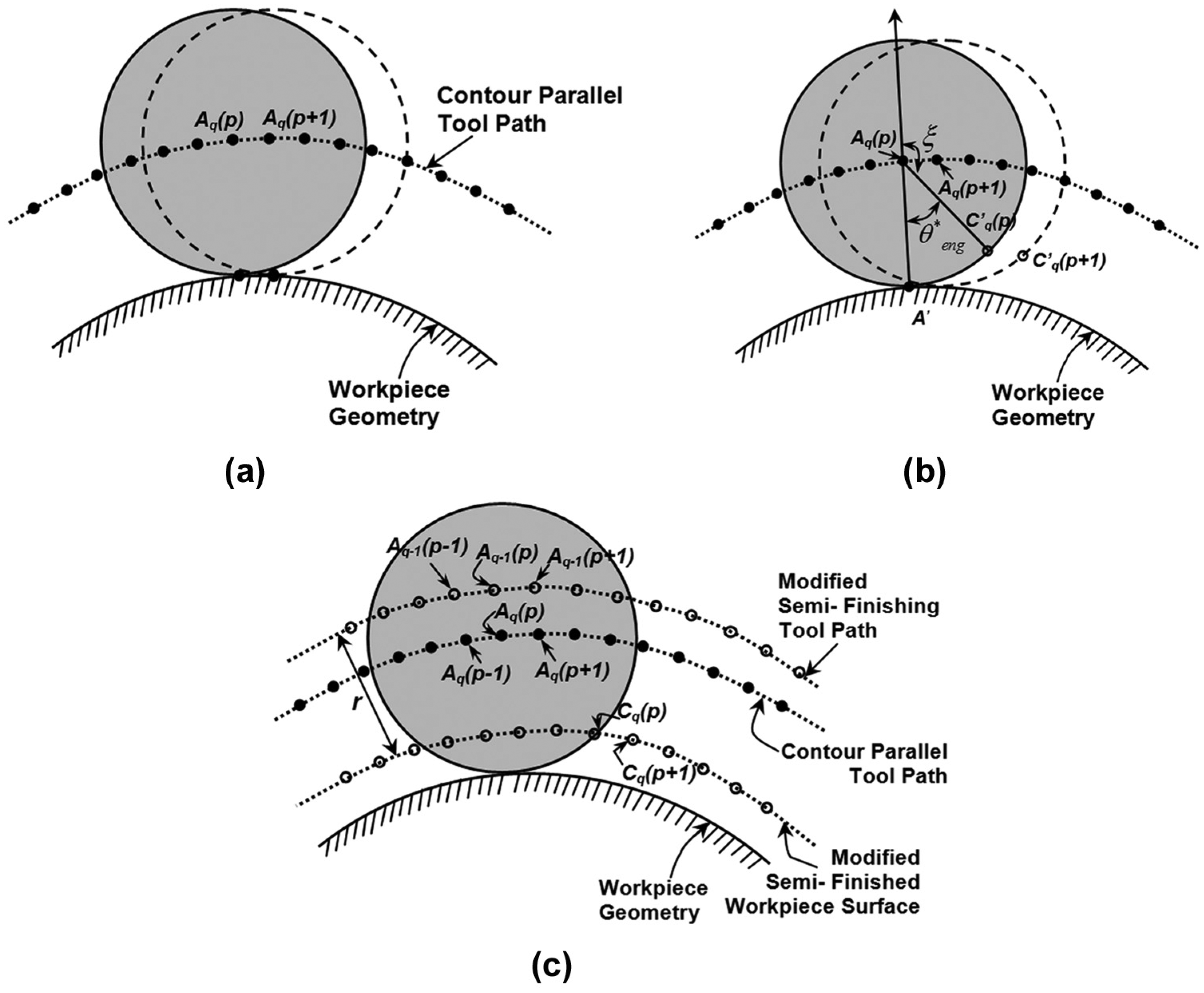
Constant engagement tool path in milling of curved geometries: (a) contour parallel tool path, (b) determination of modified intersection point and (c) generation of semi-finished workpiece surface and tool trajectory.
Figure 3(c) schematically shows the modified workpiece surface obtained using the proposed methodology, the tool path to generate semi-finished surface and contour parallel tool path. The proposed methodology outlined above has been implemented in the form of a computational program to generate the modified tool path for curved geometries and the results for representative case are summarized in the next section along with the experimental results.
Computational results and experimental validation
The algorithm developed in the previous section has been implemented in the form of a computational model to generate the modified semi-finished workpiece geometry and the corresponding tool path that regulates engagement at the desired level while machining curved geometries. The simulation program needs parametric equations of the finished workpiece geometry, cutting conditions and desired engagement angle as the inputs and generates coordinates of the variable offset semi-finished workpiece geometry as the output. The variable offset semi-finished workpiece geometry generated using the developed model regulates the engagement angle at the desired level along the tool path during the final pass of roughing operation. The coordinates generated using simulation program have been imported to the CAD/CAM software for generation of the semi-finished workpiece surface. A set of roughing tool paths to obtain the semi-finished workpiece geometry have been generated by offsetting newly generated workpiece surface. The details of tool path generation and its effect on machining accuracy are discussed in subsequent sections using illustrative examples.
Illustrative examples
To appreciate the effectiveness of the developed constant engagement tool path algorithm in end milling operation, an illustrative example of machining two different variable curvature geometries is considered. The first geometry chosen in this study is an elliptic arc in its concave form while the other one is its convex counterpart and are shown in Figure 4. This section presents the results of computational studies and machining experiments in regulating cutting engagement along the tool path for both these geometries. It has to be noted here that the desired engagement angle (

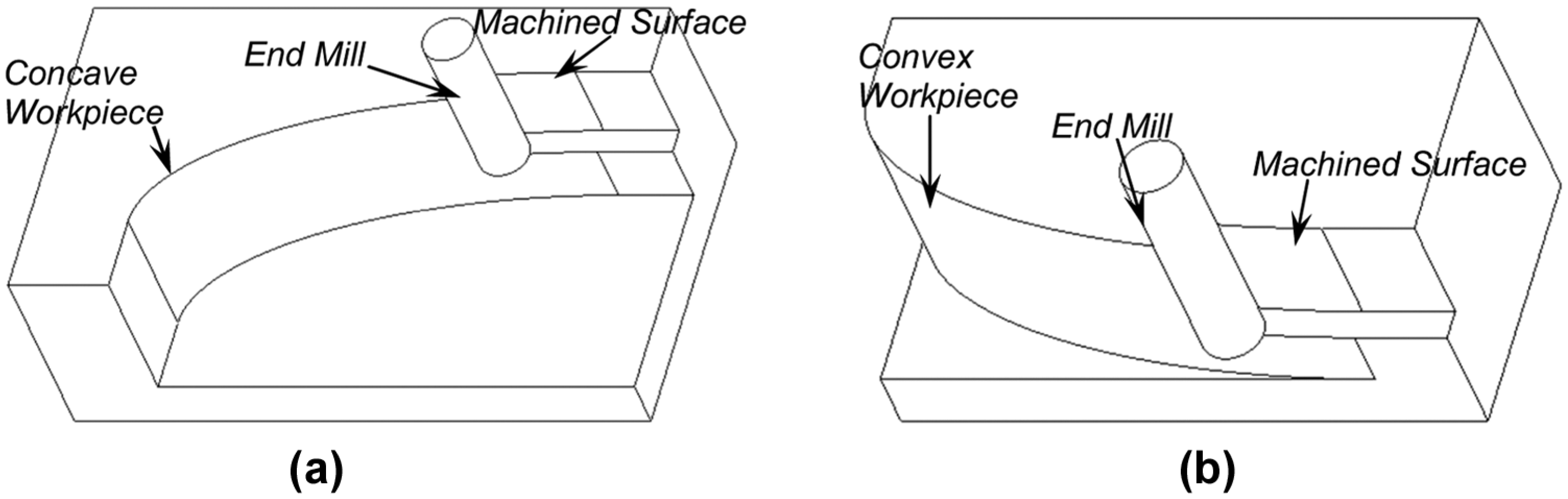
Representative workpiece geometries: (a) elliptical concave geometry and (b) elliptical convex geometry.
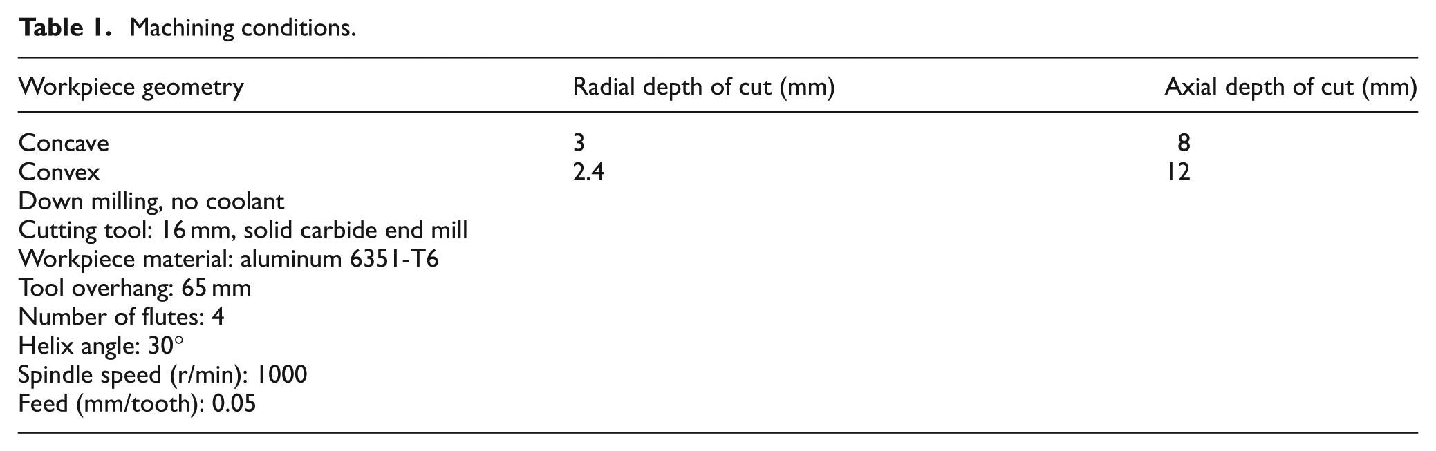
Machining conditions.
The values of a and b in equation (9) are chosen as 80 and 30 mm, respectively, during this study. The next section discusses the results of computational studies and machining experiments for representative workpiece geometries.
Results and discussions
The tool path modification algorithm proposed in section “Constant engagement tool path algorithm” has been used to regulate engagement during end milling of the representative curved geometries. Figure 5(a) and (b) shows workpiece geometry generated using the proposed algorithm which is a variable offset curve offering constant engagement during the final pass. These figures also show contour parallel workpiece geometry for representative cases. The procedure begins with computation of the engagement angle from low-curvature region marked as A and moves into high-curvature region with the progress of cut which is marked with an arrow in Figure 5(a) and (b). The magnified view of contour parallel workpiece geometry and modified geometry obtained using the proposed algorithm is also shown in Figure 5(c) and (d). It can be seen that the modified workpiece geometry obtained using algorithm shifts toward finishing geometry while machining concave arc. On the contrary, the modified workpiece surface goes farther from the finished workpiece surface in case of convex arc. The effective result of such a shift is to regulate cutting engagement at the desired level during the finishing pass.
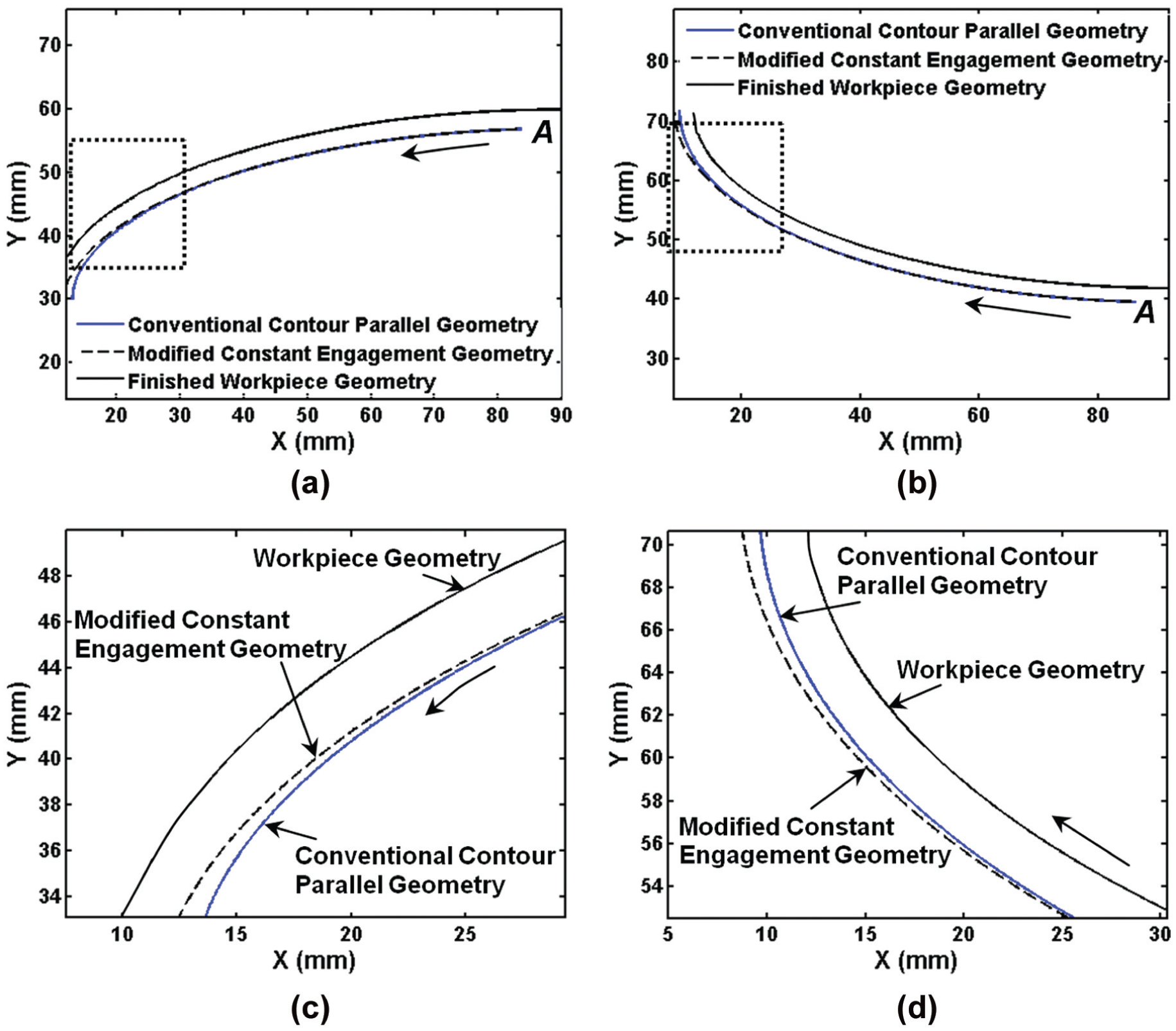
Application of proposed algorithm for representative geometries: (a) conventional and modified concave geometries, (b) conventional and modified convex geometries, (c) magnified view of (a), and (d) magnified view of (b).
Figure 6(a) and (b) shows the variation in the engagement angle along the tool path during machining of concave and convex geometries, respectively. It is evident from the results that the contour parallel tool path offers significant amount of variation in the engagement angle. But constant engagement tool path proposed in this article regulates engagement variation effectively at the desired level. It can be seen that the engagement angle is maintained at a constant level along the entire finishing pass after applying tool path modification algorithm in case of both geometries. From the results presented in Figure 6(a) and (b), it can be concluded that the proposed approach eliminates engagement variation due to workpiece curvature while machining curved geometries. It results in a machining situation similar to straight and circular geometries where engagement is invariant along the entire tool path. As the desired engagement angle along the tool path is calculated on the basis of limiting cutting forces and surface error, the semi-finishing workpiece trajectory offering constant engagement during the finishing pass can be generated using the proposed algorithm.
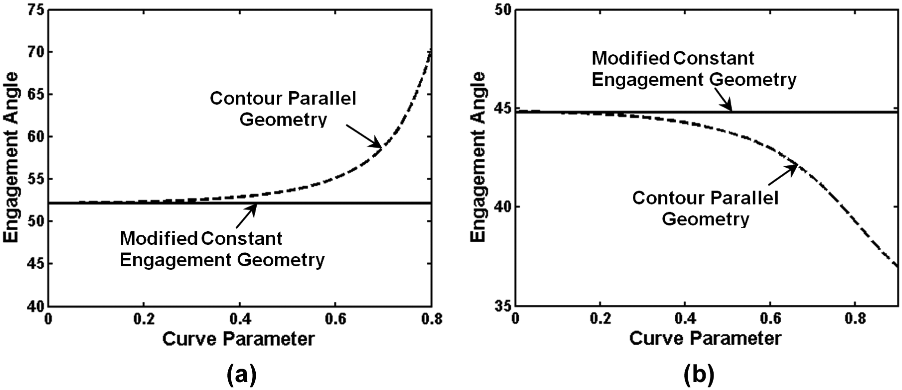
Engagement variation for representative geometries: (a) concave geometries (b) convex geometries.
The strategy proposed by Uddin et al.1,21 modifies the semi-finishing tool path only and preserves all other passes as contour parallel during roughing operation. This methodology can only be applied while machining circular contours as engagement varies at transition points only, that is, the geometry changes from concave to convex and vice versa. If other roughing passes are maintained contour parallel and only the semi-finishing pass is changed for variable curvature surfaces, considerable amount of variation in engagement can be encountered during the semi-finishing pass which results in uneven cutting forces. This problem does not prevail while using the proposed methodology as it generates the modified variable offset curve in the form of the semi-finished workpiece surface and other roughing passes are parallel to the geometry generated using the proposed algorithm. However, the final pass generating the finished workpiece geometry is contour parallel tool path as it preserves the shape of the machined component.
Experimental results
A set of the machining experiments and surface error measurements are conducted on curved geometries to substantiate the effectiveness of the algorithm proposed in earlier section. The machining experiments are conducted on a CNC vertical milling machine for representative concave and convex geometries. To illustrate the potential of the developed methodology in minimizing surface error variation, two different machining strategies are considered for the experiments. The first strategy represents application of contour parallel tool path for each pass, that is, roughing and finishing. The part programs are generated using contour parallel tool path option commonly available in the CAD/CAM software for roughing and finishing passes. The second strategy represents application of the proposed methodology while generating the tool path during machining of curved geometries. The modified workpiece surface is produced using the semi-finishing passes generated using the algorithm proposed in section “Constant Engagement Tool Path Algorithm” and part programs corresponding to roughing and semi-finishing operations are generated from the CAD/CAM software. The final pass is still contour parallel tool path as it preserves the shape of the finished workpiece geometry. Table 1 summarizes cutting conditions used in machining tests. The values of cutting forces in each machining experiment are recorded using Kistler 9272 dynamometer. The dynamometer records cutting forces in X- and Y-directions which have been resolved to obtain resultant or total cutting force (
Figure 7(a) and (b) illustrates comparison of the average cutting force along the finishing pass when components are machined using both strategies. The force values shown in Figure 7(a) and (b) are the average values of the resultant cutting force during each cutter revolution. It can be seen that the force level is uniform along the entire tool path when the proposed strategy is used in machining of curved geometries. But in case of contour parallel tool path, cutting force increases with workpiece curvature as observed in earlier studies on curved geometries.4,18 When contour parallel tool path is used in machining of concave geometries, cutting force increases along the tool path with workpiece curvature. The peak value of the average cutting force is 260 N corresponding to the highest workpiece curvature location on workpiece geometry. Meanwhile, the average cutting force value for the same location is 210 N when the modified strategy of regulating engagement along the tool path is used. In case of convex geometries, exactly opposite happens and cutting force reduces with workpiece curvature when contour parallel tool paths are used. But the force levels are constant along the entire tool path when the proposed algorithm is used.
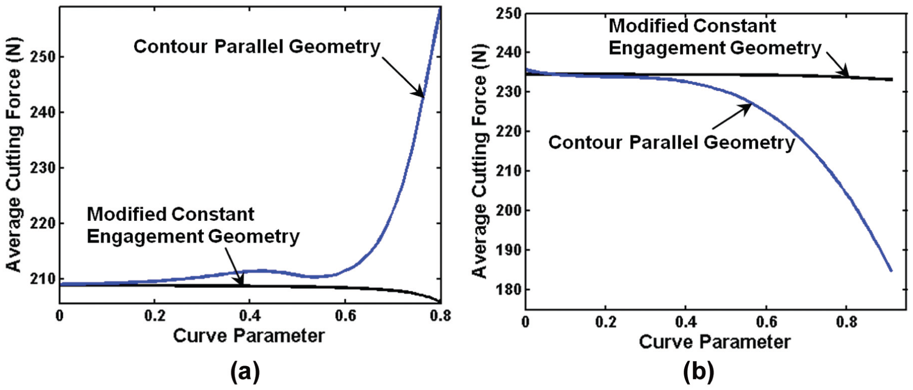
Comparison of cutting force variation between machining strategies: (a) concave geometries and (b) convex geometries.
Figures 8 and 9 show the variation in the surface error for concave and convex geometries, respectively, measured after performing the machining experiments using both strategies. Figure 8(a) shows the variation in the surface error for concave geometry when it is machined using contour parallel tool path. Surface error variations are studied along the axial direction as well as the length of the machined component. The results show that the axial variation in the surface error is not uniform along the length of component and its shape changes with workpiece curvature. The surface error profile is invariant for certain length of workpiece, but it changes after some time. With further increase in workpiece curvature, the change in error profile is prominent and the location of minimum error starts shifting downward from the top. The surface error profile no longer conserves its shape from this point onward and transforms into the another shape containing “kink” in the profile. Such change in surface error profile along the tool path is mainly due to the variation in engagement pattern of cutting flutes in the presence of workpiece curvature. The detailed explanation for the variation in axial profile of the surface error along the tool path can be found from the studies of Desai and Rao 22 which discusses surface generation mechanism for curved geometries in the presence of cutter deflections. Figure 8(b) shows surface error variation when the same geometry is machined using constant engagement tool path presented in this article. It can be seen that there is no change in the axial variation in the surface error and it is uniform along the entire tool path. Although workpiece geometry is same in both cases, cutting engagement is identical along the tool path when the proposed approach is used which modifies the semi-finished workpiece geometry. As cutting engagement is invariant along the tool path, the engagement pattern of cutting flutes does not change as previous case and the change in surface error profile is not seen.
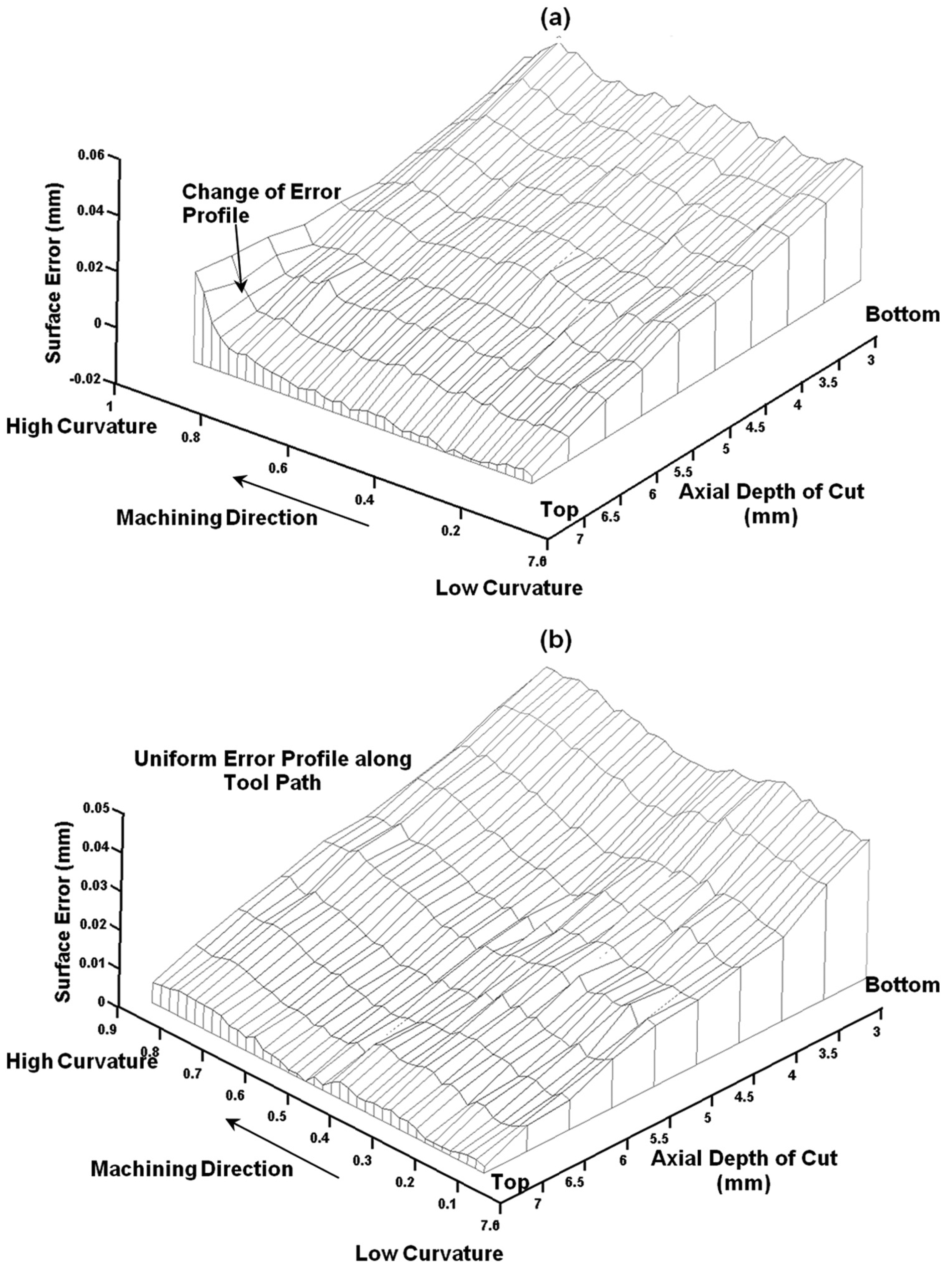
Comparison of surface error variation in concave geometries: (a) contour parallel geometry and (b) constant engagement geometry.
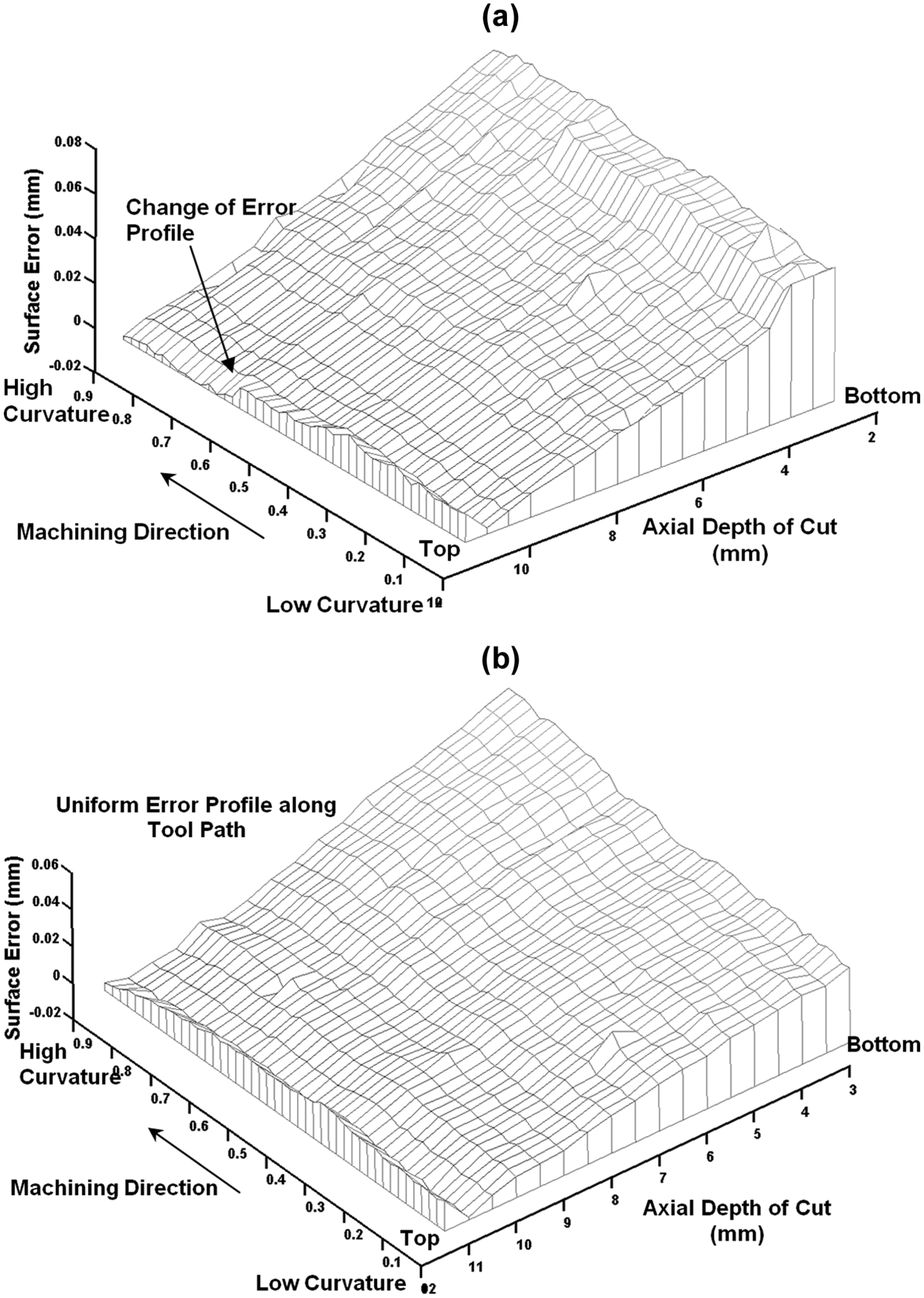
Comparison of surface error variation in convex geometries: (a) contour parallel geometry and (b) constant engagement geometry.
Figure 9(a) depicts the variation in the surface error in machining of convex geometries when it is machined using contour parallel tool paths. Once again the axial variation in the surface error is not identical along the tool path due to the presence of workpiece curvature and change in radial engagement. At the beginning of the cut, surface error profile contains “kink” at the top of workpiece surface which disappears later due to reduction in engagement. Figure 9(b) shows surface error variation when the same geometry is machined using constant engagement approach presented in this article. It can be seen that the proposed methodology eliminates the variation in the surface error resulting due to workpiece curvature. The axial variation in the surface error is uniform along the entire tool path. As radial engagement is maintained at the same level along the tool path, the change in surface error profile is not seen in the results. The proposed methodology eliminates workpiece curvature effects and results in machining situation similar to straight or circular geometries.
Conclusion
This article presents a methodology to minimize the axial variation in tool deflection–induced surface error during machining of curved geometries. The study shows that the use of contour parallel tool path results in significant variation in engagement along the tool path and uneven surface error on the machined components. This article presents an algorithm to modify the semi-finished workpiece surface such that the engagement along the finishing pass is regulated at the desired level. The methodology requires parametric equations of the finished workpiece geometry, cutting conditions and desired engagement angle along the tool path as the input. It generates the modified semi-finished workpiece contour in the form of a variable offset curve which can be the input to the commercial CAD/CAM software for obtaining the tool paths. The methodology generates roughing and semi-finishing tool paths using the modified workpiece geometry obtained from the algorithm while the finishing pass is still contour parallel as it preserves the shape of the workpiece. The application of the developed algorithm has been demonstrated on typical concave and convex workpiece geometries. The effectiveness of the proposed scheme was also substantiated through a set of machining experiments which showed good agreement with its predicted counterparts. The outcomes of the article showed that the developed methodology has great potential to reduce the axial variation in the surface error in machining of curved geometries without developing computational models predicting surface error and compromising productivity.
Footnotes
Appendix 1
Declaration of Conflicting Interests
The author(s) declared no potential conflicts of interest with respect to the research, authorship and/or publication of this article.
Funding
The author(s) received no financial support for the research, authorship and/or publication of this article.