
Abstract
Electronic systems are prone to failures, whether during manufacture or throughout their in-service lifetime. A number of design and fabrication techniques are presently employed that maintain an economical production yield. However, the cost of through-life maintenance and fault mitigation operations for complex, high-value systems remains a major challenge and requires new design methods in order to increase their resilience. In this article, the focus is on applications that are sensitive to transient random errors caused by single-event upsets and multiple-bit upsets occurring within their electronic systems and sub-systems, as well as applications that benefit from fault detection and localisation. A novel self-restoration strategy is proposed based on a two-layer design approach comprising a fault-tolerant coordination layer with convergent cellular automata and a configurable functional logic layer. This design strategy is able to self-reconstruct the correct functional logic configuration in the event of transient faults without external intervention. The necessary convergent cellular automata rule set and state table sizes for 3 × 3 and 4 × 4 binary coded patterns are analysed in order to estimate the generic resource requirements for larger designs. Additionally, the possibility of exploiting the design for built-in fault detection and diagnostic reporting is investigated.
Keywords
Introduction
The maintenance and repair of high-value systems is costly and in many cases requires significant investment at the design phase in order to limit the cost of through-life support. At the same time, there is a growing need for increased reliability and availability of mission-critical electronics for avionics, ground transport vehicles and robotics for nuclear inspection or space exploration. While there is a continuing desire within the electronic systems domain towards the use of commercial off-the-shelf (COTS) electronic components, even for mission-critical systems such as space and avionics, such components are expected to fail more frequently in future due to the increasing influence of transient random single error events (SEEs). 1 This is especially true of integrated circuits (ICs) subjected to high energy radiation particles such as neutrons, where the conventional solution has been to adopt expensive radiation-hardened ICs. New design strategies for self-diagnosis and self-recovery in engineering systems will open up new opportunities for reducing the overall through-life cost of complex systems and has therefore become an area of considerable interest in recent years. 2 The related concept of autonomous maintenance also seeks to reduce the total life cost (TLC) of high-value systems 3 by reducing the need for expensive repair, overhaul and fault-finding.
In this article, the particular problem of transient upsets arising from randomly induced faults is considered, which have the capacity to produce transient fault events within ICs. This is of particular importance due to the presence of integrated electronic systems and sub-systems within most complex engineering systems. A number of different faults may manifest as a result of SEEs due to neutron and proton particle interactions, 4 each of which may lead to errors and unexpected behaviour. A common occurrence is that of one or more bit-flips occurring within internal logic gates or memory cells, leading to a single-event upset (SEU) or multiple-bit upset (MBU). Such events threaten the integrity and trustworthiness of the electronic system. These scenarios have been studied extensively for high-altitude flight and space applications, but SEUs have also been observed in ground-based computing systems with large-area memory arrays 5 and are of growing concern for embedded systems due to the ever-diminishing transistor size. 6 Of particular prominence is the use of COTS components for SEU-sensitive avionics in commercial airliners, military aircraft and autonomous craft. 7 Further relevant applications include biomedical devices, mission-critical industrial and nuclear process control systems and safety/security-oriented consumer products such as automobiles and smart card payment systems.
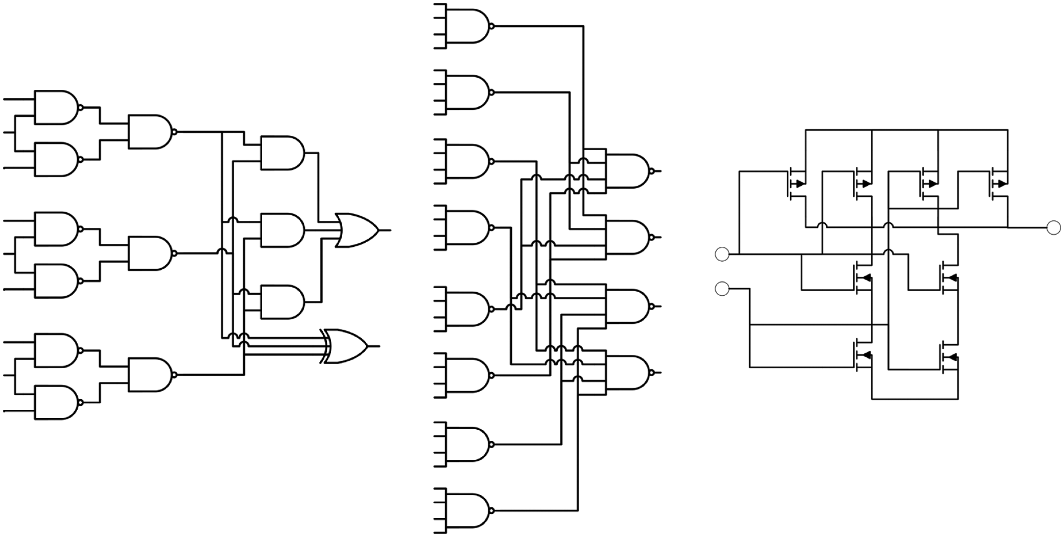
A variety of hardware strategies have been proposed that aim to bring increased resilience against SEE (and in some cases permanent faults) while attempting to minimising the resource overhead. Provision for MBU usually requires far more complex design than for SEU in order to meet the necessary fault capacity. On-chip memory is particularly vulnerable to MBU due to its dense structure, 8 but combinatorial logic cells are also at risk since faults induced by upsets may propagate to multiple registers. Of particular note are present-day field programmable gate array (FPGA) devices that contain large quantities of embedded static RAM (SRAM) where there is a growing interest in ‘design for reliability’ strategies that encompass functional diversity, modular redundancy, fine-grained fault-tolerant design and autonomous self-repair. 9 New design approaches are needed for custom logic, for which data error detection and correction (EDC) strategies such as two-dimensional hamming codes or fault-tolerant logic are typically applied. Figure 1 illustrates three examples of fine-grained logic redundancy strategies that have been proposed. Future nanoscale logic will require fine-grained design strategies to improve their manufacturing yield, 10 for which quadded logic 11 and temporal redundancy 12 architectures have been proposed.
The most prolific strategies for error tolerance in reconfigurable platforms are based on configuration scrubbing. This involves reloading a ‘golden’ configuration bitstream, either upon detection of an error or else performed periodically. 13 Periodic scrubbing is also combined with other fault-tolerant strategies, 14 but their use is energy-intensive and leads to unnecessary reconfigurations when no upsets have occurred. Explicit fault detection is challenging due to the transient nature of many types of SEU-induced errors, and in some cases, the error state may be present for some time before being detected. A number of existing self-repair strategies are capable of detecting and eliminating faults that accumulate sequentially over time, 15 but a major compromise is the need for explicit fault detection and repair logic that requires considerable resource overhead. These strategies also rely on effective discrimination between transient and permanent faults in order to avoid triggering unnecessary reconfigurations in the event of transient upsets (and thus potentially wasting valuable resources).
This article presents an alternative design strategy that is based on a self-recovering algorithm able to protect data patterns and logic configurations from SEU and MBU by continually refreshing the correct pattern at a fine-grained level. Redundancy is applied in the form of information stored within the elements of a cellular automaton (CA), which, in turn, creates a stable logic configuration that is highly resilient. This work is therefore distinct from previous work in that external error detection is not required: any deviations from the correct configuration pattern are immediately addressed by the internal cellular architecture and its regenerative behaviour. This strategy is further able to recover in the extreme case of an upset occurring simultaneously within every bit of the configuration pattern, provided permanent damage does not occur.
Design framework
In order to achieve resilience at the logic design level, a simple CA layer is utilised whose purpose is to protect the critical configuration of the functional logic. Functional logic is arranged as a functional component layer and is represented here by a regular array of configurable logic cells whose configuration is dictated by the CA pattern. This is analogous to the concept of configuring FPGA chips via data bitstreams. However, caution is needed when drawing this analogy because the architecture of current FPGA chips is not optimised for fine-grained online reconfiguration, and indeed, self-repair strategies that seek to achieve online configuration are highly complex and reply on sophisticated coordination. An example of this is the STAR algorithm, 16 in which a reconfiguration process continuously searches for and isolates faulty logic. Another example is the SABRE project 17 that utilises a custom application-specific integrated circuit (ASIC) design manufactured specifically for fine-grained reconfiguration. The architecture allows configurations to be implemented that are derived from complex evolutionary algorithms that seek to generate alternative configurations in the event of faults occurring within the hardware. The SABRE architecture uses parity EDC to protect against soft errors occurring within cells, with ‘gene’ code being reloaded when necessary. This is similar in principle to data scrubbing in FPGAs but at a fine-grained level. Reloading is done in two parts: hard errors are dealt with by the reconfiguration scheme where cells are shifted, while error codes are applied to the hard-fault tolerance architecture via parity distributed within processor cells. Thus, data EDC occurs independently within each ‘cell’ or control logic unit rather than being combined between neighbouring cells. Furthermore, the sMOVE processor may be regarded as a governing process that monitors the status of all cells. In this article, a decentralised approach is proposed for detecting errors within the configuration using a self-restoring cellular array that is continually driven towards a pre-defined pattern. If this pattern can be arranged to represent the configuration of the functional components (and can be re-generated should the pattern configuration become altered), then the logic configuration is repeatedly protected against transient upset events. In order to achieve the necessary regenerative property, rule sets are deterministically pre-computed by an algorithm rather than via evolution/mutation. The resulting convergent cellular automata (CCA) is considered to be a highly resilient pattern generator that protects the logic configuration by continuously enforcing its rule set. This design layer is referred to as the fault-tolerant coordination layer. CAs have also been proposed for protecting against node failures in multi-processor arrays including extension to two-dimensional topologies. 18 In this case, entire processing units are disabled in the event of a fault being detected and a reconfiguration of process scheduling occurs that is coordinated by the CA. A comparison of similar strategies was provided by Kamiura et al. 19 where, again, the subjects were processors and permanent faults were handled by reconfiguration.
Continuing the analogy with COTS FPGA technology, a CCA design can be regarded as a two-dimensional bitstream generator that is protected by the rule and state mapping solutions, which, in turn, maintains the FPGA’s configurable logic block (CLB) configuration. There are many ways in which to arrange the functional component layer that is coordinated (and protected) by the fault-tolerant coordination layer: here a two-dimensional grid geometry is chosen. Figure 2 illustrates the arrangement between functional and fault-tolerant layers, where a direct correspondence between each CCA cell and associated configurable functional block is established. The size of the required CCA is dependent on the granularity of the functional design, that is, how it is broken down at the logic design stage. A related concept has been proposed in the form of the plastic cell architecture 20 that also operates at fine-grained cellular logic design level. Indeed, this approach is similarly built upon a two-plane architecture using a coordinator layer (referred to as built-in logic) and configurable layer (referred to as plastic logic), although the actual governing mechanism is somewhat different to that proposed here.
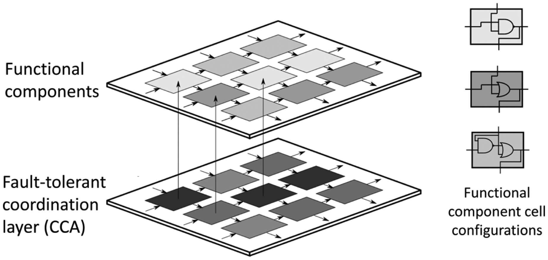
Illustration of resilient logic as a two-layer logic design incorporating a fault-tolerant coordination layer (comprising the CCA) and functional component layer above. Each functional component may adopt various configurations controlled by the state of the coordination layer. Three examples of functional logic component configurations are illustrated on the right.
Properties of the functional logic layer
The functional component layer forms an actual logic unit that becomes part of the active electronics. A design is shown in Figure 3 that implements a full-adder logic unit design that can be cascaded. 21 In order to configure the functional component layer, each cell is coordinated by the value of a CCA cell that directly asserts the correct logic function from a set of available configurations. Previous designs have focused on feed-forward circuits, whose interconnect structure ensures that data paths do not cross and feed in from left to right or top to bottom, ensuring that the data flow between logic blocks mimics that of the CCA itself. In the example shown, the associated CCA states are indicated in square brackets within each logic cell.
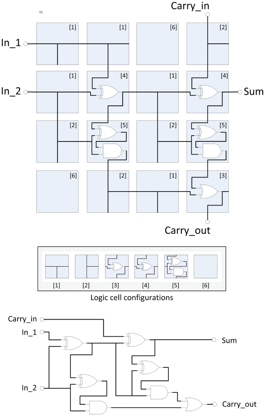
Example configuration of functional logic layer that forms a single-bit full-adder logic unit. Each cell has been configured from one of a set of available pre-defined logic configurations. CCA numerical states for this design are indicated in square brackets. For reference, the equivalent standard logic design is also shown.
Properties of the fault-tolerant coordination layer
The concept of self-configuring patterns arises from the CCA design and is composed of an array of cells, each capable of performing simple computational tasks. Interactions occur between neighbouring cells that are governed by a common rule set. The resulting behaviour displayed by the CCA is dependent on the rules used, boundary values and the allowable flow of nearest-neighbour signals. Fault detection is not explicit; individual cells continually update their state depending on the state of their immediate neighbours, effecting a continuous replenishment of the global pattern.
Considering a generalised two-dimensional CA, such as that illustrated in Figure 4, each cell obeys the same rule set stored in look-up table (LUT) form, which determines the next state of the cell in response to the values of neighbouring cells. In some limited cases, the rule set may create patterns that become static, that is, they no longer change after a certain number of time steps have elapsed. This particular situation can be exploited for robust design since the CA continually replenishes the static pattern even when one or more cells are disturbed. In previous work, 22 a set of conditions were proposed that achieve this behaviour for any target pattern and example rule sets were derived. An analysis of classical two-dimensional cellular automata showed that by restricting the flow of inter-cell communications to that of unidirectional signal flow and between neighbours from the north and west or from the south and east, a rule set may be derived that produces a stable steady-state pattern that is independent of the initial state of the CA. This restriction is illustrated in Figure 4 by the indicated directions of signal inputs and outputs. The resulting CCA is able to reassert the pattern in the event that it is forced to deviate from its intended state. Reconstruction occurs within a predictable number of discrete-time steps.
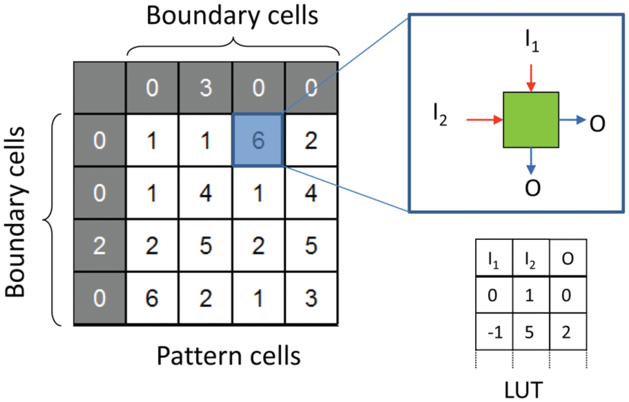
Structure of two-dimensional cellular automata, showing boundary cells, pattern cells, signal flow of intra-cell inputs (I1, I2) and outputs (O) and basic structure of rule look-up table.
CCA design strategy
In this section, a brief description of the design approach for generating CCA rule sets is described. For full details of the approach, the reader is referred to previous literature. 23 Referring once again to Figure 4, derivation of an efficient rule set for a given target pattern proceeds by direct inspection of the pattern and boundary cell values. It is also important that all derived rules must be unique. Referring again to Figure 4, each rule is composed of the tuple [I1, I2, O], noting that the present value of each cell is not included within the rule itself.
Mitigation strategy for rule conflicts
Each rule stored within the LUT must contain a unique mapping. A many-to-one rule conflict occurs when different next-state values arise from the same input values. For example, the rules (0,0,1) and (0,0,0) are non-unique. State conflicts are common, especially when the CCA pattern is encoded with a restricted number base. The above example rule conflict could be settled by incrementing the state value of one of the neighbouring state cells, for example, (0,2,1), (0,0,0), assuming the state ‘2’ is the next available unallocated state. The correct output value is retrieved by an additional state mapping LUT. Care is needed with this approach because state substitutions may generate further rule conflicts, and hence an iterative algorithm is needed.
A procedure for eliminating state conflicts is presented in Figure 5 using a state increment strategy based on a modified version of that described in Jones et al. 23 The algorithm is designed to detect the presence of boundary cells, which are assumed to be fixed, and hence, either north or west cell states may be incremented. In the rare case of a rule conflict being attributed to the top-left cell (where neither west nor north cell can be altered), the cell attributed to the second rule conflict is instead incremented.
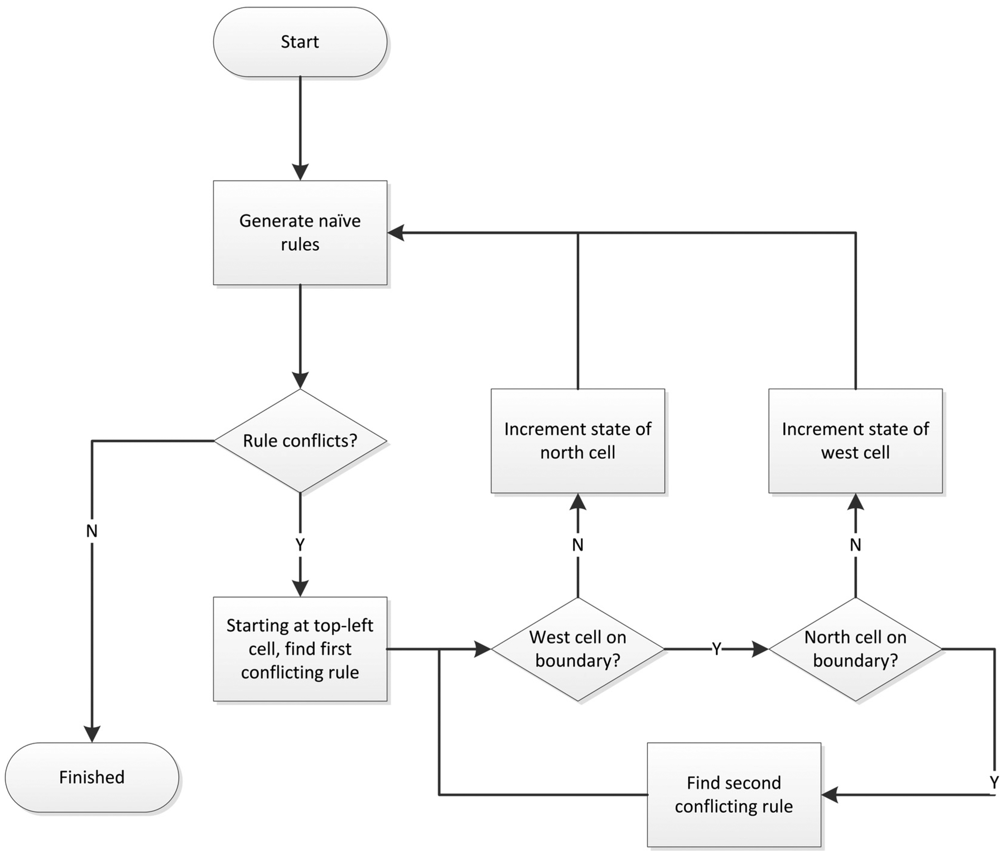
Flow diagram of algorithm used to resolve rule conflicts.
LUT resource requirements
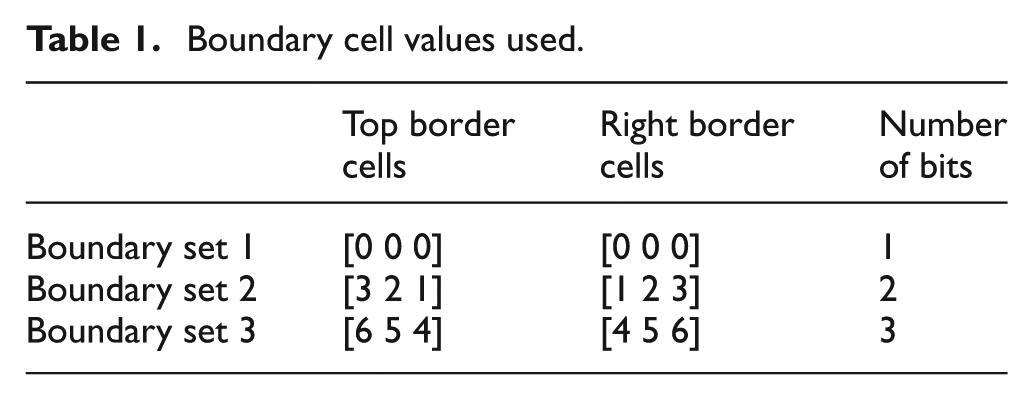
In order to quantify the LUT resource overhead, a detailed study of the rule size for a large number of different binary target patterns was carried out. Beginning with 3 × 3 CCA patterns, every possible combination was examined (i.e. 29 patterns) and a minimal rule set generated according to the method is described in section ‘CCA design strategy’. To better understand the influence of the boundary cell values on the resource overhead, the design requirements for each CCA pattern were assessed using three sample boundary sets as detailed in Table 1. Boundary set 1 is a simple zero boundary pattern requiring the simplest logic in order to assert logic ‘0’ at boundary cells. Boundary set 2 increases the information contained in the boundary set to base 4, requiring two bit lines to encode the values {0,1,2,3}. Boundary set 3 further increases the information to base 6, requiring three bit lines. This final set is arranged such that the values in the boundary cells become decoupled from CCA cell values with the aim of decreasing the number of rule conflicts and additional states required to solve the CCA rule set.
Boundary cell values used.
Analysis of 3 × 3 patterns
The number of additional states introduced in order to resolve rule conflicts is an important measure of the necessary design complexity. A large number of additional states will require more bit lines to encode state information between neighbouring cells, leading to higher interconnect density. For each of the boundary sets, every 3 × 3 CCA pattern was solved, rule conflicts were resolved and the necessary number of states was aggregated. Figure 6 shows the resulting histogram distribution for each boundary set. For boundary sets 1 and 2, certain patterns require three intra-cell bit lines to handle up to eight states. In contrast, the values used in boundary set 3 are sufficiently decoupled from the pattern state values that the number of states is contained between the range (1,…, 4), enabling the use of two intra-cell bit lines.
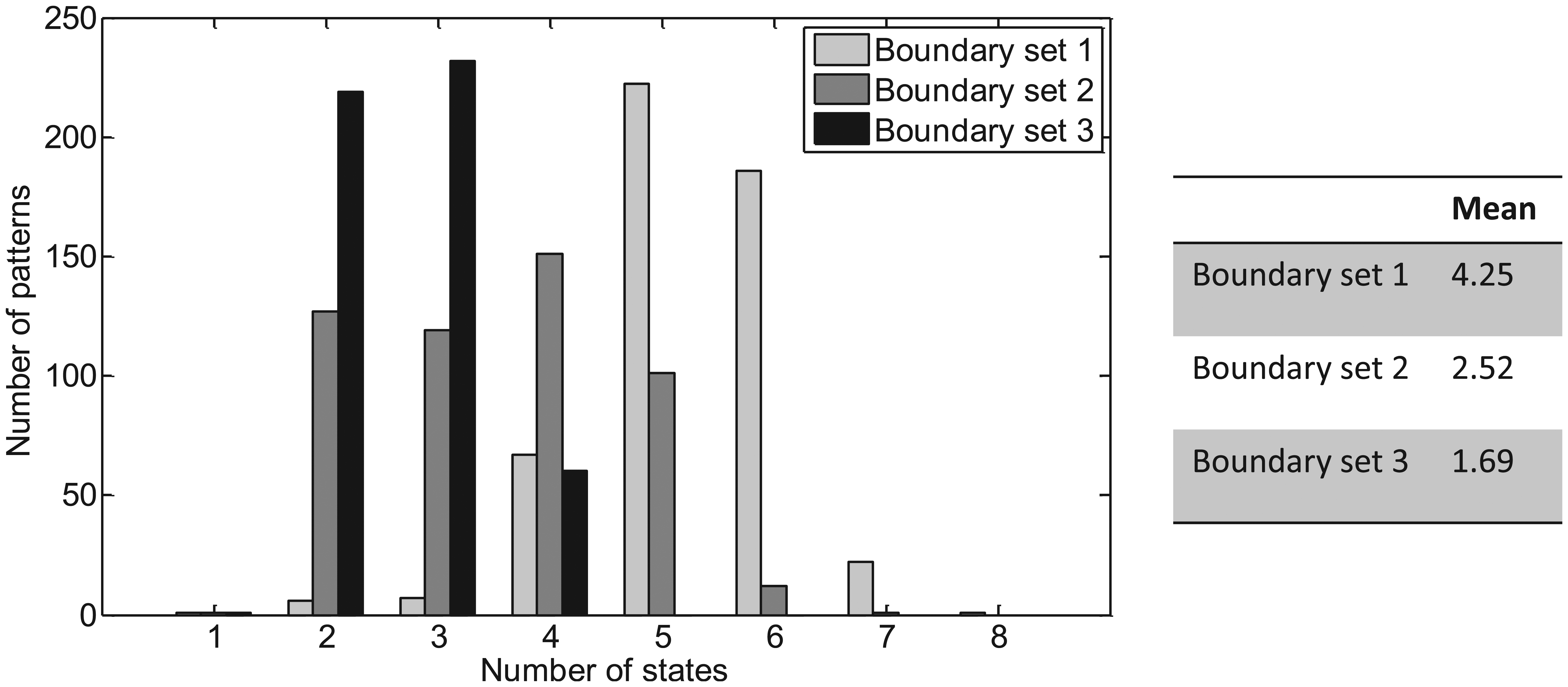
Number of CCA states for 3 × 3 target patterns. Left: histogram distributions of number of states required for CCA encoding for 3 × 3 binary patterns (including rule conflict resolution) and using different boundary cell values. Right: mean number of states needed to encode 3 × 3 patterns for each boundary set.
The number of rule conflicts encountered for each target pattern is summarised in Figure 7, which provides a measure of the effectiveness of each boundary cell set. Both boundary sets 2 and 3 result in two or more conflicts for some patterns; however, conflicts are resolved more efficiently for boundary set 3.
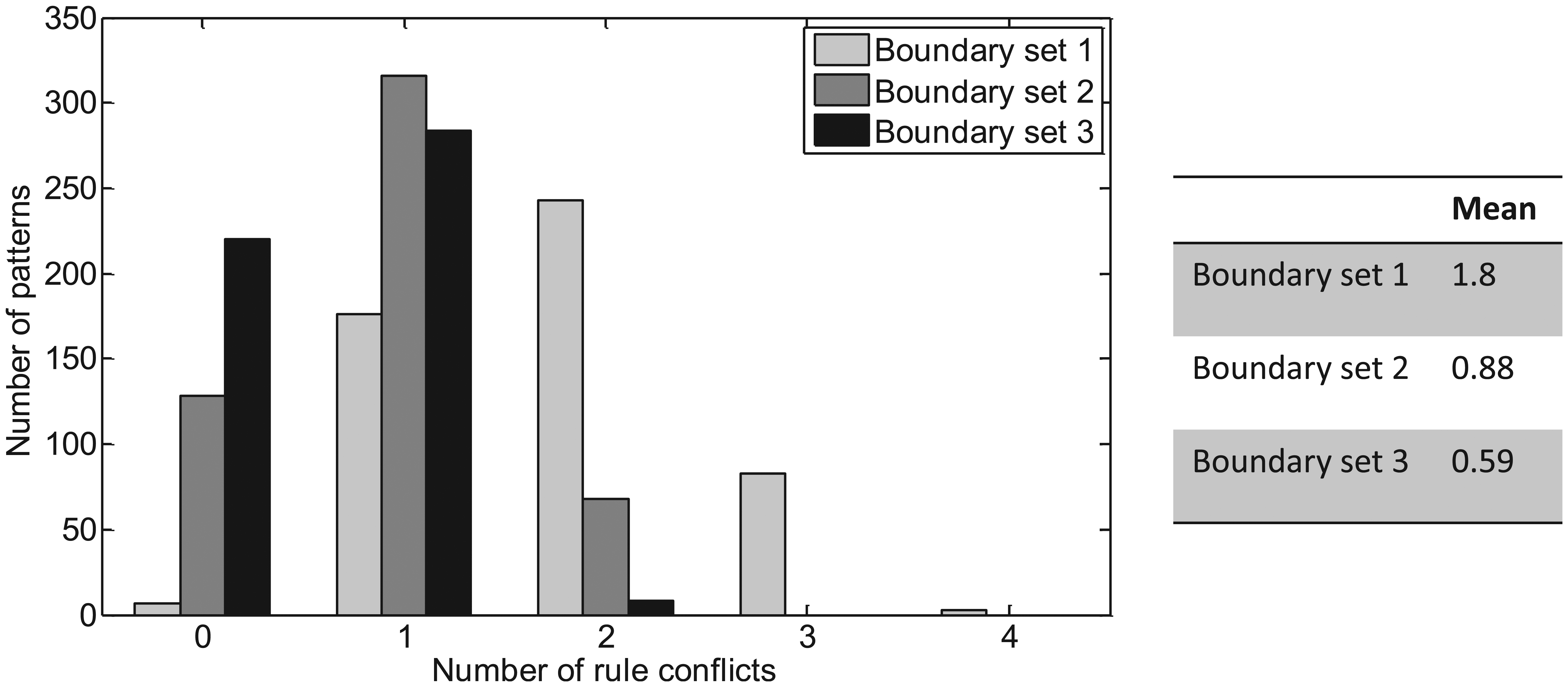
Number of conflicts resulting from each pattern.
Figure 8 shows the number of rules required for each pattern, which dictates the size of the LUT in each cell. In contrast to the number of states, the choice of boundary set does not greatly influence the number of rules required to resolve conflicts suggesting that the rule set is not easily compressible.
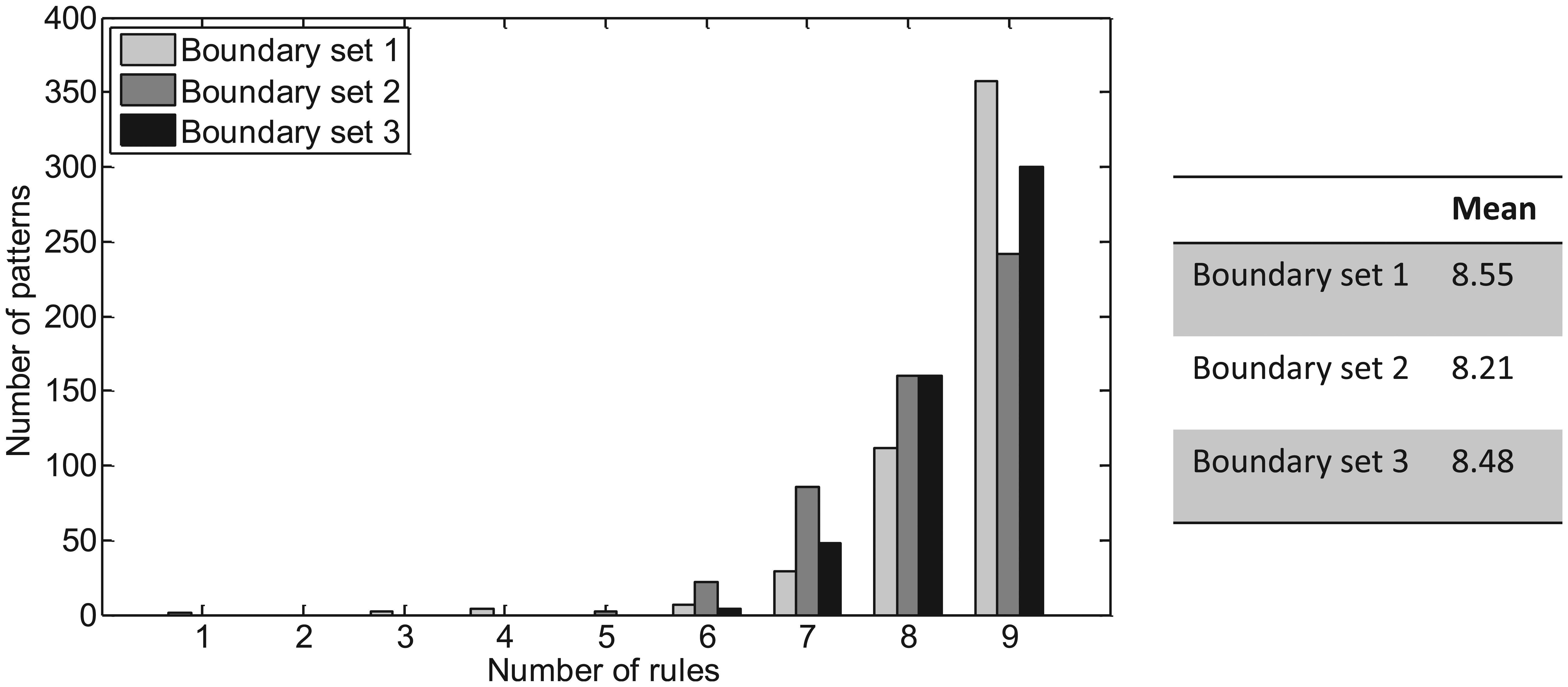
Number of rules required to resolve rule conflicts.
Figure 9 illustrates the variation in state mappings for each boundary set, which determines the size of the state map LUT. In contrast to the rule set, the number of state mappings is highly dependent on the pattern and boundary conditions. It is seen that the size of this LUT varies between zero and six entries and for boundary set 3 does not exceed two entries.
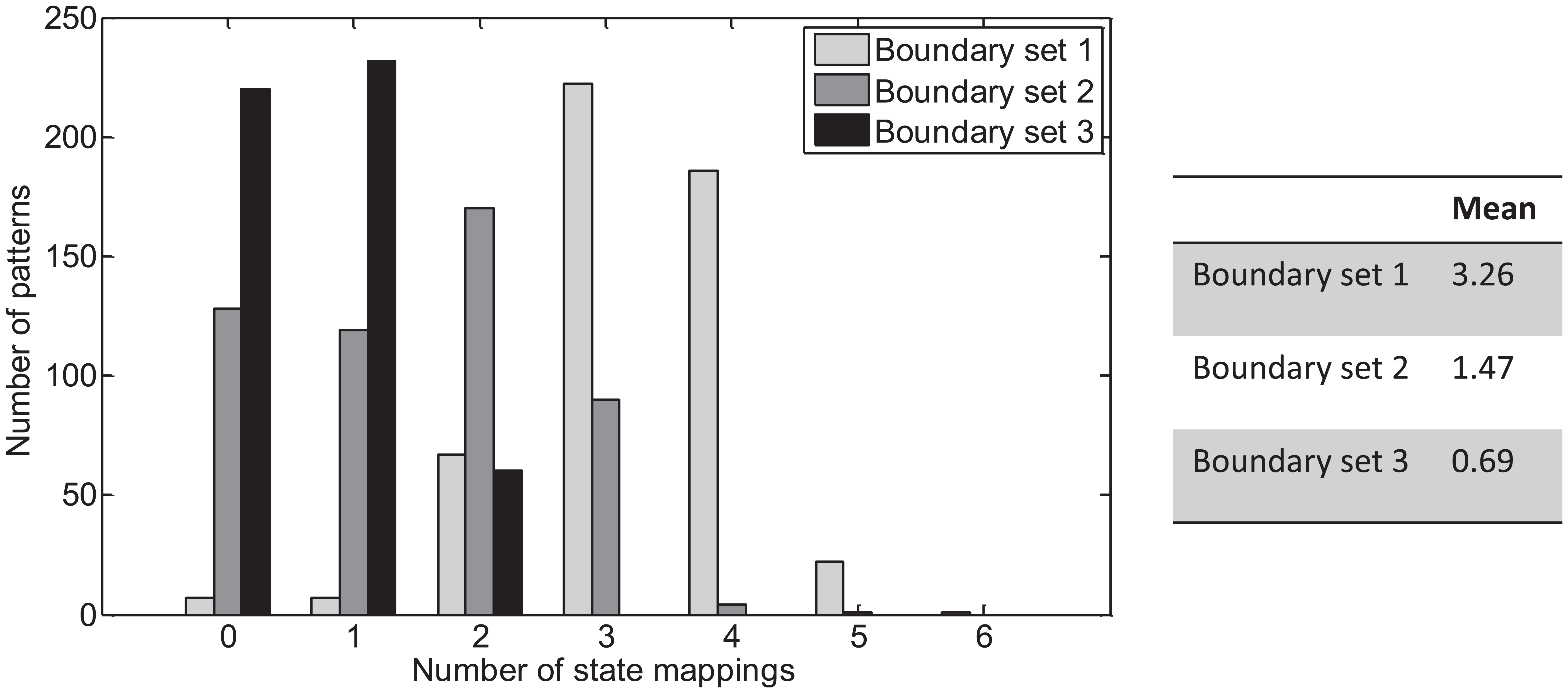
Number of state mappings required to resolve rule conflicts.
Analysis of 4 × 4 patterns
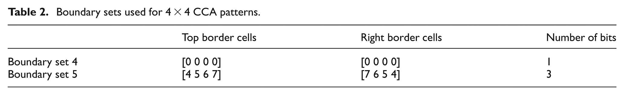
To further investigate how the above parameters scale with CCA pattern size, the procedure described above was repeated for all 4 × 4 patterns (i.e. 216 combinations). For this case, two boundary sets were used as detailed in Table 2. The resulting mean number of rules, states and state mappings are summarised in Table 3 along with their standard deviation. Significant reductions result from using the more complex boundary set 5 with similar standard deviation. Histogram data are again presented for this boundary set (Figure 10), where once more it is seen that the number of rules is biased towards the right-hand side of the distribution. For this larger sample set, both the number of rules and state mappings appear to acquire a Gaussian-shaped profile. It can also been seen from the graphical results that at least three bit lines are needed for intra-cell communications and in many cases four bit lines are required – less than that required for the boundary cell values. A trade-off does, however, exist in terms of the size of the rule/state mapping LUTs: referring again to Figure 10, it is evident that for some patterns there are no additional state mappings required. However, these particular patterns require the highest number of rules and therefore a largest LUTs.
Boundary sets used for 4 × 4 CCA patterns.
Statistical results for 4 × 4 patterns.
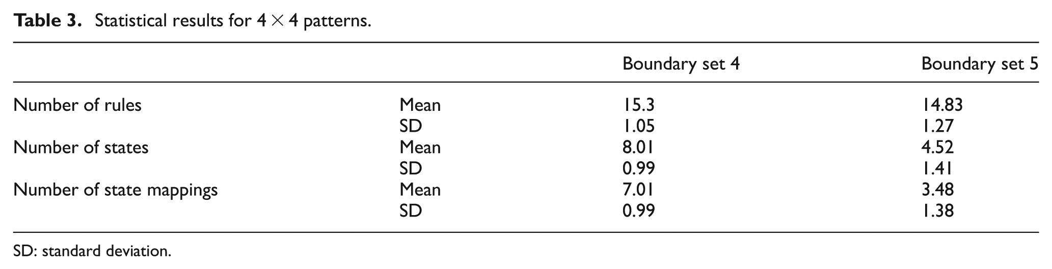
SD: standard deviation.
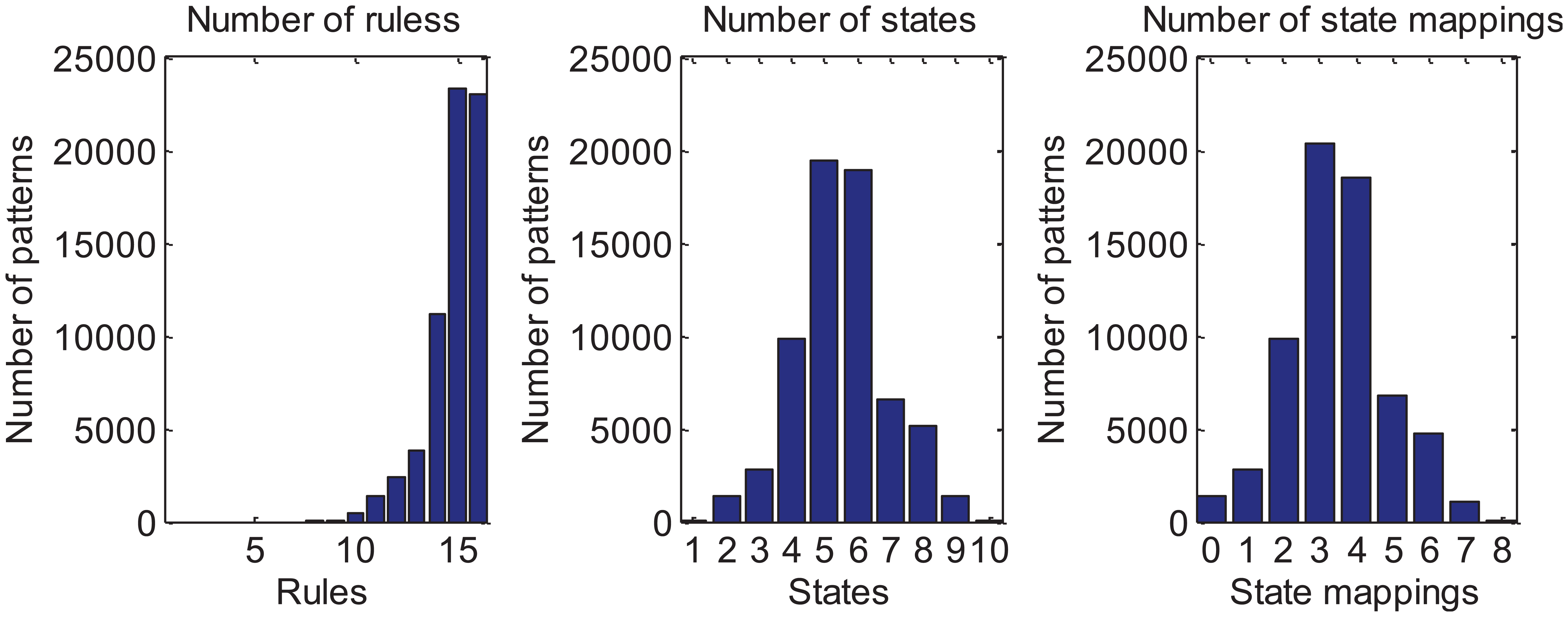
Distributions of results calculated for 4 × 4 patterns and boundary set 5.
Conditions for self-configuration and recovery
Self-recovery requires that rule set is correct (and can be relied upon) and that the boundary values are correct. An example of the self-restoring property is illustrated in Figure 11, where the initially correct pattern is disturbed and rebuilds by reasserting the correct cell state.
Example of self-restoring of pattern following multiple upset. Cells affected by upsets are shown shaded. This particular pattern requires 15 rules.
Clearly, the LUT contents within each cell must be valid in order for the correct pattern to emerge. In the event of SEU/MBU occurring within an LUT, the error condition may clear by itself, in which case the correct pattern will re-emerge. If the error does not clear, then reassertion of the correct LUT contents becomes necessary. Strategies based on either mutual self-checking between neighbouring cells or else the use of global LUTs with redundancy would likely form effective protection. In the former case, each cell periodically checks the contents of its own rule and state LUTs for consistency with those of its nearest neighbours, thus retaining the cellular design concept. In the latter case, the rule and state LUTs are instead stored centrally and protected by standard triple modular redundancy (TMR) or similar approach. Central LUT storage requires fewer LUT memory cells but significantly higher interconnect density between cells. A key design consideration here is the effective radiation cross section presented by either localised or global rule storage and is the subject of future work. One possible CCA design for this pattern is shown in Figure 12 where the boundary cell values have been chosen such that 15 rules are required with no rule conflicts. Note that this design requires three bit lines between each cell in order to encode the states [0 … 6].
CCA pattern for full-adder logic design requiring 15 rules.
Example design
For the purposes of demonstration, the full-adder logic design example detailed in Figure 3 may be implemented in hardware description language (HDL) and used to create the architecture shown in Figure 13. In this example, each design cell contains both the fault-tolerant coordination and respective functional component logic cell along with the necessary LUTs. Hence, each cell contains the superimposed equivalent of the two-layer design illustrated in Figure 2. While COTS FPGAs are not optimised for efficient implementations of such designs, they serve as a useful platform for functional verification and hardware fault emulation. In this example, a Xilinx Vertex 5 was used and a VHSIC Hardware Description Language (VHDL) description of each cell containing rule and state mapping LUTs was synthesised/mapped to a configuration bitstream. A hardware-in-loop interface can then be used to verify the logic configuration and functionality under SEU/MBU fault conditions. An example of a fault test is illustrated in Figure 14, in which an injected fault produces error states that are removed by the regenerative action of the CCA.
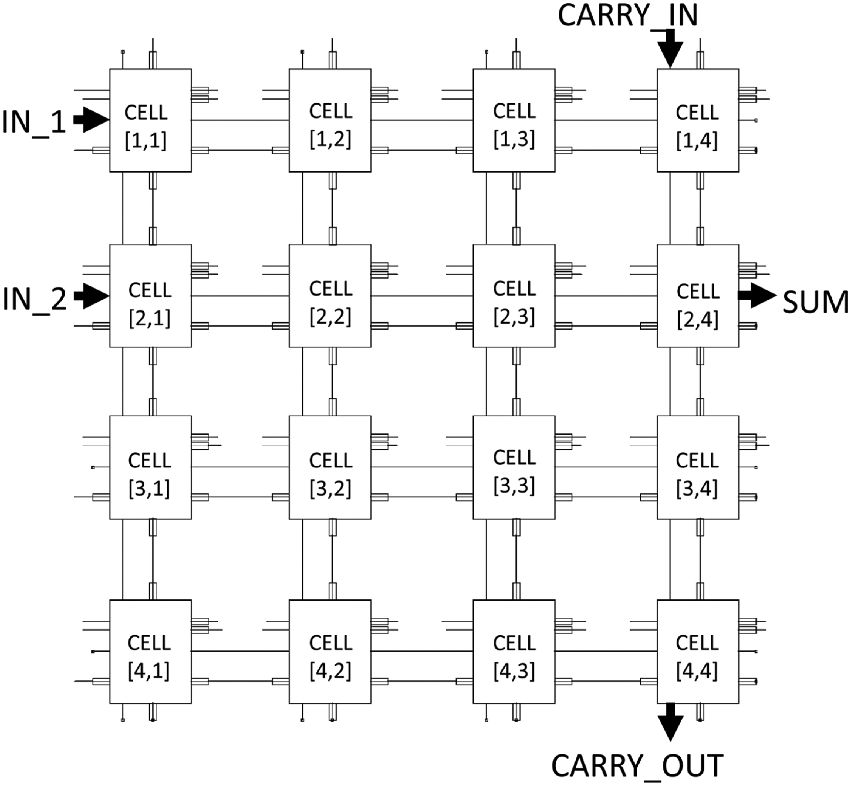
Schematic cellular design concept. This example shows a 4 × 4 cell array in which each cell contains both a CCA and respective functional logic cell.
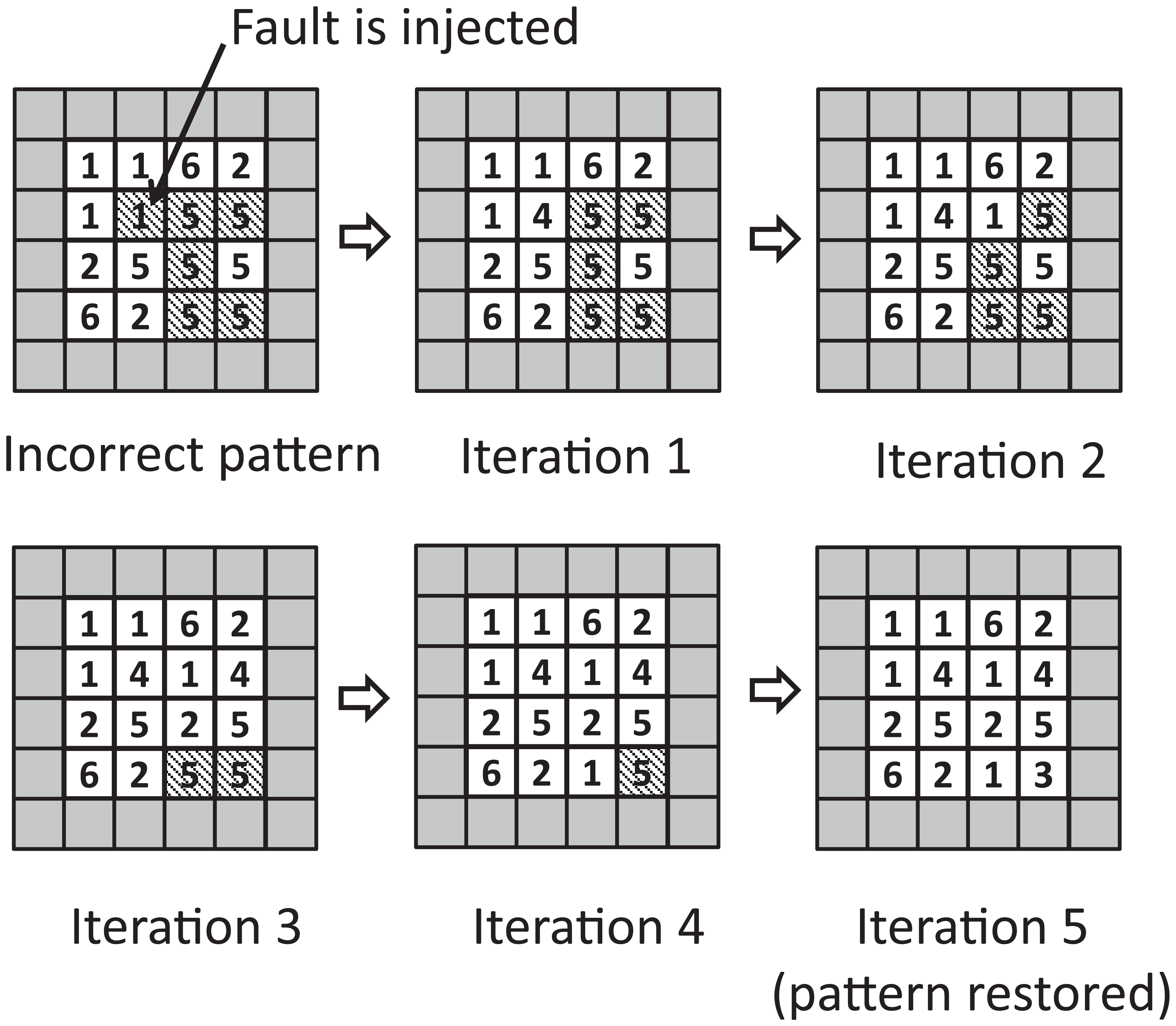
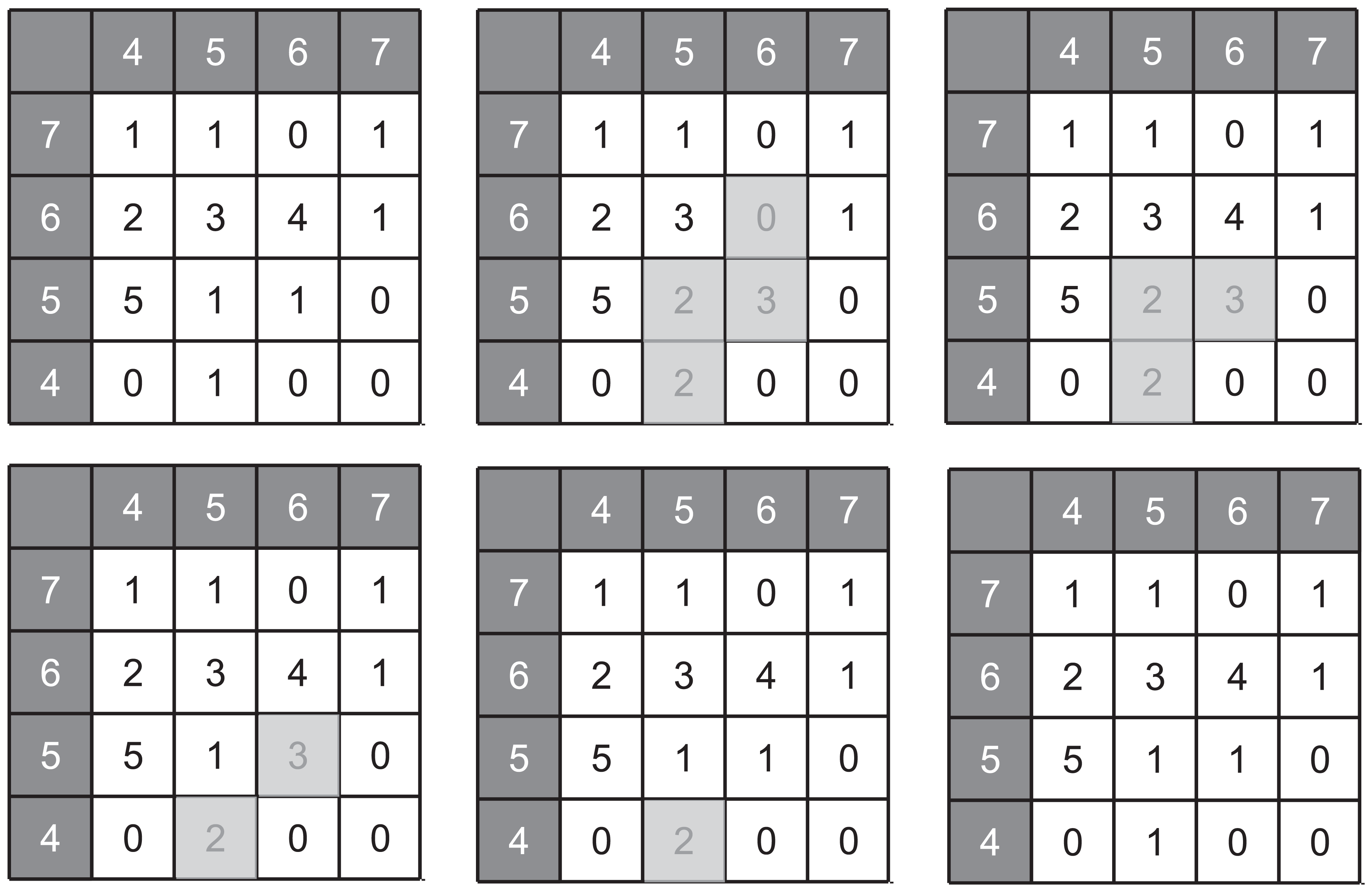
Example of recovery from fault injection in a 4 × 4 CCA. Incorrect internal state is injected into a single cell as indicated, followed by pattern restoration after five successive iterations of the rule set. Boundary cells (=0) are shaded and incorrect output cells are hatched.
Fault detection
An interesting prospect of this implementation is that fault monitoring is possible within certain design combinations by monitoring the behaviour of output boundary cells disposed along the bottom-most row and right-most column of the CCA. These are referred as output cells. When an incorrect state occurs, fault information is propagated to the output cells via deviations from their intended states. This property may be exploited to produce signals that indicate the occurrences of SEUs within the main body of the CCA and that may be exploited as an additional feature beyond self-restoration. Note that the absolute state of the output boundary cells need not be known a priori – only the knowledge that their state has been altered is required. This is may be useful in situations where self-recovery is not by itself sufficient, and where a logging of upset events is useful for long-term monitoring.
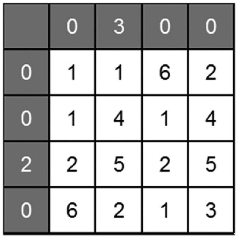
An example of a fault-sensitive design is illustrated in Figure 15 for a 4 × 4 target pattern. In this design, the input boundary cells are all set to the value 0, thus forcing the creation of additional states within the pattern matrix during rule generation. The design requires 15 rules and 7 state mappings. Although the rule and state mapping resource requirement could be reduced by increasing the complexity of the input boundary cell values, this would reduce sensitivity to faults. The introduction of additional rules and state values increases the likelihood that a fault will change one or more output cell. In this example, a fault is assumed to create the stuck-at value of ‘2’ and the CCA exhibits a change in its output cells as a result. A sensitivity analysis was conducted by changing the location of the stuck-at fault and checking for a change in the output boundary cells. The results, summarised in Table 4, show that with one exception, at least one output cell event manifests for every fault location. An exception is when the fault is located at cell (4,2) where stuck-at value is equal to the correct cell value.
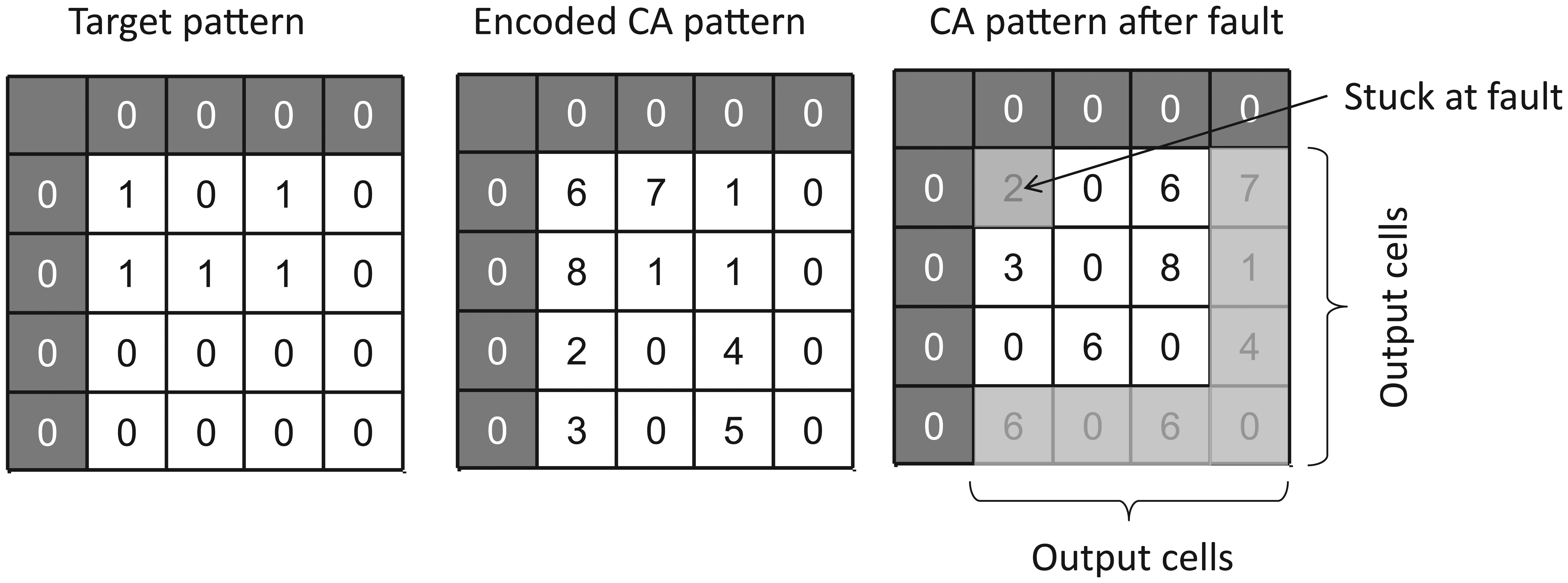
Example of stuck-at fault occurring at cell (2,2) and the resulting alteration of output boundary cell values. Stuck-at fault creates the cell value ‘2’.
Fault analysis for stuck-at fault value of ‘2’.
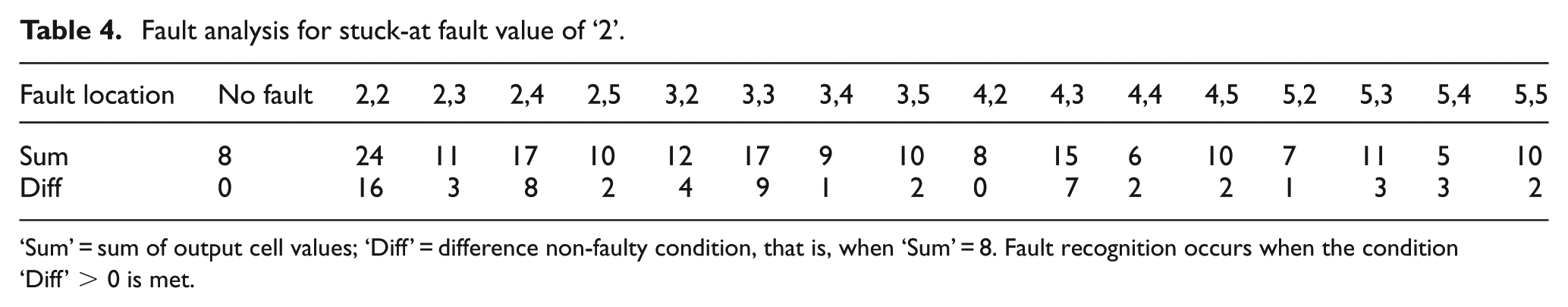
‘Sum’ = sum of output cell values; ‘Diff’ = difference non-faulty condition, that is, when ‘Sum’ = 8. Fault recognition occurs when the condition ‘Diff’ > 0 is met.
The above result is somewhat restricted to specific design cases because sensitivity is not guaranteed for all the stuck-at values nor for all CCA patterns. However, the likelihood of fault detection is increased by implementing a larger state LUT (at the cost of higher resource overhead).
Design and manufacturing considerations
Referring again to Figure 3, the number of state LUT entries determines the number of logic cell configurations and hence the resource overhead of the functional component layer. The size of the respective rule LUT is determined by the efficiency of the rule and state mapping algorithm. Hence, efficient coding of the CCA rule/state LUTs is critical to minimise logic overhead since each LUT is stored within every cell.
It is worth pointing out that the central goal of our approach is that, provided the CCA rule LUTs are preserved, the design is made highly resilient to transient faults occurring within the CCA cell states (i.e. the state of the coordination layer) and therefore within the functional component configuration. However, the hardware memory LUT and sequential logic associated with each cell of the CCA may also be sensitive to SEU and/or MBU. For the purposes of this study, it has been assumed that the CCA rule LUTs are fixed and do not contain errors and, for example, may be implemented as ROM tables that are relatively insensitive to SEE. Programmable designs do, however, require RAM blocks, in which case it is clear that further protection by EDC would be advisable to protect against corruption of the LUTs. Since each CCA cell uses identical rule and state LUTs, an efficient design variation would involve clustering of LUTs shared among multiple cells each protected by EDC as discussed in section ‘Conditions for self-configuration and recovery’.
Design flexibility may be traded for reduced resource overhead in some cases by relaxing restrictions on signal flow direction, thus permitting the use of combined logic blocks that include overlapping signal routing. This would afford a greater compression of the design through abstraction between coordination and logic layers at the expense of more complex intra-cell routing. A similar effect is observed in current FPGA chips, where interconnect accounts for a high proportion of chip area and power consumption. An example of this approach is illustrated in Figure 16, in which a full-adder design is arranged as two cascaded half adders, an OR block and a routing block. Clearly, this approach delegates more complex logic cell configurations than the example shown in Figure 3 and therefore has reduced the scope for both design reuse and fault detection. However, both interconnect density and CCA size are greatly reduced.
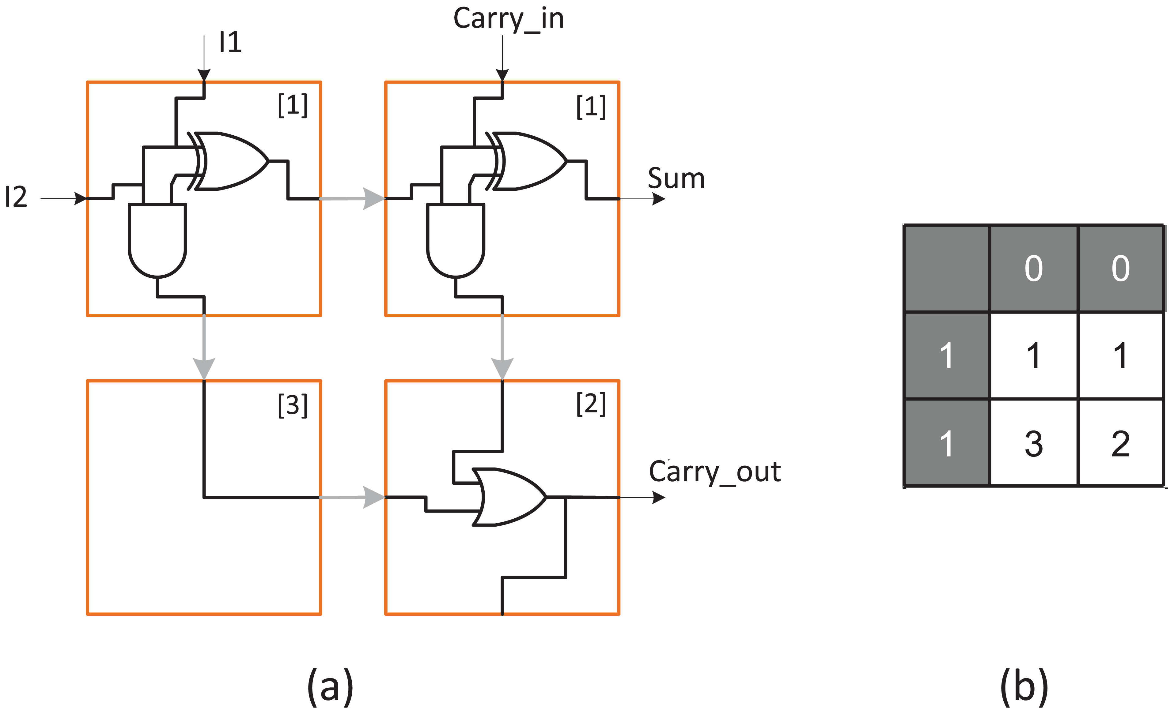
Simplified adder design using (a) half-adder blocks and (b) requiring three rules.
Summary and conclusion
A self-configuring strategy was presented that increases the resilience of electronic systems against SEU and MBU. The approach taken protects functional logic configurations and is thus considered to be complementary to the existing hardware design techniques already employed for cost reduction of through-life maintenance of complex systems. From the exhaustive target pattern investigation presented in section ‘LUT resource requirements’, the number of required CCA states, rules and state mappings is strongly dependent on the chosen boundary conditions. This study is restricted to binary target patterns since all digital logic implementations are ultimately implemented as binary-encoded designs. Although reductions in the size of the rule and state LUTs are possible by judicious choice of boundary cell values, there are limitations: first, the rule set is not readily compressible since it reflects the complexity of the pattern and its encoding in the form of rules. Second, a reduction in the number of cell states does not immediately result in fewer intra-cell interconnects. This is due to the fact that those pattern cells abutting boundary cells must be able to address at least one boundary value in their LUT, requiring additional data lines. Further work is needed to determine the most effective method for self-checking of rule and state LUTs, either at the cellular level or else using clustered LUTs. The hardware test bench test system described in section ‘Example design’ confirms that functional operation of the approach, but further evaluation requires custom logic design.
The strategy is well-suited to the protection of data patterns stored in memory for finite state machine logic and configuration bitstreams for configurable logic. The distributions observed in the 4 × 4 pattern analysis showed Gaussian-type properties for the numbers of states and state mappings, and a biased trend for the number of rules, which may be useful for predicting the resource requirements for larger data patterns that cannot be studied by the same exhaustive procedure. It should be noted that a further trade-off exists between LUT size and fault detection capability. Furthermore, for some applications, a more favourable compromise may be found using standard EDC deployed in regions that are vulnerable to SEU. However, the self-restoring strategy presented here is beneficial for cases where application is sensitive to MBU, where fault detection/localisation is advantageous and when self-initiated restoration is compatible with the application.
The handling of permanent errors (e.g. transistor burnout or latch up) caused by degradation or extreme environmental conditions is beyond the scope of this article. However, assuming that a faulty cell may be uniquely identified, possible mitigation strategies include diverting inter-cell input/output (I/O) lines to a spare cell (incurring a high interconnect resource overhead) or implementing entire rows or columns of spare cells used to replace any row or column containing faulty cells. These techniques pose a major challenge because dynamic CA rules are then needed in order to alter the CA reconfiguration. Genetic algorithms are capable of adapting to permanent faults occurring in configurable logic but require global computing resources and may exhibit unbounded repair time. In contrast, CCA rule sets are computed deterministically and their recovery time is bounded. The through-life care of future engineering systems will depend on a combination of both permanent and transient fault mitigation strategies.
Footnotes
Declaration of conflicting interests
The author(s) declared no potential conflicts of interest with respect to the research, authorship and/or publication of this article.
Funding
The author(s) disclosed receipt of the following financial support for the research, authorship, and/or publication of this article: This work was supported by the EPSRC Centre for Innovative Manufacturing in Through-life Engineering Services (EP/I033246/1).