
Abstract
An ultra-precision ball rotating displacement measurement setup based on laser focus deviation was presented. The setup is capable of measuring ultra-precision ball rotating displacement at nanometer sensitivity. The experiment results indicated that the method has high repeatability and potentially with high throughput. A dual-probe setup is also studied to evaluate diameter variation in a ball with errors introduced by misalignment, while spindle radial vibration being automatically eliminated. Optical probe-based ultra-precision ball displacement and diameter variation measurement are suitable for in situ application with high throughput and repeatability.
Keywords
Introduction
Ultra-precision bearings are key elements in modern industries1,2 as they are widely used in almost all motion systems. Parameters such as out of roundness, diameter variation, and surface roughness are key measuring criteria that determine the grade of a ball or a roller, hence directly affect the performance of a bearing. As modern ultra-precision fabrication and processing approaches sub-micron and even tens of nanometer scales,3–5 measurement capabilities must match the advancement in fabrication 6 to ensure quality. However, for high-grade ball and roller manufacturing, applicable measurement methods in production lines still largely rely on traditional stylus methods. 7 Due to the contact nature of stylus probes, measurement throughput is greatly limited. It is therefore necessary to explore high throughput, high accuracy, and high repeatability measurement method to meet the demand for ultra-precision ball and roller manufacturing. Although traditional optical measurement methods such as laser interferometer 8 for form measurement, heterodyne laser interferometer 9 for displacement measurement, and scanning white light interferometer 10 and other optical profilometry 11 for three-dimensional (3D) measurement are more advantages in accuracy and/or measurement speed compared to stylus methods, they are not suitable for roundness or rotating displacement measurement of balls and rollers due to various reasons, such as limited field of view, requirement for a flat surface and limited lateral resolutions (for heterodyne laser interferometer), and low measurement speed. Single-point non-contact optical probe for roundness and rotating displacement measurements were reported by several research groups, and excellent results were reported;12–14 however, no commercially available non-contact roundness and rotating displacement measuring devices with nanometer sensitivity had been introduced to market. A new displacement measurement method with home-developed optical sensors is introduced here, which is potentially suited for production applications. The method shows advantages in high repeatability (better than 10 nm with 1σ), high throughput, and relatively large dynamic range.
Measurement principle, error analysis, and experiment results
Measurement principle
Laser focus deviation displacement measurement utilizes a position sensor and a focusing optics to measure surface displacement caused by focus shift. The laser beam is spatially filtered to achieve high point stability. Figure 1 shows a simple optical layout of the device.
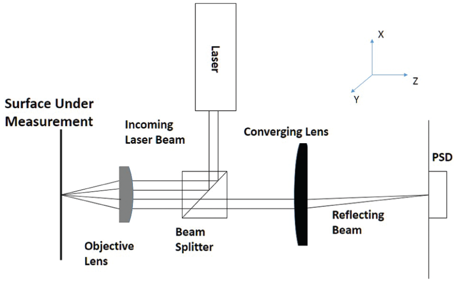
Optical layout of the laser focus deviation displacement measurement.
When the surface under measurement is at the focal plane of the objective lens, the image of the focusing spot at the surface will be at the center of a position sensing detector (PSD). When the surface moves away from the focusing plane, the image spot will shift laterally on the PSD as shown in Figure 2.
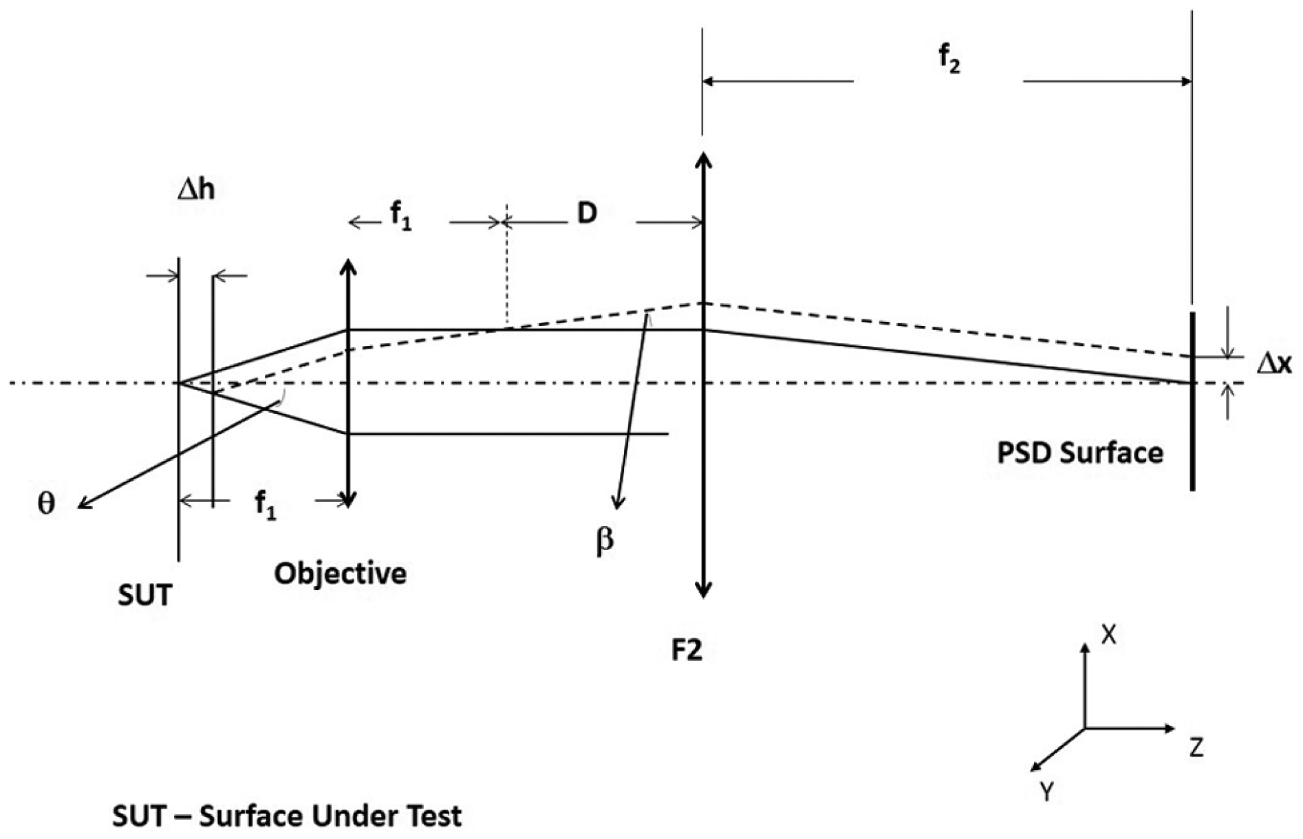
Relationship between vertical displacement Δh versus horizontal shift Δx.
Here, Δh is the displacement of the surface from the focusing plane. f1 is the focal length of the objective lens, D = f2 is the focal length of the imaging lens F2, and Δx is the lateral shift of the image spot on the PSD. It can be shown that the lateral shift (along the x-direction) on the image plane and the vertical displacement (in the z-direction) of the measuring surface are related through the following equation
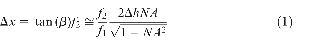
Here, NA is the effective numerical aperture of the objective lens, which is always less than the numerical aperture of the objective lens. The amount of shift is recorded and converted into electrical signal and can be further processed.
Measurement error analysis
Equation (1) is correct as far as the normal of the measuring surface is parallel to the optical axis of the objective lens. If the surface under measurement has a nonzero tilt of
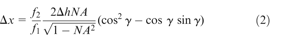
Here,
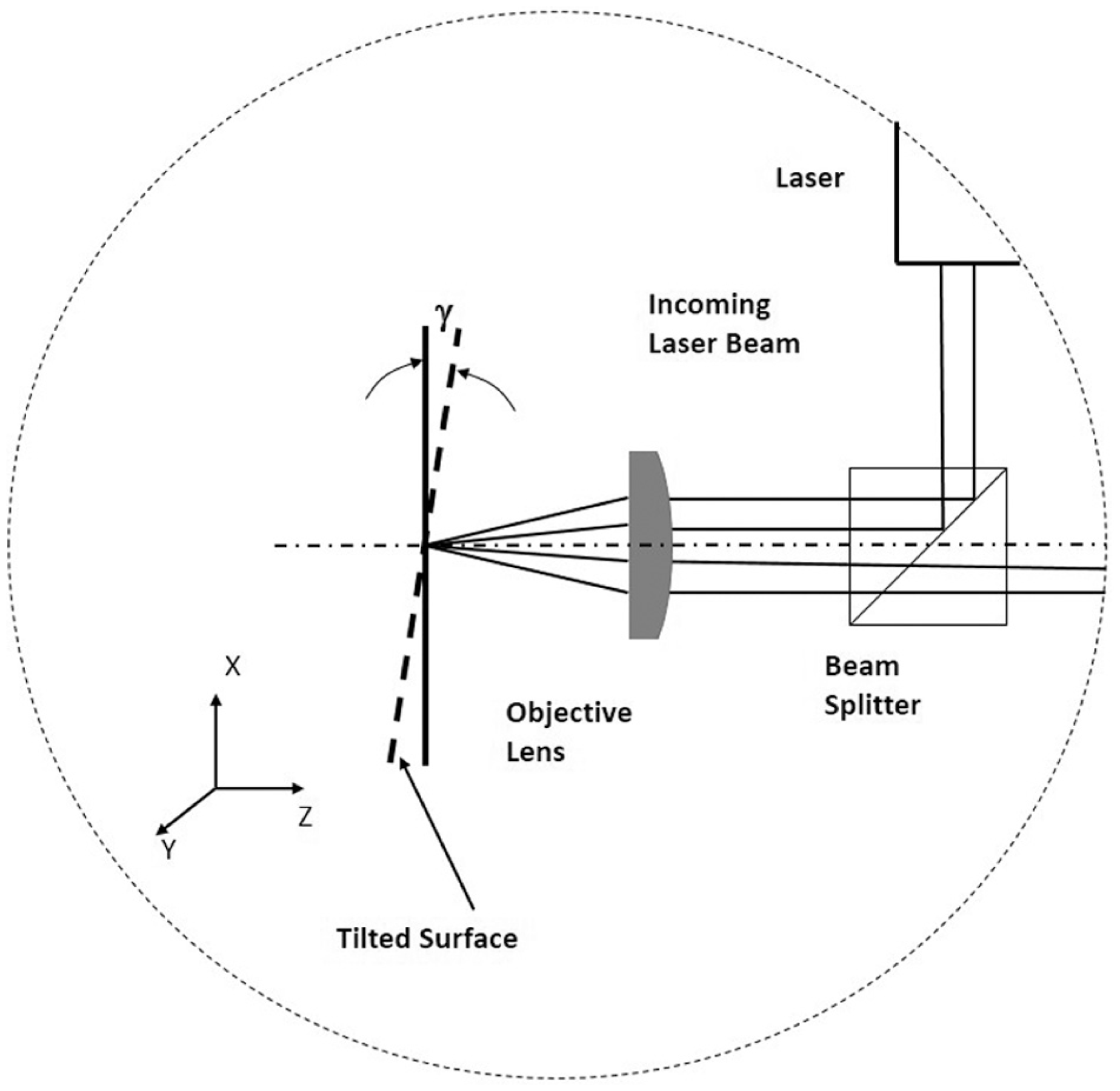
Surface under measurement has a tilt angle of γ.
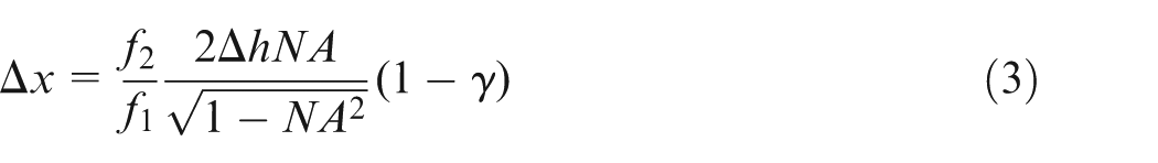
For small tilt, equation (2) can be approximated as equation (3)
To minimize any influence of laser intensity fluctuation on the measurement, a differential normalization method was applied to the measured signals
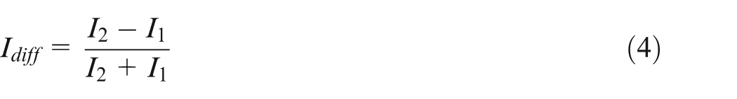
Here, Idiff directly relates to the surface displacement.
Ball rotating displacement measurement alignment error
To measure rotating displacement, hence the out of roundness of a ball, the ball needs to be placed on a spindle chuck and aligned with the center of the ball with the rotational axis of the spindle. The optical measurement probe is placed horizontally with its optical axis in the same plane of the ball’s equatorial plane and is perpendicular to the spindle axis as shown in Figure 4.
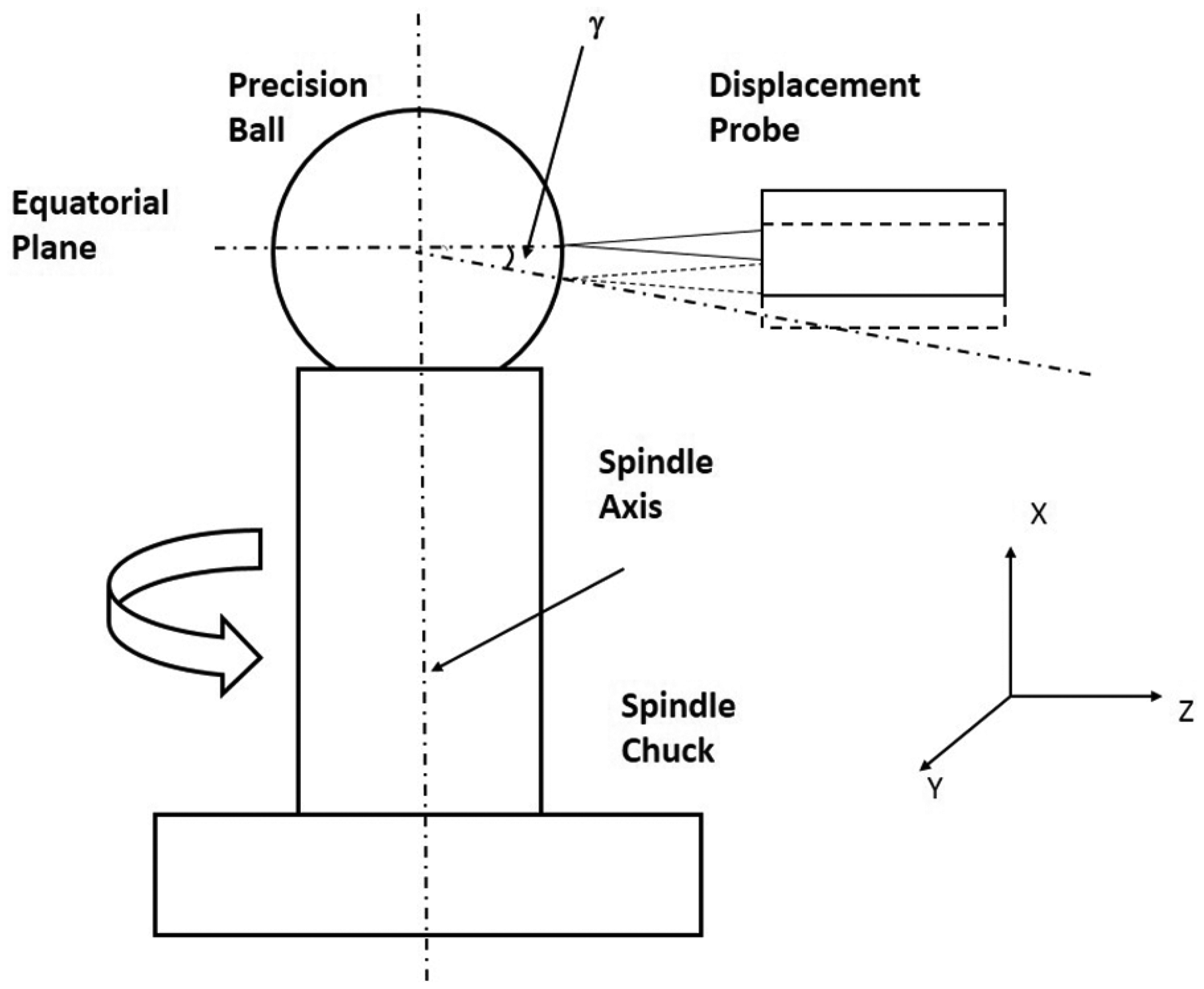
Single-probe arrangement.
In this measurement configuration, there are three error sources affecting the ball displacement measurement. One is the probe optical axis misalignment with the equatorial plane of the ball. A small up/down shift of the optical axis of the probe (shown as dashed probe in Figure 4) relative to the equatorial plane will cause the ball surface normal and the probe optical axis to have a small angle γ (as shown in Figure 4), which will result in measurement error as estimated by equation (3). With the ball diameter at 50 mm, a 10-µm shift corresponds to less than 0.05% of displacement measurement error. The second error is due to the residual center misalignment r between the ball center and the spindle chuck rotational axis (see Figure 5); the third error is the spindle radial vibration during rotation.
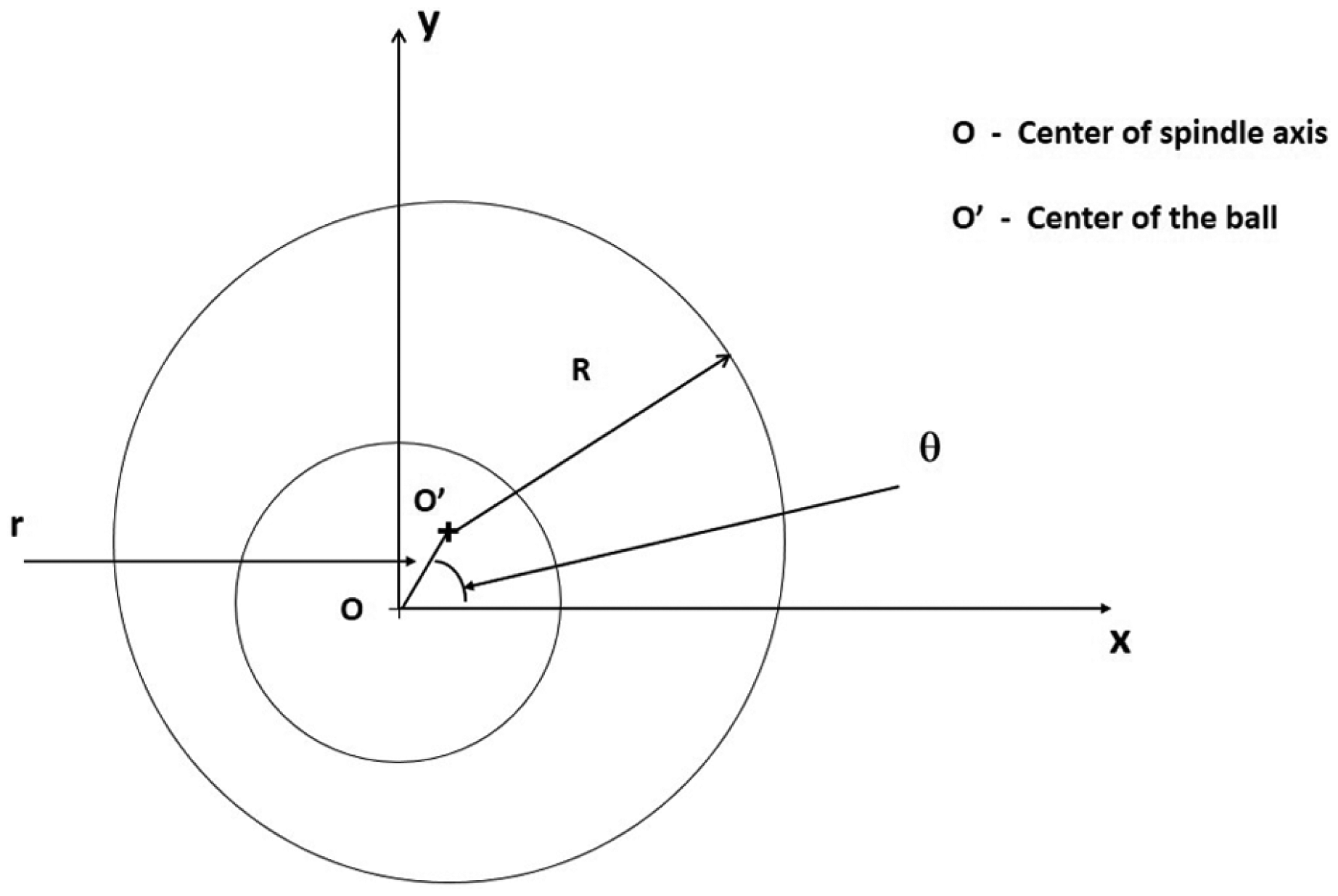
Spindle center and ball center misalignment by r.
Alignment error r causes a measurement error that can be expressed as follows
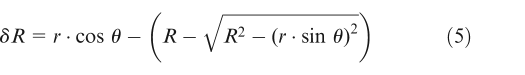
Here,
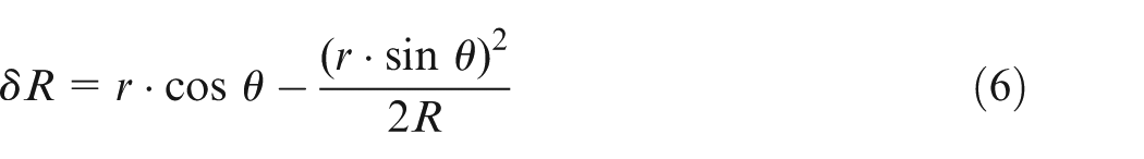
The first term in equation (6) represents the displacement error caused directly by center misalignment. The second term represents error due to the shifting of the ball in x-direction during rotation, which is much smaller compared to the first term. Take R = 25 mm for example, the largest error of the second term will occur when
The spindle radial vibration can be decomposed into two components, one is the synchronous portion and the other is the random portion. Similar analysis shows that only the vibration in the z-direction (the measurement axis as shown in Figure 5) is significant comparing to the errors in directions perpendicular to the z-axis. These combined synchronous and random errors can be expressed as

Here, Vz(t) is the amplitude of non-synchronous vibration as a function of time t, and Sz(θ) corresponds to the synchronous portion of the spindle radial vibration. Combine equations (6) and (7) and drop out the second-order term, the total error in displacement measurement from misalignment and spindle radial vibration can be approximately expressed as

The synchronous error in equation (8) can be determined through multiple measurements or multi-probe measurement.7,8
If the out of roundness of a ball is δR(θ), coupled with equation (8), the total displacement at the probe will be

In equation (9), the term Vz(t) is a random term and therefore cannot be eliminated through calibration. Special care must be taken to ensure that the error from the random term is much smaller compared to the required measurement accuracy. If another probe is placed at the opposite side of the first probe as shown in Figure 6, by summing the displacement data from the two probes, this random term can be canceled out; however by doing so, some of the roundness information of the artifact under measurement will also be canceled out.
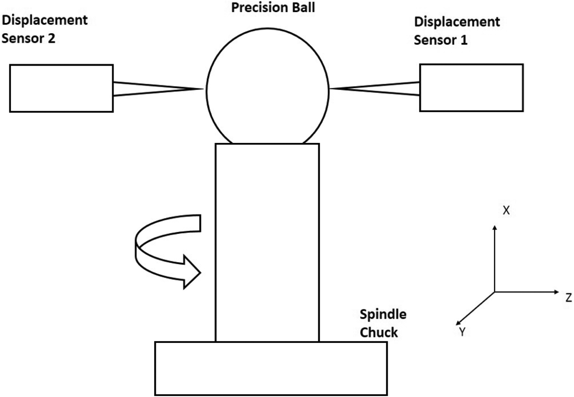
Dual-probe arrangement.
Equation (10) is the Fourier transform of the out of roundness of a ball
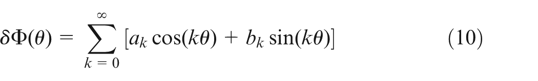
It contains a constant term with k = 0 and terms with their harmonic coefficient k = odd integers or even integers. A dual-probe arrangement with a separation angle of 180° can eliminate all odd terms by summing the data from the two probes directly. All odd terms in equation (10) will be eliminated.
Experiment and result analysis
To study the feasibility of measuring the rotating displacement, and hence the roundness of ultra-precision ball using laser focus deviation probes, an experiment setup with a displacement measuring probe based on laser focus deviation and a high-precision air bearing spindle is used. Both laser focus deviation probes are home built and calibrated with a Polytec PI P-611.1 nanopositioning stage. The position accuracy of this nanopositioning stage is 1 nm with 1σ. An ABR-120pro spindle from AcroBeam is used with specified radial run out of up to 50 nm under air pressure range of 0.4–0.6 MPa. As a testing target, a precision ceramic ball with diameter of 50 mm is used in the experiment. The ball has a rated maximum out of roundness of 70 nm. The setup is shown in Figure 7.
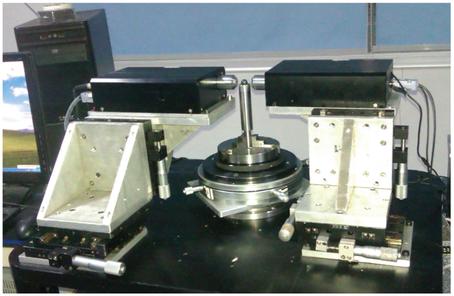
Experiment setup of laser focus deviation probes measuring rotating displacement of a precision ball. 15
To align the probe with spindle axis, the objective lens on the probe was removed, allowing the collimated laser beam to emit from the probe. A 1-mm diameter pinhole was placed over the exit laser beam. Lower the probe to allow the laser beam to hit the spindle chuck surface and observe the beam spot reflected from the chuck surface to the pinhole surface. Adjust the chuck’s tip/tilt until the reflected beam spot (slightly elongated in y direction) at the x-direction almost coincides with the pinhole with the estimated error of less than 0.5 mm, which corresponds to about misalignment of 0.6°, a less than 1% of displacement measurement error.
After carefully aligning the two probes and adjusting the center of the spindle chuck with the ball to have the spindle rotating center and the ball bearing center aligned, the residual misalignment is minimized.
The measurement data are collected by the two probes. The data acquisition system has a 16-bit data acquisition card to convert analog displacement signals from the probes into digital form. The spindle speed is set at 10 r/min, and the acquisition data rate is set at 61,440 samples/s with each recorded data averaging over 36 data points to record 10,240 data points per revolution. Figure 8 shows the displacement in one revolution from one probe.
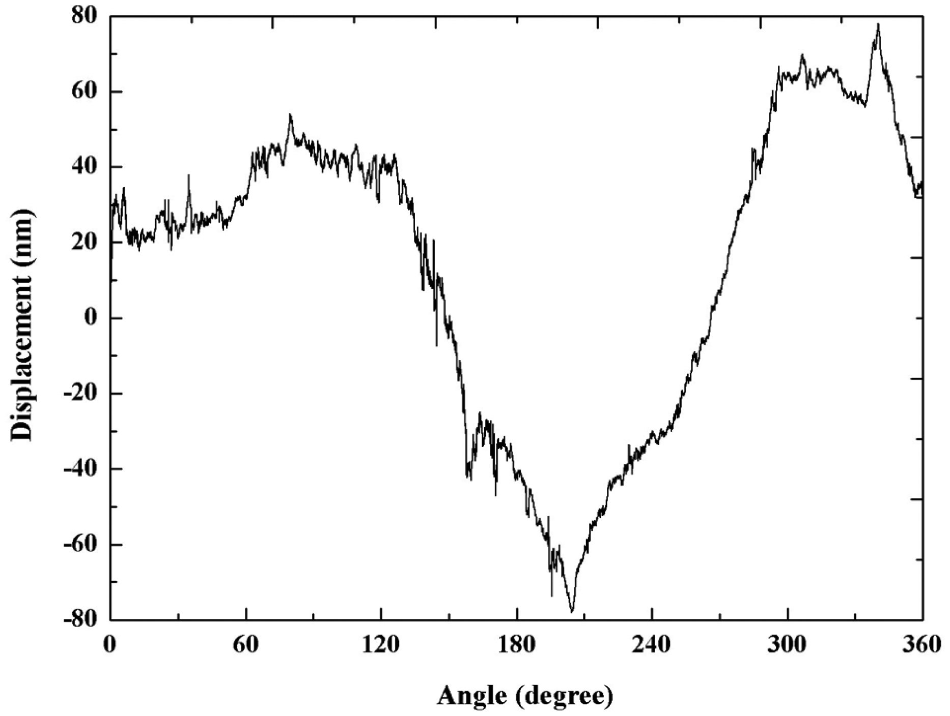
Displacement in one revolution from one probe.
The data were processed with a low-pass filter with a window size of 37 counts. Figure 9 shows the displacement results from the two probes.
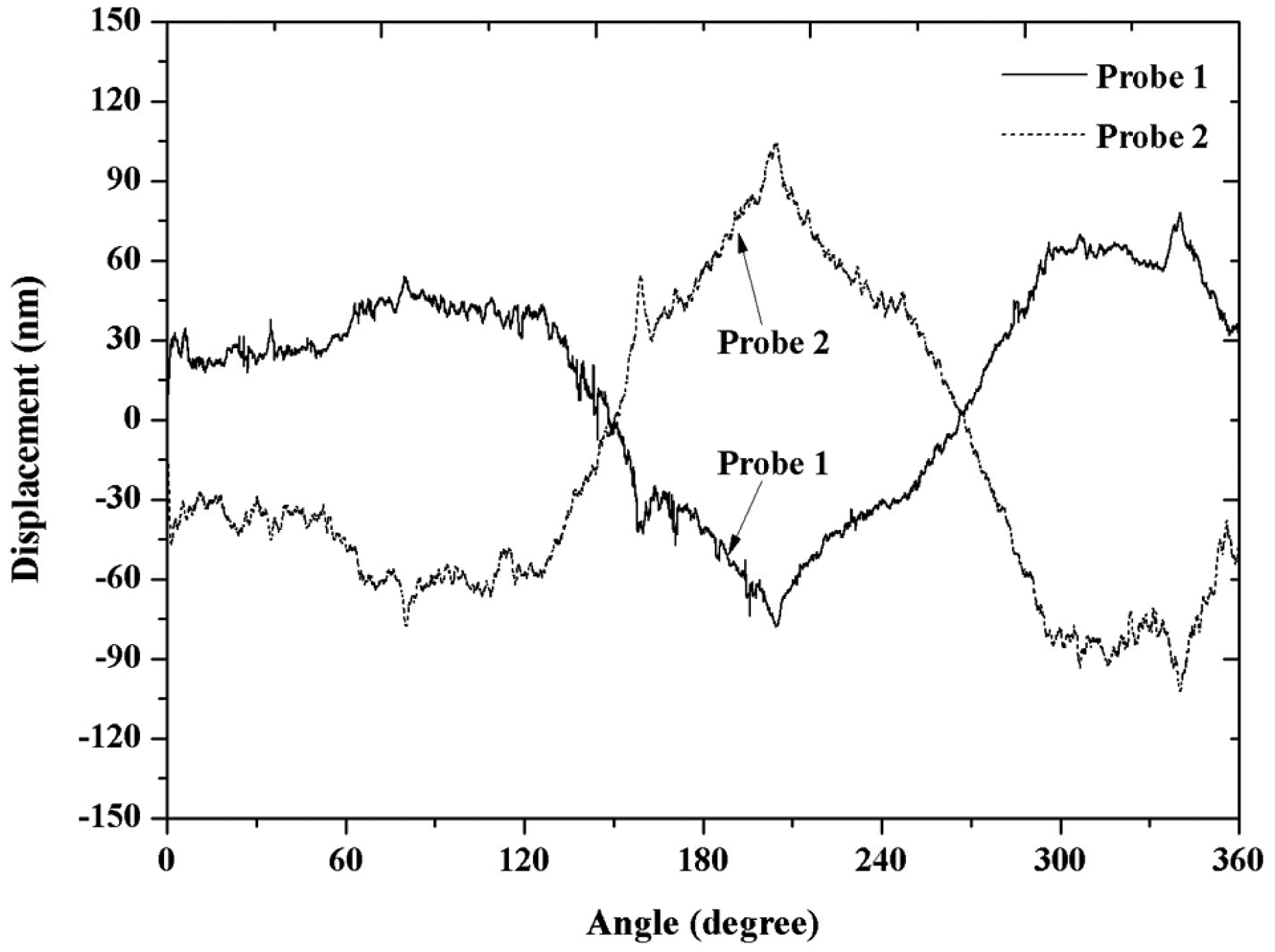
Displacement data from both probes.
The two curves clearly show a 180° phase shift. The unit in vertical axis is in nanometer. The total run out exceeded 200 nm from each probe displacement measurement, which is greater than the sum of the maximum peak to valley (PV) out of roundness of the ball and the specified maximum spindle radial run out. This indicates that there is a significant residual misalignment between the ball and the spindle. Since misalignment error and the spindle radial vibration can be eliminated by summing the displacement data from the two probes. The two sets of data in Figure 9 were summed point by point to eliminate misalignment error as shown in Figure 10, along with the two displacement curves for comparison.
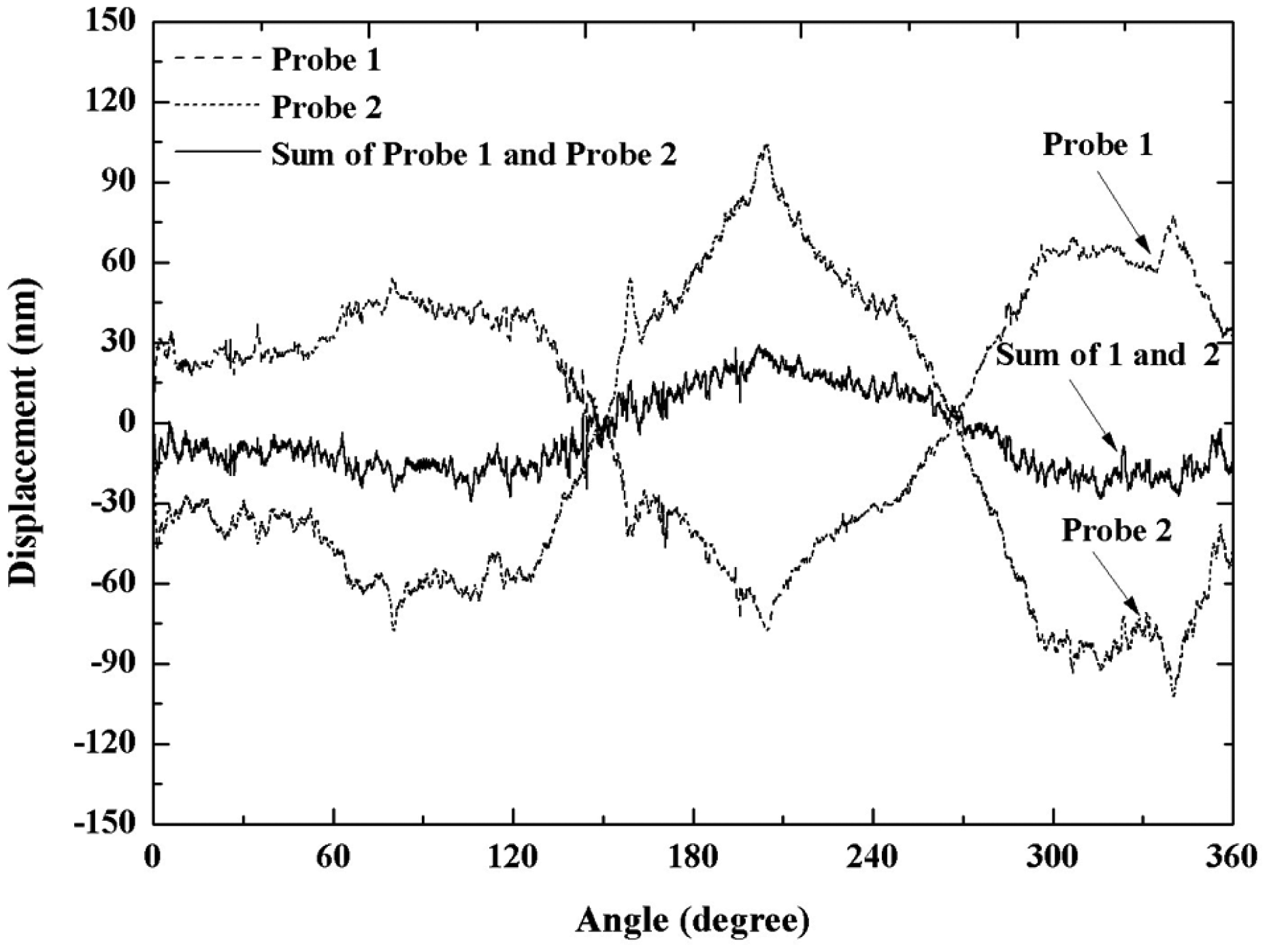
Residual displacement error after eliminating misalignment error and spindle radial vibration error.
In Figure 10, the summing of the two displacement curves represents the even terms of the Fourier transform of the roundness of the ball as indicated by equation (10). The PV value of this curve is 58 nm, which is much smaller than the maximum out of roundness value of the ball (which is specified to be 70 nm). This is expected since (1) the results only contain the even terms of the Fourier transform of the roundness and all odd terms are dropped and (2) the equator may not pass through the plane that has the maximum out of roundness of the ball. The error from (2) shall be much smaller compared to (1) as discussed in section “Ball rotating displacement measurement alignment error.”
The lateral resolution can be determined by the probe focus spot diameter, data sampling rate, and the rotating speed. In this case, the data sampling rate and the rotating speed are the determining factors of the lateral resolution. With 10,240 data points covering a circumference of 157 mm, the lateral resolution is estimated to be 15 µm, which is much greater than the estimated focused laser beam spot diameter of 3.3 µm at the ball surface.
To assess the repeatability of this measurement arrangement, multiple rounds of measurements were carried out to evaluate the displacement standard deviation from one probe at each angular position. Figure 11 shows the results.
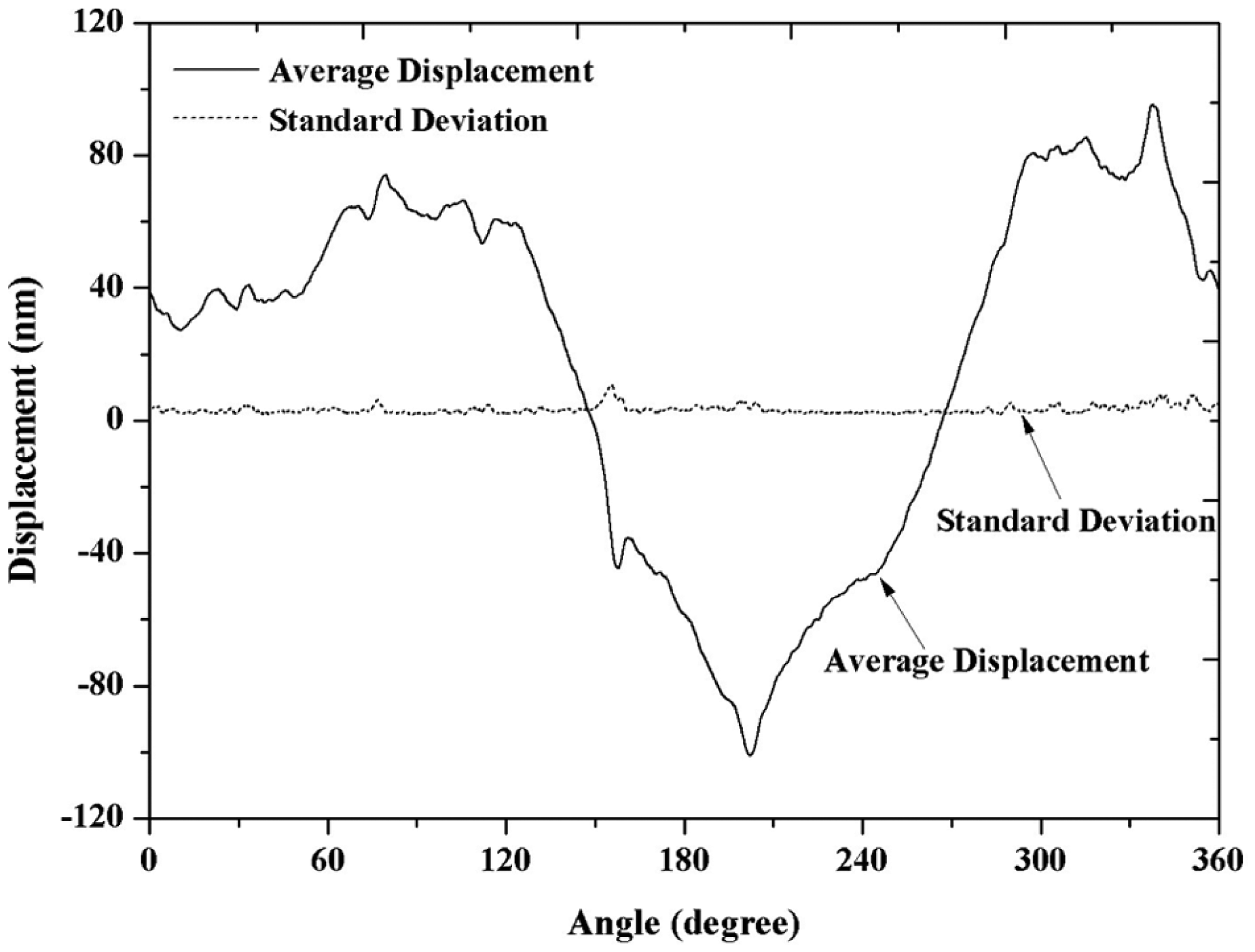
Measurement repeatability.
The displacement curve is the result of averaging over 100 measurements from one probe. The standard deviation curve is the result of the measurement standard deviation at each angular position from the same probe over 100 consecutive measurements. The maximum standard deviation from this curve is 9 nm, which occurred at where the displacement has a sudden jump. If this jump is removed, the maximum standard deviation will be 6 nm. Figure 11 shows that the probe has excellent repeatability. It should be pointed out that the measurement environment temperature variation is within 1 °C, which may cause the artifact under measurement to change its diameter by as much as 170 µm due to thermal expansion; however, the repeatability measurement indicated that the standard deviation is less than 10 nm. This may be explained by the fact that the 100 consecutive measurements were completed in 10 min; during that time frame, the average environment temperature change is much less than 0.1 °C.
Comparing this displacement curve with the displacement curves in Figure 9, the averaged displacement curve is much smoother. The high-frequency noises from both the spindle radial vibration and system noise from the probe are greatly suppressed.
Conclusion
The experiment results indicated that the laser focus deviation probe has excellent measurement sensitivity and repeatability in measuring rotating displacement of a ball. With a high-precision ball as a calibration standard, such setup is capable of measuring roundness of a ball and is suitable for high-throughput production applications. The displacement data from both focus deviation displacement probes are quite consistent. The dual-probe arrangement can serve as a process quality control for in situ applications to achieve 100% ball diameter variation inspection with high throughput and high consistency. The setup can also measure surface roughness with lateral resolution of 15 µm and height resolution in nanometers. The measurement repeatability is better than 10 nm with 1σ. The dual-probe arrangement can effectively eliminate errors introduced by misalignment and spindle radial vibration and obtain diameter variation or even terms of Fourier transform of a ball profile with a single measurement. It should be noted that environment temperature variation will introduce absolute displacement measurement errors that could be as much as a few hundreds of nanometers; however, the ball’s radial displacement variation be much less than that if the measurement can be completed in a time frame that is much less than the thermal equilibrium time required for the artifact under measurement.
Footnotes
Appendix 1
Declaration of conflicting interests
The author(s) declared no potential conflicts of interest with respect to the research, authorship, and/or publication of this article.
Funding
The author(s) disclosed receipt of the following financial support for the research, authorship, and/or publication of this article: This research was sponsored by the Joint Research Fund for Overseas Chinese Scholars and Scholars in Hong Kong and Macao (No. 51228501) from National Natural Science Foundation of China. Special thanks goes to Haining Corhai Technologies Co., Ltd for assisting developing the focus deviation probes.