
Abstract
Tungsten inert gas welding is extensively used in aerospace applications due to its unique ability to produce higher quality welds compared to other conventional arc welding processes. However, most tungsten inert gas welding is performed manually, and it has not achieved the required level of automation. This is mostly attributed to the lack of process knowledge and adaptability to complexities, such as mismatches due to part fit-up and thermal deformations associated with the tungsten inert gas welding process. This article presents a novel study on quantifying manual tungsten inert gas welding, which will ultimately help intelligent automation of tungsten inert gas welding. Through tungsten inert gas welding experimentation, the study identifies the key process variables, critical tasks and strategies adapted by manual welders. Controllability of welding process parameters and human actions in challenging welding situations were studied both qualitatively and quantitatively. Results show that welders with better process awareness can successfully adapt to variations in the geometry and the tungsten inert gas welding process variables. Critical decisions taken to achieve such adaptations are mostly based on visual observation of the weld pool. Results also reveal that skilled welders prioritise a small number of process parameters to simplify the dynamic nature of tungsten inert gas welding process so that part variation can be accommodated.
Introduction
Tungsten inert gas (TIG) welding of metals and alloys is extensively used in aerospace industries due to its ability to produce weld joints of superior quality than most other conventional arc welding processes. 1 Being a fusion welding process, TIG is highly complex and involves numerous key process variables and is mostly performed by skilled manual welders. Despite the merits of manual TIG welding process in the manufacture of aerospace components in general, a negative aspect with it is the shortage of skilled manual welders and more importantly health and safety concerns.1,2
Attempts to develop a straightforward robotic TIG welding solution for aerospace components in the last decade have failed to achieve the desired weld quality. 3 Studies indicate the lack of process knowledge and adaptability as the major weaknesses of robotic TIG welding. 3 Most of the existing welding robots (such as spot welding robots) perform pre-programmed tasks in assembly lines which have less variation within the parts and the process.4,5 Such operations do not require much intelligence and adaptability as the decisions can be pre-programmed. However, applications such as welding of aerospace components involve complex three-dimensional (3D) shaped components and require considerable real-time attention to any minor process variation. This is an issue with the existing robotic welding systems, as their capabilities are limited in real-time sensing and decision making. Furthermore, for any successful automation, the process fundamentals need to be understood in the context of automation. Most of the existing literature on TIG welding concentrates on understanding the basic physics of the TIG welding, including the study of weld pool shape,6–8 torch position 9 and the effect of process parameters on weld quality,10,11 without any emphasis on automation. Robot-assisted manual welding 12 has only been explored by a few researchers. However, these studies fail to provide adequate information on automation of TIG welding. Liu et al. 13 discuss a neuro-fuzzy-based human intelligence model for controlling weld penetration and have been used successfully in pipe gas tungsten arc welding (GTAW) process described by Liu and Zhang. 14 However, the controller has been used to control only the welding current signal. Although the control model has been tested for closed-loop control, no evidence was presented on using the model with a robotic welding system. Liu and Zhang 15 have presented a different approach where a remotely controlled welding system is developed which can work with the skilled welder. The developed system was used for actual welding trials with satisfactory results. However, it requires the involvement of the skilled welder at all times. Psychologists have also attempted to understand the human welder’s behaviour through task decomposition, but again they fail to provide any quantitative data16–19 which are essential for automation.
In this work, an experimental investigation of manual TIG welding was initiated to study the human welder actions that will eventually aid automation of TIG welding. The parameters and the critical tasks used by various welders were analysed to understand the human welder behaviour in responding to variations through controlling the TIG welding process.
Methodology
Quantitative data were collected through manual TIG welding, and statistical techniques were used to analyse the data. Interviews were carried out to collect qualitative data and were correlated with quantitative data. All the experiments were carried out according to the ethics guidelines in the Code of Human Research Ethics of the British Psychological Society. 20
Sampling method, materials and participants
To get a better understanding of human behaviour during TIG welding, manual welders with various skill levels were chosen (as shown in Table 1), and various sets of welding studies were performed.
Criteria for defining skill levels for testing.
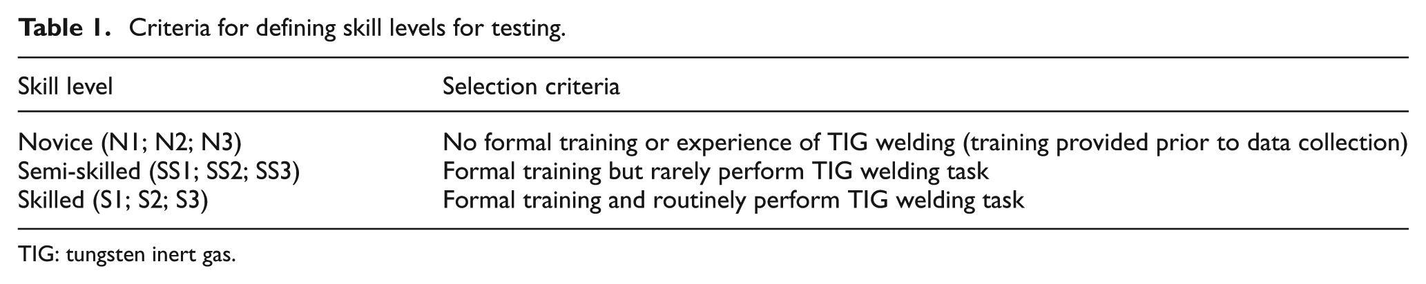
TIG: tungsten inert gas.
Due to individual differences between the welders, more than one welder representing each skill level was used for the study. Three welders were selected representing each skill level. Due to the extensive usage with both manual and robotic TIG welding, stainless steel (316l) work-pieces with dimensions of 200 mm × 50 mm × 1.5 mm were used as the work-piece, with 1.6 mm diameter filler rod. Four joint configurations, butt weld with 1 mm constant gap, butt weld with varying gap (from 1 to 3 mm), lap weld with zero gap and fillet weld with zero gap, were used during the experimentation. These four configurations were selected so as to cover a range of complexity, which will enable better understanding of human behaviour in challenging welding conditions. Four trials were performed for each set of experiments, which lasted between 1 and 2 h. A discussion session was conducted after each experiment to interpret the process parameters and methodologies used by the welders.
Experimental setup and testing method
A block diagram of the experimental setup is shown in Figure 1. The TIG welding machine used for the study is a Fronius MagicWave 4000 welding set with pure shield argon. As shown in Figure 2, an imaging development system (IDS) camera (UI-5240SE) was used to record the actions of each welder, and LabVIEW image processing toolkit was used to automatically extract the weld angles at various weld positions. It should be noted that weld angles were only considered in the x–z plane (welding path direction in Figure 2), as the movement of the torch and filler wire in y-direction (perpendicular to travel direction and normal to the work-piece) is insignificant.
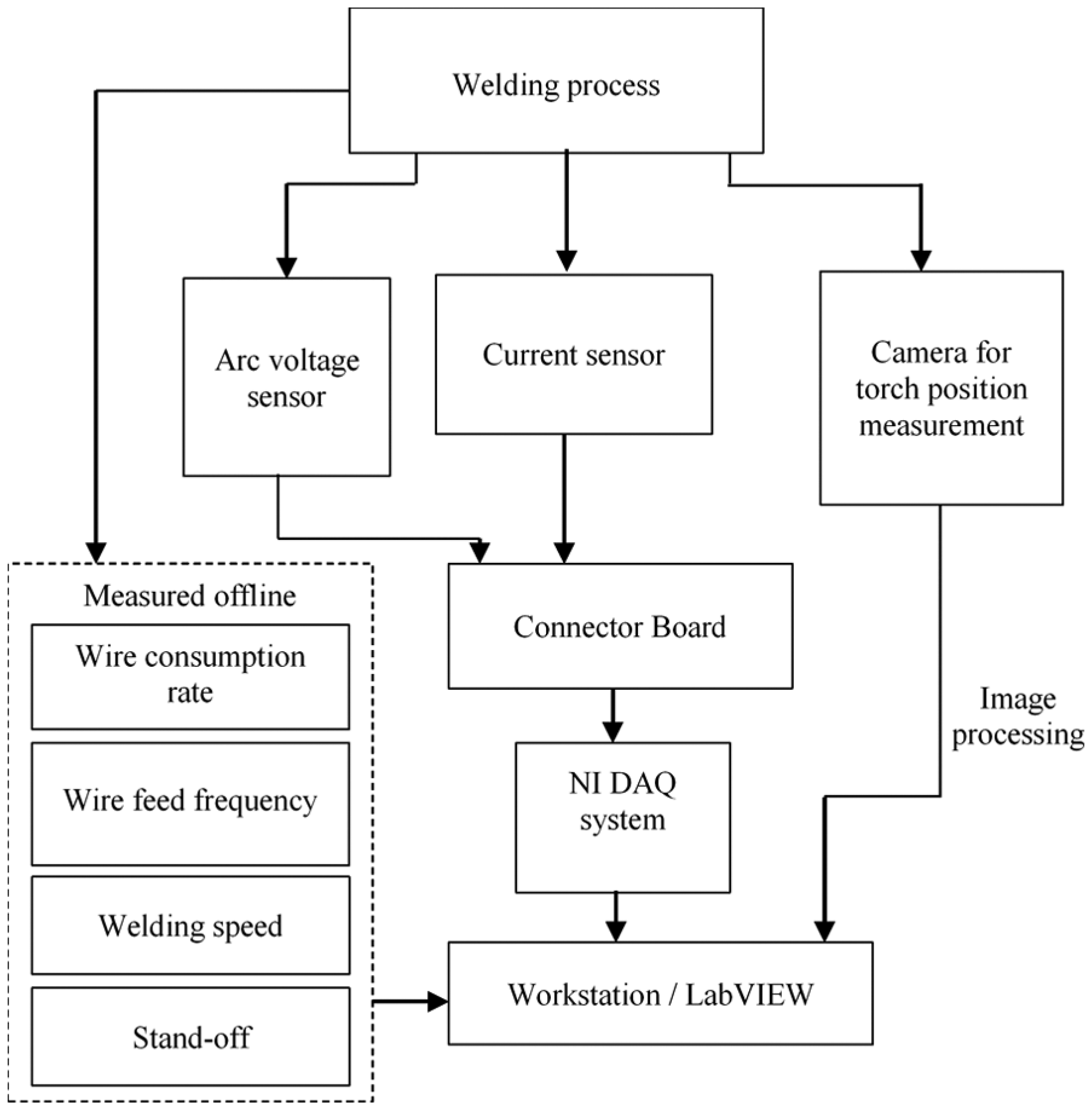
System diagram of the experimental setup.
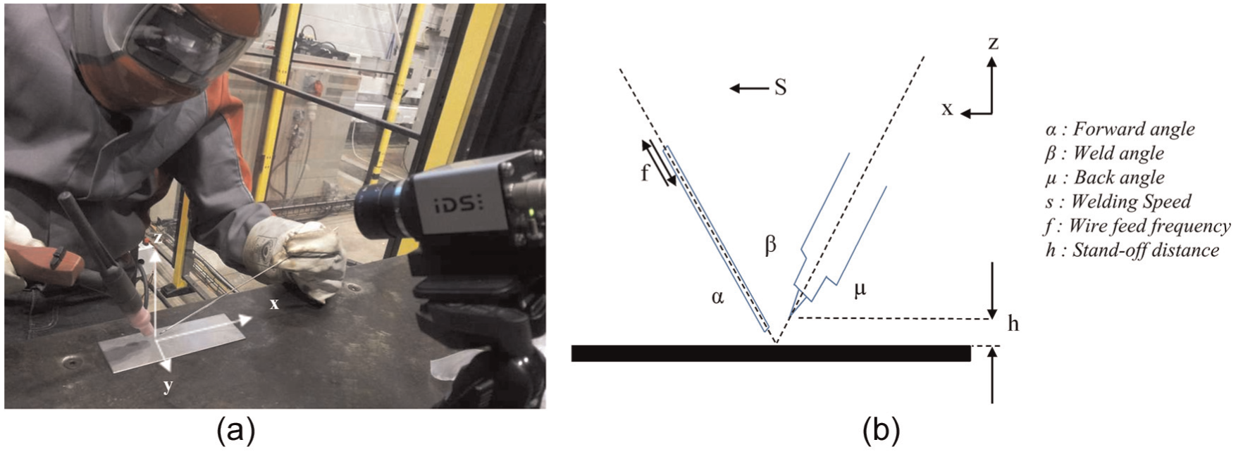
Experimental setup used for weld angle measurement: (a) photographic view of the camera setup and (b) torch and filler wire position definition.
Welding current was measured using a Hall Effect current sensor with a resolution of 1 A, and welding voltage was measured between the opposite polarities of the welding machine with a resolution of 0.1 V. The welding current was controlled by operators’ foot pedal. As shown in Figure 1, all the data were logged simultaneously into a personal computer through a National Instruments data acquisition system at a sampling rate of 1 kHz. A low-pass filter was used to filter any noise generated from the system. Average welding speed was calculated as the ratio between weld length and weld time. Difference between the length of the filler wire before and after the experiment gives the filler rod consumption, and the ratio between the total number of filler wire movements into the weld pool (obtained from the video) and total welding time gives the average wire feed frequency.
Results and discussion
Process parameter variations for different welded joint types have been measured. The process parameters such as voltage, current, speed, wire feed frequency and wire consumption rate used by various welders for various joint configurations are presented in this section. All these parameters are compared against different skill levels. Qualitative results from the interview sessions are also discussed in this section.
Effect of welding skills on process parameter control
Figure 3 illustrates the average and standard deviation in voltage observed for various skill levels with a constant gap butt weld. As seen from Figure 3, novices have higher average voltage and standard deviation compared to the other two skill levels. This is mostly attributed to the variations in stand-off distance during the welding process (welding voltage is proportional to torch stand-off 21 ). The other two skill groups have achieved an acceptable voltage level, compared to novice welders. This suggests that any voltage variation which can occur due to robot vibration should be kept at minimal. The welder S2 used a unique technique of oscillating the current using the foot pedal, which has affected his performance on maintaining consistent stand-off distance. This has resulted in relatively higher standard deviation in voltage for S2 compared to other two skilled welders (S1 and S3).
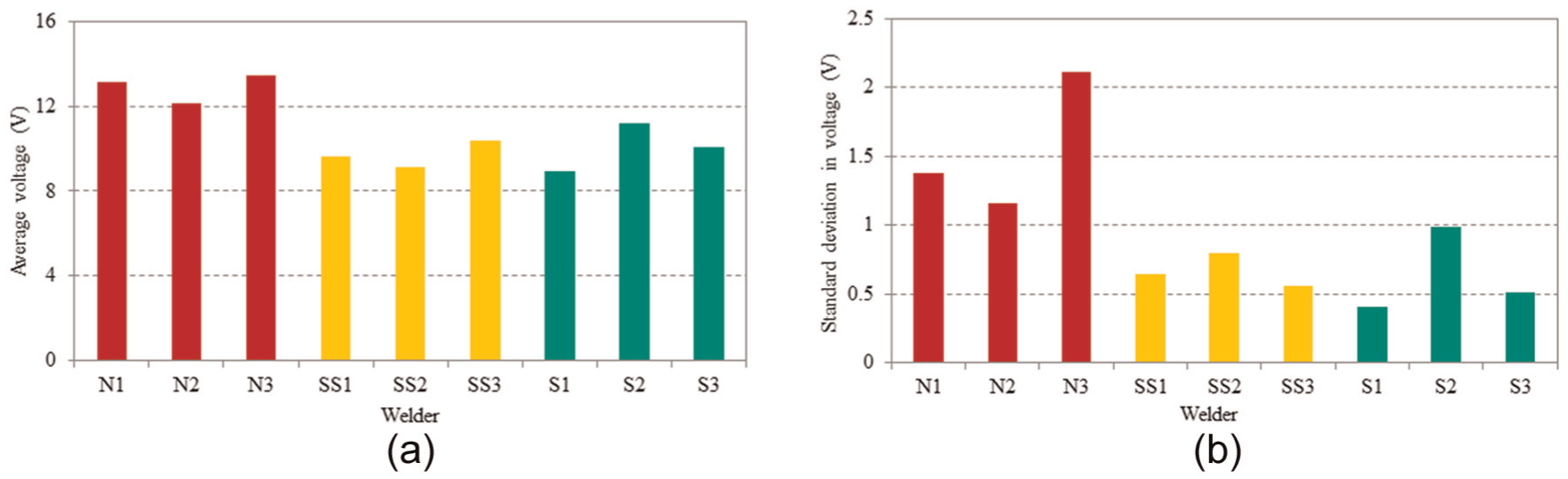
Voltage values observed for different skill levels: (a) average voltage and (b) standard deviation in voltage.
Figure 4(a) and (b) shows the average welding current and respective standard deviation maintained by different welders. As noted, all the welders have used similar range of welding current; however, the standard deviation shows significant variation between the skill levels. This variation can be explained on basis of the need for simultaneous control of more than one process parameter during the welding process, such as control of welding current and wire feed rate. The novice welders have used constant current during the welding process (lower standard deviation) and have focused on controlling other parameters (such as torch position). However, the skilled welders have controlled most of the parameters (S1-varying current, constant gap, optimal torch position, etc.) and have demonstrated the need for simultaneous control of more than one parameter. This result confirms that the TIG welding is a complex process and any automation attempt should consider simultaneous control of multiple parameters.
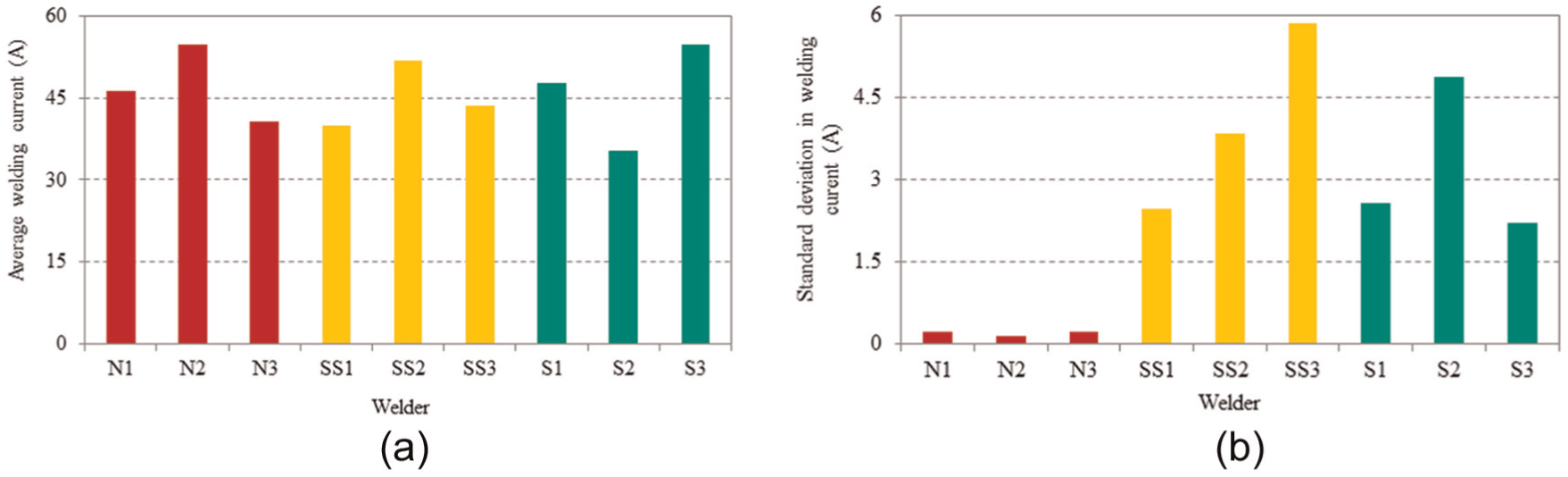
Current values observed for different skill levels: (a) average welding current and (b) standard deviation in welding current.
Figure 5(a) shows the average welding speed observed with various welders. As can be observed from the figure, novice welders had moved the welding torch faster than higher skilled welders. Figure 5(b) shows the standard deviation in welding speed. As noted from the figure, the novice welders had higher standard deviation in welding speed because of their incapability to control the torch and move at such low speed. Post-weld interviews indicate that it was difficult for the novice welders to hold the torch for a considerable period. This resulted in poor weld quality and irregular weld bead shape along the weld. This result suggests that the weld bead shape significantly depends on the speed, and automation of TIG welding should consider visual observation of the melt pool characteristic.
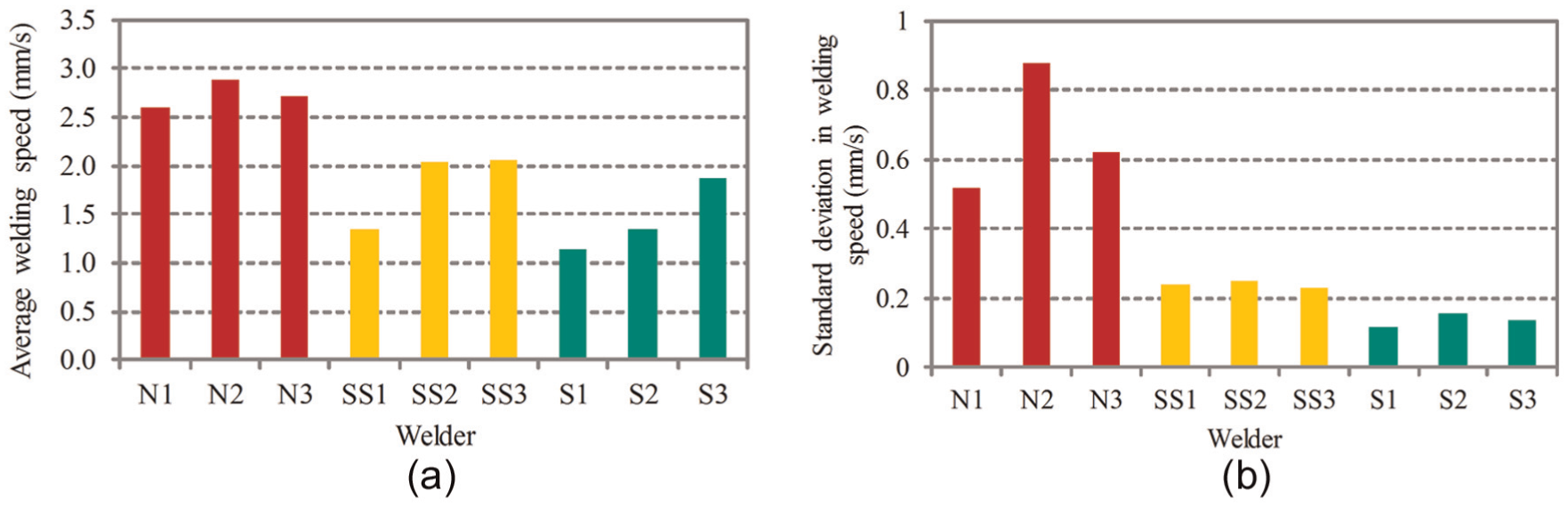
Average welding speed observed for different skill levels: (a) average welding speed and (b) standard deviation in welding speed.
Figure 6 shows the filler wire feed frequency and consumption rate observed for different skill levels. As noticed from Figure 6, novice welders used lower wire feed frequency compared to semi-skilled or skilled welders; however, the novice welders have consumed more filler wire than other welders. This is contradictory since it was expected that filler wire consumption increases with higher feed frequencies (it was observed from videos that the feed amount does not vary significantly). Videos also showed that novices feed the filler wire into plasma arc, whereas the skilled welders feed the filler wire into the melt pool. Feeding of filler wire into the melt pool results in more uniform weld bead and should be taken into consideration as a critical task for TIG welding automation.
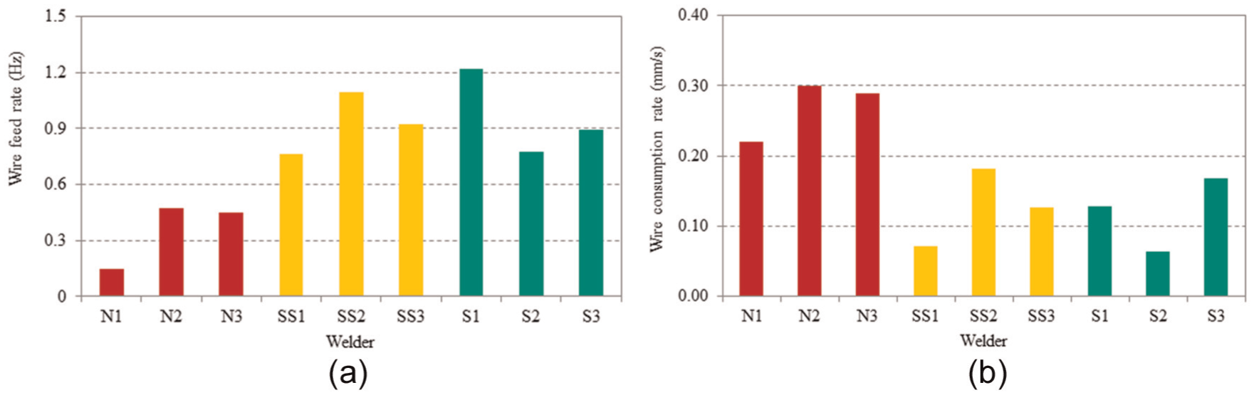
Values obtained for filler wire feed frequency and consumption rates: (a) filter wire feed frequency and (b) filter wire consumption rate.
Figure 7(a)–(c) shows the photographic view of the welders with different skill levels. As seen from Figure 7(c), the skilled welder monitors the process very closely (head position much closer to the weld zone) and maintains a comfortable position to visualise the weld pool compared to other welders. Visualisation of the weld pool and subsequent adaptive control of parameters are significant in TIG welding and should be considered largely in automation. Weld angles are also important in maintaining a proper weld pool shape and better gas shielding around the weld. For a good weld, it is recommended to have the following weld angles –α: 60–85, β: 80–90 and µ: 15–30. 21 As noted in Figure 8, only skilled welder maintains the weld angle within the acceptable range.
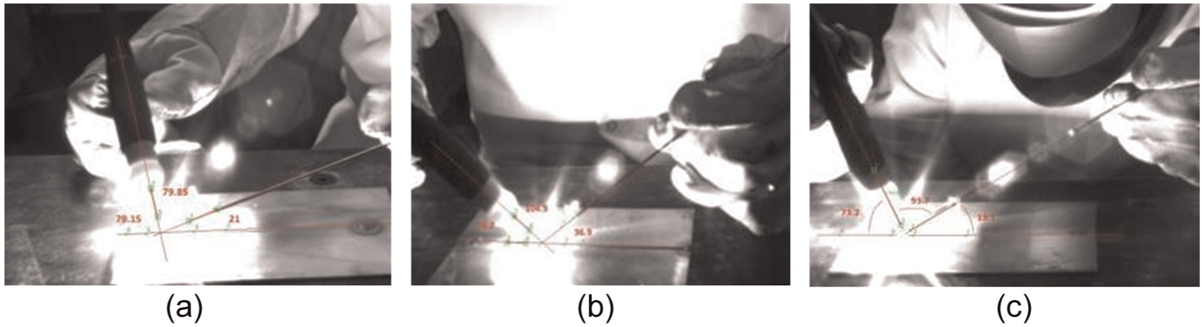
Torch filler wire angles for different skill levels: (a) novice welder, (b) semi-skilled welder and (c) skilled welder.
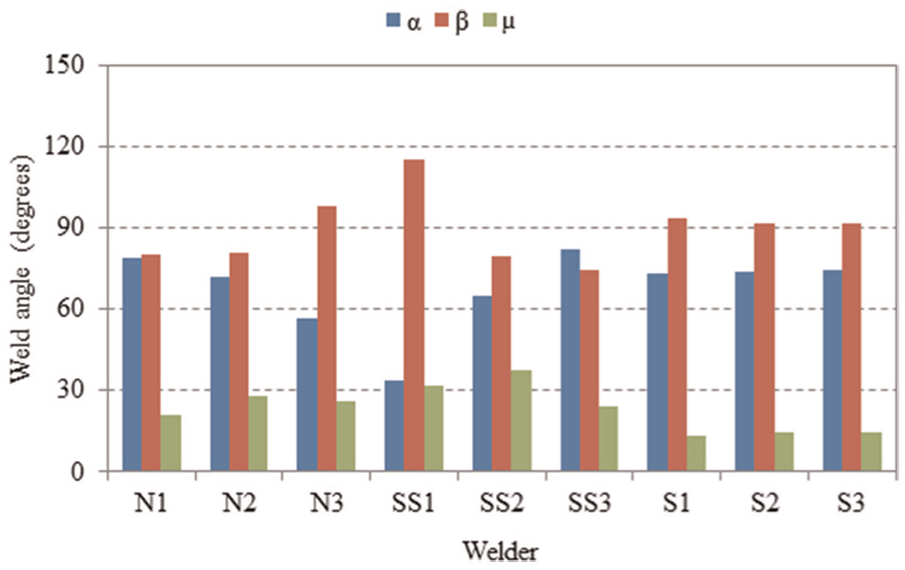
Torch filler wire angles for different skill levels.
Effect of skills on weld quality
To study the significance of skill level on the weld bead quality, the weld produced by various manual welders (constant gap butt weld) was assessed for visual imperfections. Figure 9(a)–(c) shows the photographic view of the welds and the corresponding parameters (current and voltage) produced by a novice, semi-skilled and skilled welder, respectively.
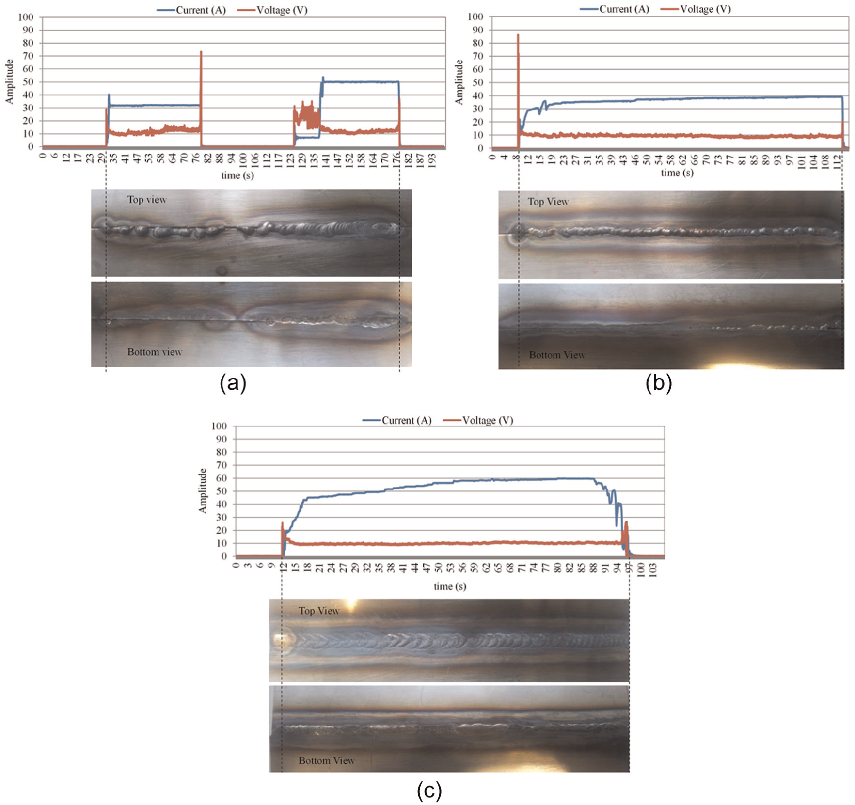
Welds completed by different welders: (a) novice welder, (b) semi-skilled welder and (c) skilled welder.
As can be seen from Figure 9, the weld produced by the novice welder was of poor visual quality compared to other two skill levels. This is closely attributed to the level of control exerted by the welders over the welding process. Unskilled welders maintain a constant current throughout the welding process, whereas the skilled welder changes the current to maintain the weld bead profile. Compared to the novice and semi-skilled welders, the skilled welder has managed to control the rate of change of welding current at the start and stop of the weld to avoid burn-through. These strategies need to be considered for successful automation of TIG welding.
The skilled welder also maintains a more consistent voltage (by keeping better control of stand-off distance), adequate penetration and uniform bead width, which helps achieve the desirable weld quality. Figure 10 shows the load extension graphs obtained from a tensile testing machine for each skill level. According to the results, clearly the skilled welder produces significantly maximum load. However, the load at maximum tensile extension is almost similar for each skill group. Adaptive decision made by skilled welders has resulted in significant effect on the weld strength.
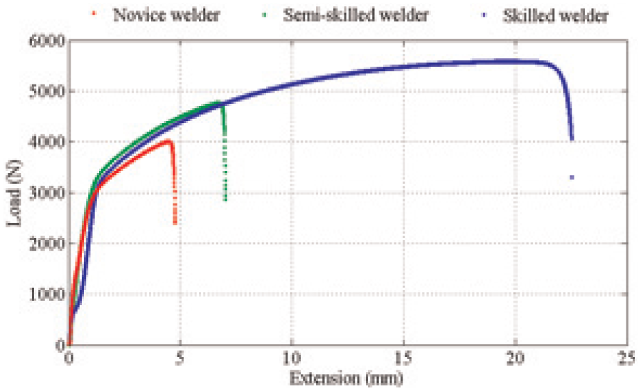
Load-extension graphs for different skill levels: (a) novice welder, (b) semi-skilled welder and (c) skilled welder.
These results again confirm that the automation of TIG welding requires significant level of adaptive decision making (or control) to achieve better weld quality.
Effect of joint complexity on process parameters
Weld joints with various complexities were used to study the welder’s adaptability with different welding scenarios. It is expected that the welding of complex geometries requires highly adaptive control of process parameters. Skilled welders have a better understanding of the range of parameters to be used, which they closely follow. However, unskilled welders make random decisions due to lack of welding knowledge.
Figure 11 shows the wire feed frequency, speed, welding current and voltage, respectively, used by the welders for various joint configurations. As can be seen from the figures, the novice welder attempted to change all the parameters irrespective of the weld complexity; however, the skilled welder has selectively controlled the parameters. For example, the novice welder uses a broad range of speeds (1.5–3.25 mm/s) for various weld configurations, whereas the skilled welder (1.1–1.4 mm/s) maintains similar speed levels for various weld configurations. The skilled welder prioritises changing the current and wire feed frequency compared to speed and voltage, which is essential to achieve a good quality weld. 22 This confirms that the adaptive control of the TIG welding automation system should consider prioritising welding current and wire feed frequency.
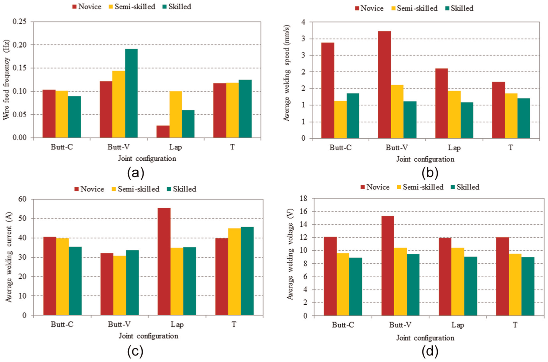
Process parameters used for various joint types: (a) wire feed frequency, (b) average welding speed, (c) average welding current and (d) average welding voltage.
Analysis based on post-weld interviews
To interpret the data observed during welding, interviews were carried out after each welding run. Videos were also observed offline and compared with the experimental results. Critical tasks, important decisions and actions were identified from the post-weld interviews. Table 2 shows the number of welders who were successful in each critical task, and as expected the skilled welders were successful in most of the tasks. The novice welders were not successful in most of the tasks due to lack of process knowledge and therefore could not make the right decisions, which is also evident from the experimental samples (Figure 8).
Results of the post-weld interviews – welder task competency.
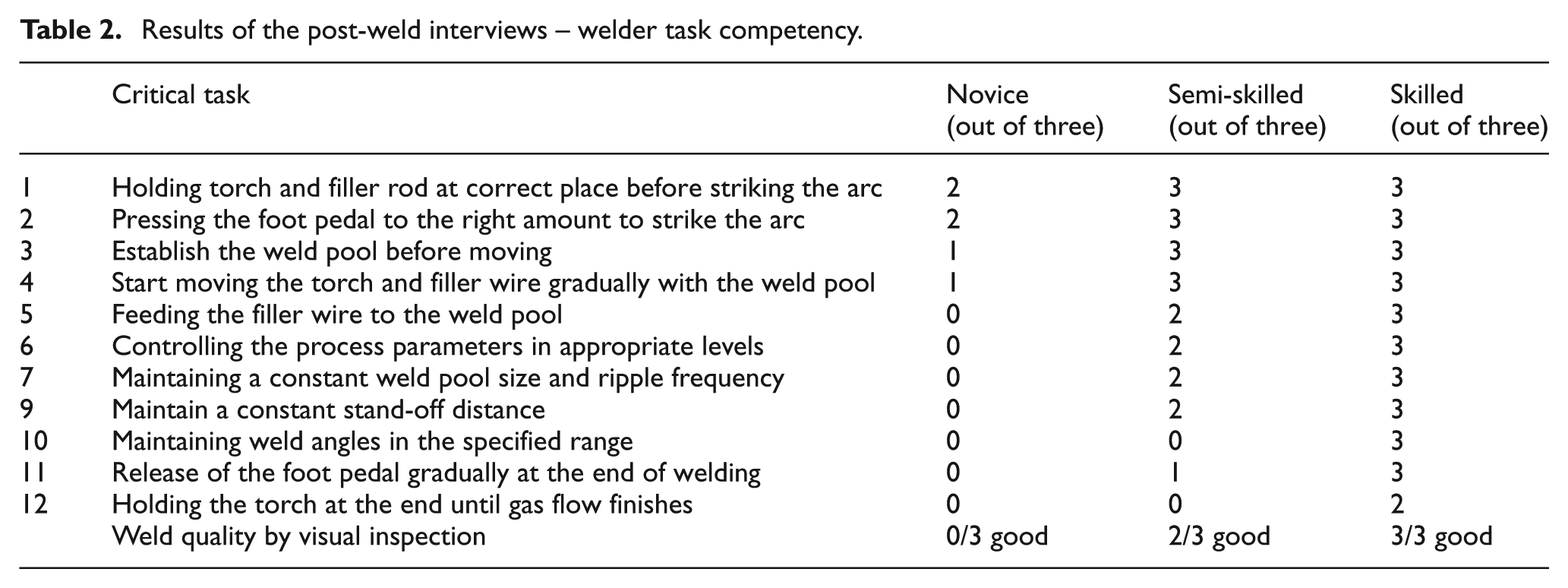
As can be seen from Table 2, failure to accomplish the critical tasks (novice: 5–12 in Table 2) can significantly affect the weld quality (Figure 8). For example, the weld pool size (task 7 in Table 2) can be maintained either by controlling the welding current or by controlling the welding speed. 19 However, the skilled welders preferred the former, as an arbitrary change of speed can result in abrupt loss of the weld pool 18 (Figure 8). These results demonstrate the need for successful completion of each critical task (Table 2) to achieve good weld quality.
Figure 12 shows the typical feedback methods used by the welders obtained from post-weld interviews. As can be seen from the figure, most of the parameters are controlled based on visual observation of the weld pool. Few welders have also used the acoustic signal from the welding arc to control the voltage and stand-off distance. The key feedback method that manual welders use is the visual information from weld pool, which again confirms the significance of visual feedback in TIG welding automation.
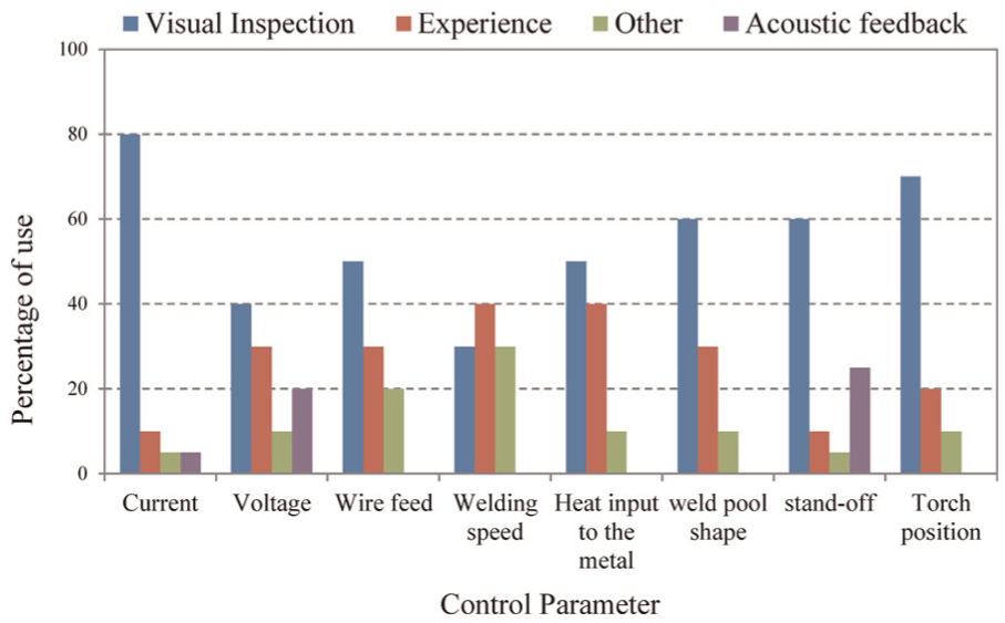
Decision making criteria for critical tasks identified in TIG welding.
Conclusion
The work reported in this article focused on understanding the manual TIG welding process, in the context of TIG welding automation. Simultaneous control of key parameters is essential in TIG welding to achieve good weld quality. Welding current and wire feed rate are the most significant parameters that need to be controlled and prioritised to account for variations in geometry. Prioritising process parameters in a similar manner to the skilled manual welder could simplify the control problem in automation. Results indicate that adaptive control of parameters is vital for successful TIG welding automation. Critical tasks in TIG welding are found to be establishing the weld pool, feeding filler wire to the weld pool and maintaining constant weld pool shape, and they are mostly controlled by visual observation. Feedback control on basis of visual information from the weld pool is essential for successful automation of TIG welding.
Although the work included within this article studied human welder behaviour based on the joint geometry and skill level for the TIG welding process, future work will be carried out to investigate the human behaviour for different material types, more complex geometry and welding process type. Future work also involves real-time feedback of the weld pool and relating the changes that human welders bring to the weld pool shape to achieve the desired weld quality.
Footnotes
Declaration of Conflicting Interests
The author(s) declared no potential conflicts of interest with respect to the research, authorship and/or publication of this article.
Funding
The author(s) disclosed receipt of the following financial support for the research, authorship, and/or publication of this article: This work was supported by the EPSRC Centre for Innovative Manufacturing in Intelligent Automation for undertaking this research work under grant reference number EP/IO33467/1.