
Abstract
Gear shaping is a widely applied technology to produce spur gears. Generally, the pinion cutter and the gear workpiece rotate uniformly with a given gear ratio during the conventional gear shaping process, which can cause a large variation of the cutting area per stroke in cutting tooth spaces. It makes the cutting force less than the rated capacity of the gear shaper in most cutting strokes and thus reduces the process efficiency. To overcome such a shortage, a new spur gear shaping method is proposed in this article, in which the cutting area per stroke is homogenized to a target value through optimizing the circular feed rate. The new method can enhance process efficiency by keeping the cutting force equivalent to the rated capacity of the gear shaper. The specific algorithm includes a number of aspects: cutting area calculation, gear profile generation, cutting area analysis of conventional gear shaping, and cutting area homogenization. Additionally, the new spur gear shaping method is demonstrated and validated using a VERICUT simulation. From the simulation results, it is found that the process efficiency is improved up to 40% via the efficient gear shaping because of the reduced number of shaping strokes. Hence, the new spur gear shaping method is applicable for computer numerical control gear shapers to improve the process efficiency significantly without any additional hardware changes.
Keywords
Introduction
Spur gears with involute tooth profile are widely used gears, which are the most common components of mechanical transmission. Typical cutting methods of spur gears include shaping, forming, hobbing, and shaving, as shown in Figure 1.1,2 Among these methods, gear shaping is versatile for internal gears, external gears, stepped gears, and segment gears and is theoretically error free due to its equivalency to meshing of a pair of gear and pinion.
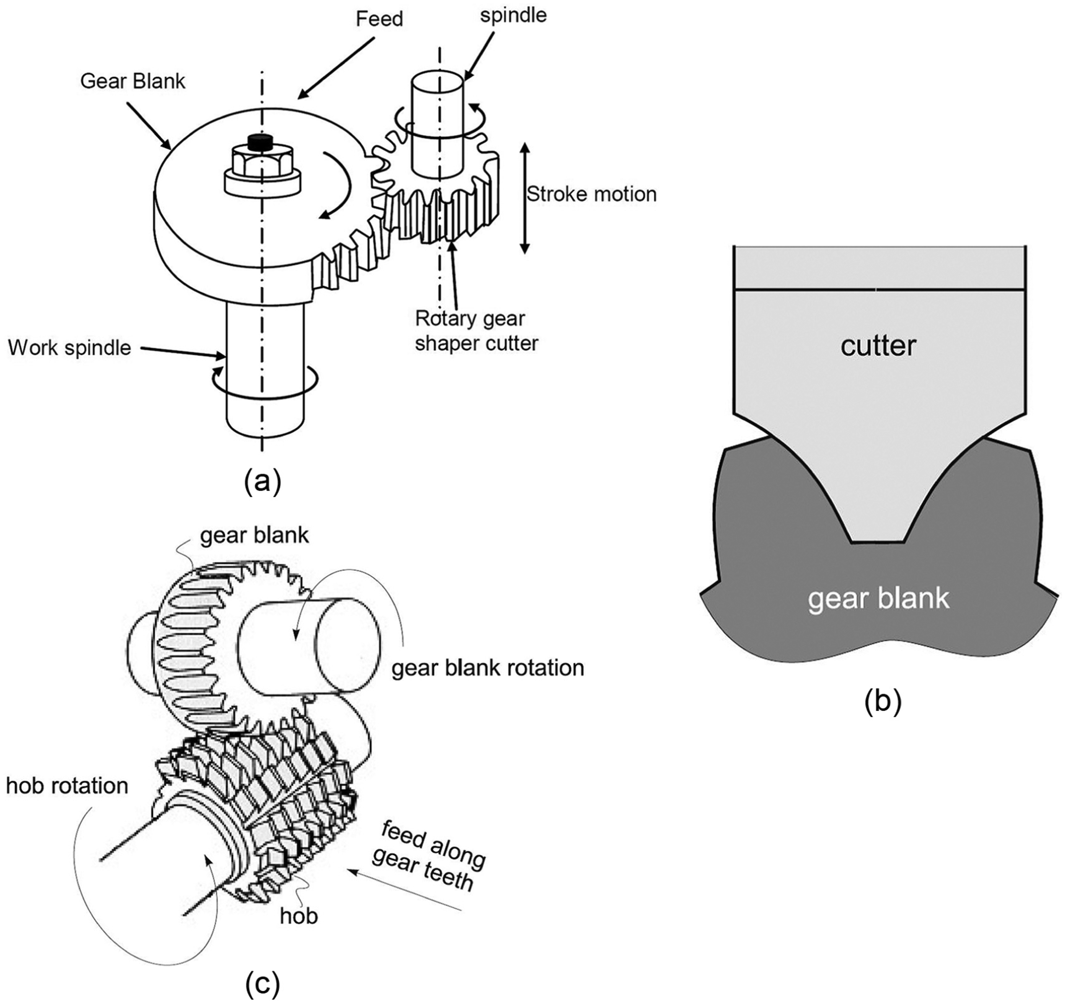
Typical cutting methods of spur gears: 2 (a) shaping, (b) forming, and (c) hobbing.
Efficiency is essential to mass production of gears. The efficiency of gear shaping can be enhanced in two ways: (1) application of high-speed cutting and (2) exploitation of potentiality of gear shapers.
High-speed gear shaping has been applied in industry since 1960s. At present, the strokes per minute of high-speed gear shapers can be more than 2500 str/min, and the maximum cutting speed can be faster than 100 m/min. 3 However, high-speed gear shaping is appropriate for manufacturing of small and modest gears but not suitable for large gears because of the high inertia of the gear workpiece and the gear shaper.
In conventional gear shaping, the shaper cutter and the gear workpiece rotate uniformly with a given gear ratio, which results in a large variation of the cutting area per stroke in cutting a gear groove, as shown in Figure 2. It is found that there are only about 1/3 strokes whose cutting area is close to the maximum in a machining cycle (the period that the pinion cutter or the gear workpiece rotate an angular pitch), which makes the cutting force less than the rated load of the gear shaper in most cutting strokes and cannot make the best use of the capacity of the gear shaper. This effect becomes more significant for large gear shaping whose working efficiency is hard to be enhanced by increasing spindle speed. Rokkaku et al. 4 proposed an improved gear shaping method, which enhances the process efficiency by keeping the cutting area (cutting force) of all strokes at the rated capacity of the gear shaper through controlling the radial feed rate. Nevertheless, the method is not practical due to the following drawbacks: (1) frequent and short reciprocating motion will worsen local wear between the screw and the guideway of the radial feed system of the gear shaper, and (2) the backlash of the screw will cause impact. These drawbacks will weaken the accuracy and the service life of the radial feed system or even cause crack damage of the pinion cutter by the backlash impact. Liang et al. 5 proposed a multi-axis plunge milling method, which removed the material with high efficiency by regulating the feed rate to keep material removal rate (MRR) constant. However, the method is not applicable to gear shaping.
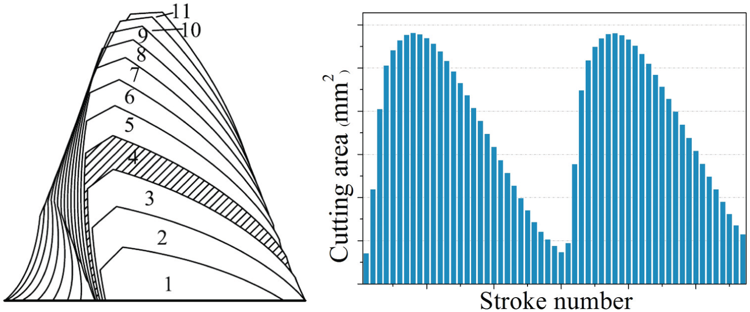
Schematic illustration of cutting profile and area distribution of conventional gear shaping.
Moreover, the potentiality of gear shapers or machine tools can be exploited via process control with computer numerical control (CNC) technology. Two control strategies, namely, adaptive control constraint (ACC) and adaptive control optimization (ACO), have been developed to improve process efficiency.6,7 The ACC control strategy keeps a specific process variable (i.e. the cutting force or power) at a constrained value through real-time in-process regulation of process parameters.8–11 However, the ACO control strategy optimizes a process performance index (i.e. productivity or efficiency) through off-line process adjustment.12–16 Fellowes Corp 17 developed the FS180 CNC gear shaper with ACC capability in early 1990s, which realized constant cutting force processing through continuously regulating circular feed rate. Although it is effective in improving process efficiency, high-performance CNC system is prerequisite to the ACC and ACO control in addition to the complexity of their algorithms.
As discussed above, each of the current methods for improving process efficiency of gear shaping possesses has some inherent limitations. High-speed gear shaping is only appropriate for small and modest gear shapers. Rokkaku’s method 4 is still not applied in industry due to its drawbacks in practicability. Few ACO methods are used in practice because of their requirements of online measurement of tool wear.18–21 ACC methods are in poor industrial acceptance because of the lack of controller stability.16,22 The application of the hybrid adaptive control method is also limited in gear shaping because of their higher requirement to CNC hardware and algorithm complexity.
This research, in contrast to the methods discussed above, proposes an efficient spur gear shaping method for CNC gear shapers, in which the cutting area of the strokes is homogenized through optimizing the circular feed rate. It will keep the cutting force equivalent to the rated capacity of the gear shaper and significantly reduce the number of strokes. The method optimizes the circular feed rate off-line and thus improves the efficiency of gear shaping without any changes to the CNC gear shapers and additional cost.
This article is organized as follows: section “Methodology” describes the methodology; section “Case study” presents a case study on gear shaping to demonstrate and validate the new method via theoretical calculation and VERICUT simulation; and finally, section “Conclusion” draws the conclusions.
Methodology
The flowchart and schematic illustration of the algorithm of the efficient gear shaping method is shown in Figure 3. The method consists of two stages: (1) cutting area analysis of the conventional gear shaping and (2) cutting area homogenization. In stage 1, the cutting area of every shaping stroke is calculated by modeling the gear generation after setting a radial feed in terms of the geometric parameters of the pinion cutter and the gear workpiece and the radial and circular feed rates. Then, the accumulated cutting area versus the stroke number in the radial feed is formulated with a polynomial regression. Subsequently, in stage 2, the circular feed rate is optimized from constant to variational via homogenizing the cutting area of every shaping stroke to a target value. The above computation repeats until all radial feed rates are finished, which can be implemented through MATLAB and AutoCAD VBA programming.
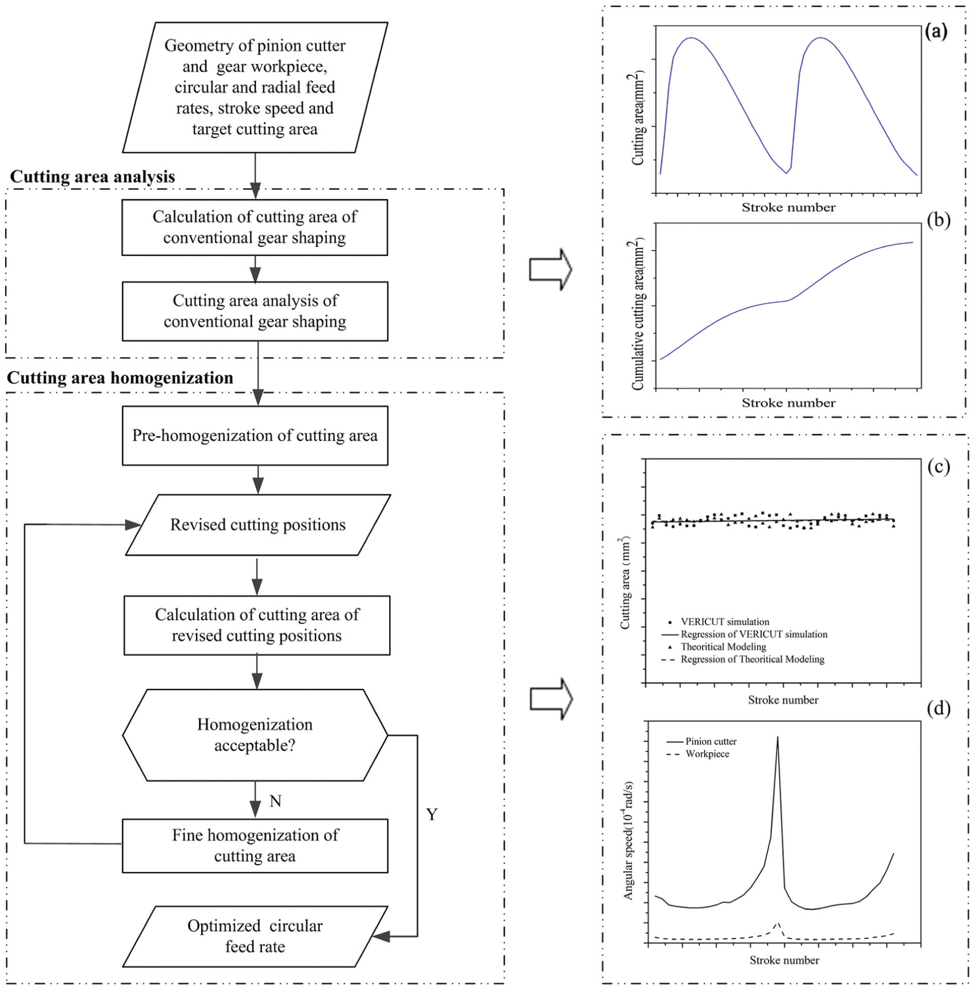
Flowchart and schematic illustration of the algorithm of the efficient gear shaping method: (a) cutting area of conventional gear shaping of the first radial feed, (b) cumulative cutting area of conventional gear shaping of the first radial feed, (c) comparison of theoretically calculated and simulated cutting areas of efficient gear shaping of the first radial feed, (d) angular speed of the pinion cutter and the gear workpiece for efficient gear shaping of the first radial feed.
Cutting area calculation of gear shaping
To simplify the calculation, the effect of the face width of the pinion cutter and the gear workpiece is ignored since the stroke speed is much greater than the circular feed rate, that is, the duration of each shaping stroke is assumed to be zero. Calculation of the cutting area of each shaping stroke is accomplished using Boolean intersection operation between the projections of the pinion cutter and the gear workpiece on the rotatory plane (i.e. the transverse plane), as shown in Figure 4. The Boolean operation can be implemented by AutoCAD VBA programming. 23 Before the Boolean operation, the pinion cutter and the gear workpiece must be correctly positioned by modeling the gear generation of gear shaping according to the given radial and circular feeds. It is also needed to model the geometry of the pinion cutter in order to conduct the Boolean operation.
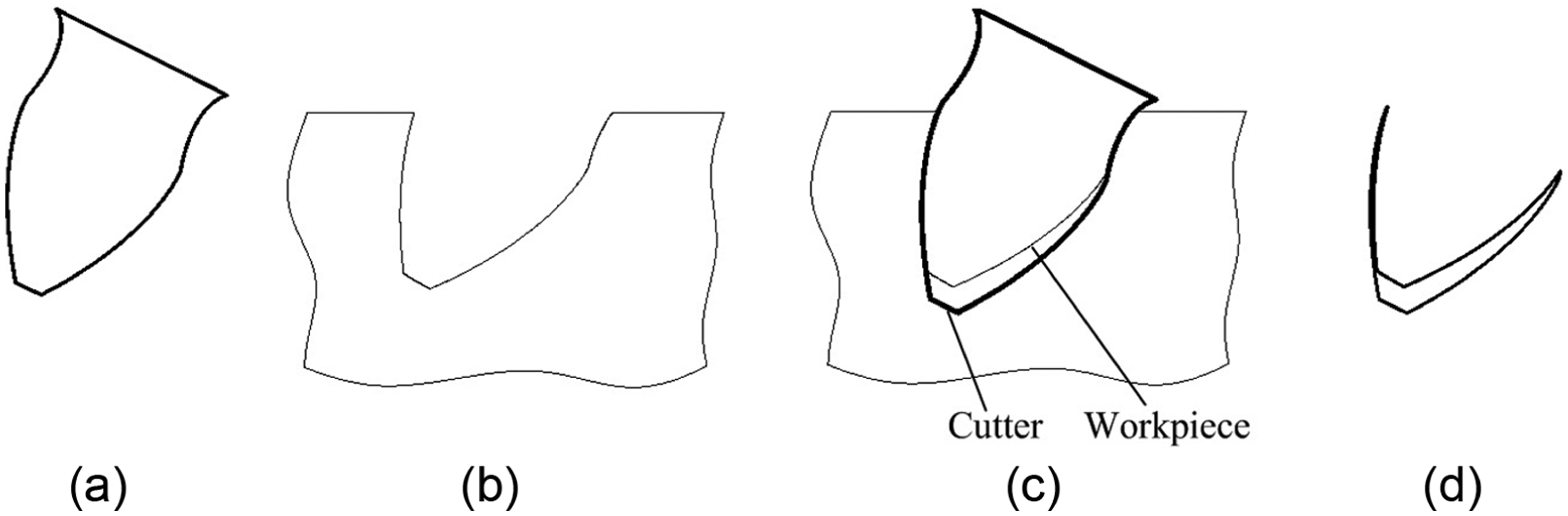
Calculation of cutting area of a gear shaping stroke (using Boolean intersection operation): (a) cutter, (b) workpiece, (c) cutter ∩ workpiece, and (d) cutting chip.
Modeling of the pinion cutter
The tooth profile error caused by the rake angle of the pinion cutter is ignored to simplify the modeling, that is, the projection of the cutting edge of the pinion cutter on the rotatory plane is the profile of an accurate pinion. As shown in Figure 5, the profile of a tooth of the pinion cutter consists of five curves: the involutes Tool1 and Tool2, the prolate epicycloid fillet curves Tool3 and Tool4, and the addendum arc Tool5. They can be represented by the following equations 24
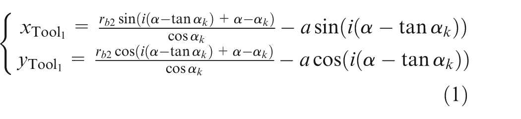
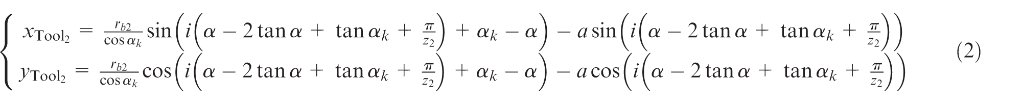


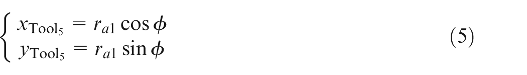
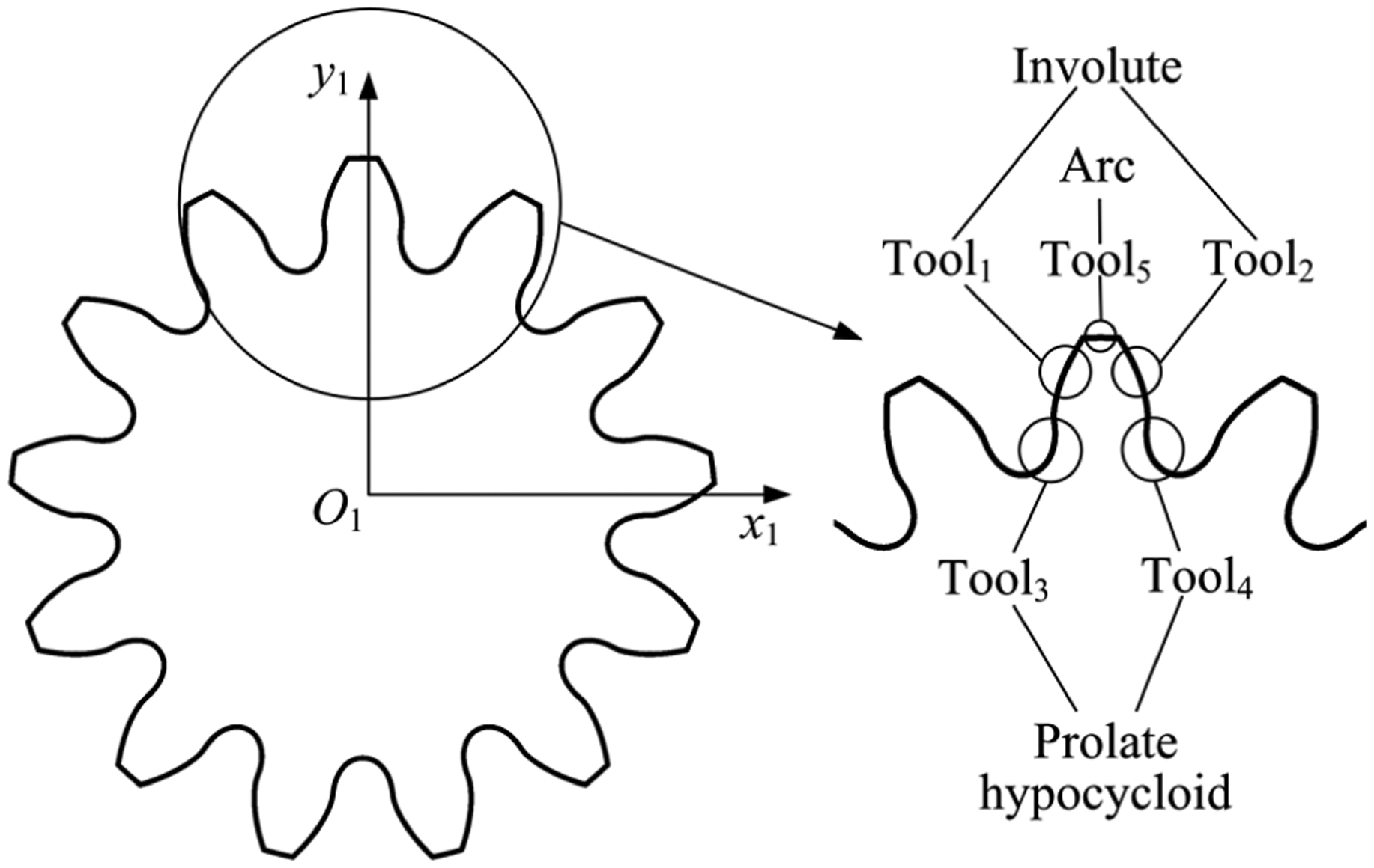
Profile of the pinion cutter.
The profile of the pinion cutter can be formed through rotatory pattern of the tooth formulated by equations (1)–(5).
Modeling of the gear generation
To model the gear generation, the coordinate systems of gear shaping are set up as shown in Figure 6, wherein Oxy is the inertial coordinate system, and O1x1y1 and O2x2y2 are the pinion cutter coordinate system and the gear workpiece coordinate system, which are fixed with the pinion cutter and the gear workpiece, respectively. Here, it is assumed that the origin of the inertial coordinate system coincides with that of the gear workpiece coordinate system. The modeling of the gear generation of gear shaping can be achieved by transforming the geometry of the pinion cutter from its coordinate system to the gear workpiece coordinate system. The transformation can be expressed as
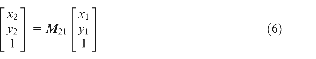
where
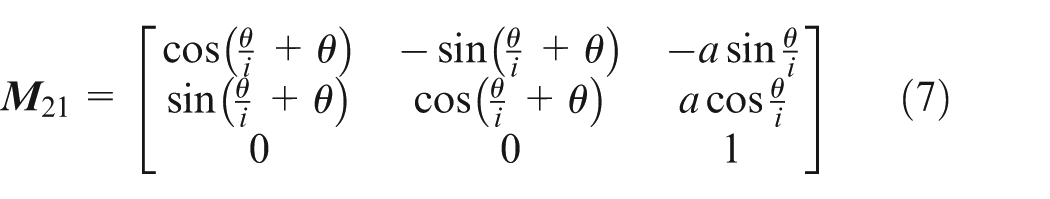
where a is the center distance between the pinion cutter and the gear workpiece, θ is the rotating angle of the pinion cutter, and i is the gear ratio between the gear workpiece and the pinion cutter.
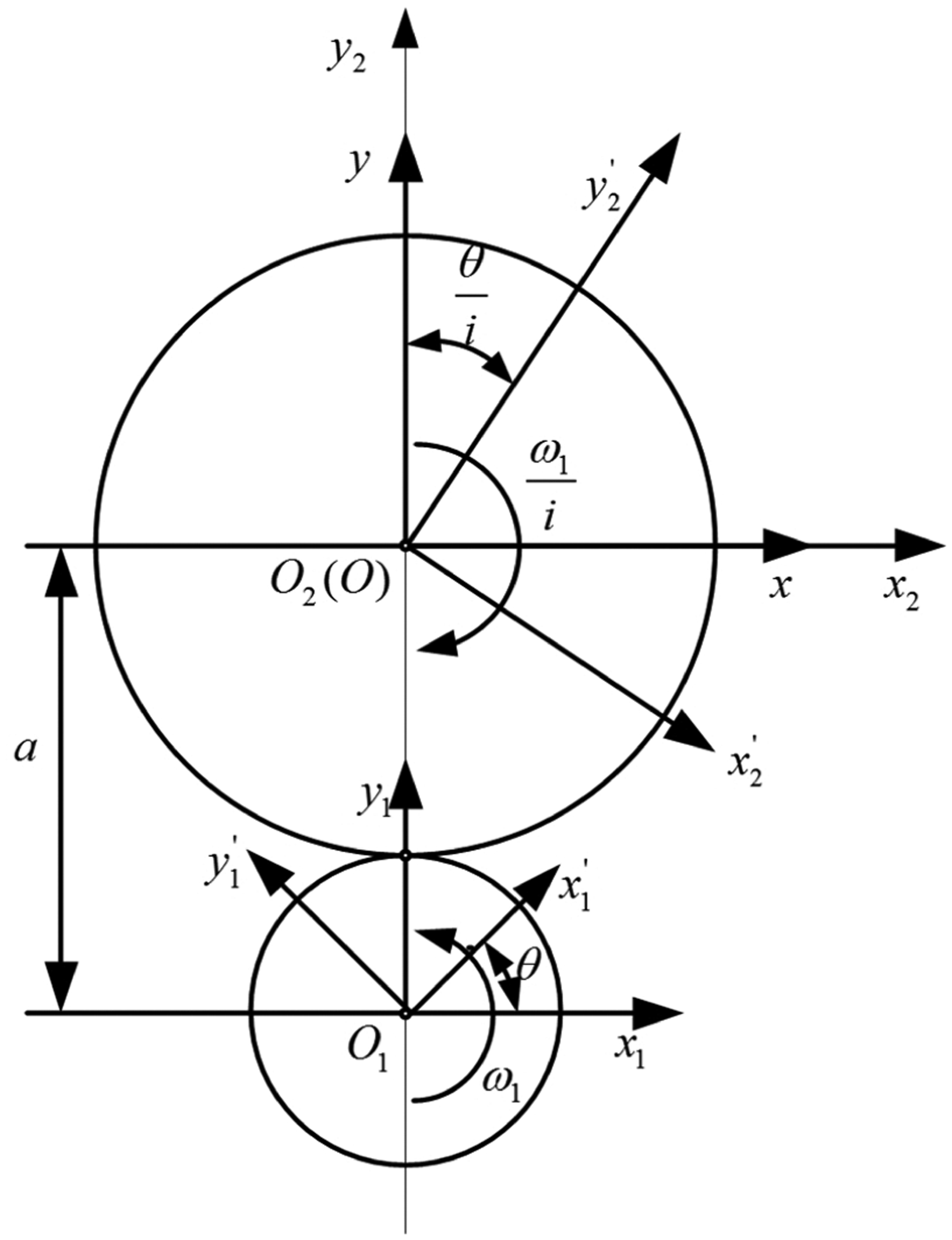
Coordinate systems for external gear shaping.
By transforming the geometry of the pinion cutter from O1x1y1 to O2x2y2 with equation (6), the tooth profiles of the pinion cutter at subsequent positions defined by a series of rotating angles θ1 = 0 > θ2 > … > θn = 2πi and all teeth of the gear workpiece will be generated at the current radial feed rate, as shown in Figure 7. Wherein every rotating angle θi (i = 1, 2, …, n) corresponds to a shaping stroke. The cutting area of every shaping stroke can be calculated using the Boolean intersection operation presented in Figure 4. Actually, in the following cutting area analysis, it is only necessary to model a complete generation of one tooth of the gear workpiece.
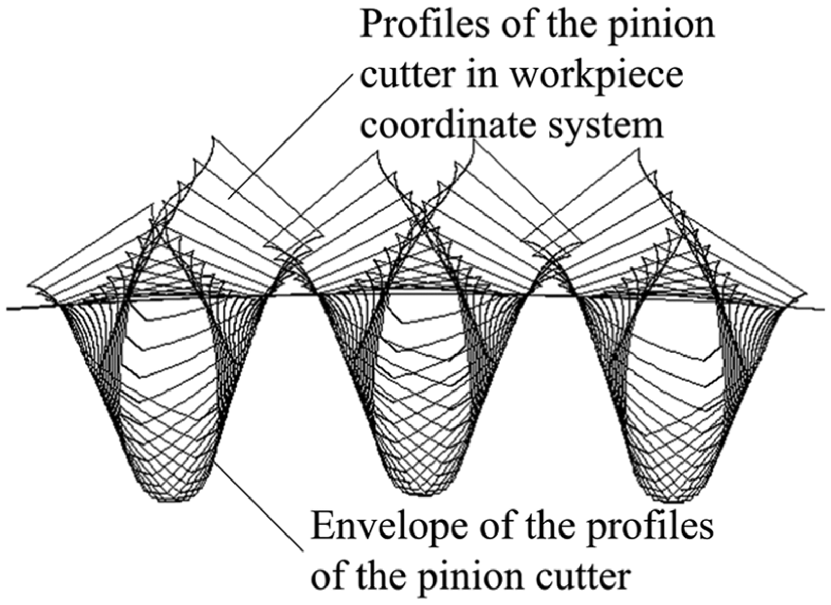
Tooth generation of the gear workpiece.
Cutting area analysis of conventional gear shaping
After calculating the cutting area Ak (k = 1, 2, …, M; k is the current stroke number; M is the total number of strokes in the machining cycles to shape the profile of one tooth) of every shaping stroke of the conventional gear shaping with a given radial feed rate, the accumulated cutting area until shaping stroke number k is finished will be
In order to explain the concept better, Figure 3(a) and (b) demonstrates the cutting area distribution and the accumulated cutting area versus stroke number.
Additionally, it should be noted that the time interval between two strokes is constant for a given number of strokes per minute since the pinion cutter and the gear workpiece rotate uniformly in the conventional gear shaping. The rotating angle θ of the pinion cutter, which indicates the cutting position of the pinion cutter and the gear workpiece (see Figure 6), is then proportional to the stroke number k of the conventional gear shaping. Thus, the stroke number k of the conventional gear shaping can be regarded as an index P of the cutting position, P = k.
Then, the accumulated cutting area of the conventional gear shaping, as a function of the cutting position, can be expressed with a polynomial of the cutting position index P as

The order N of the polynomial must be big enough to ensure the regression accuracy. Generally, it is recommended N ≥ 10. The coefficients a1, a2, …, aN+1 can be resolved with the least square method from the
Cutting area homogenization
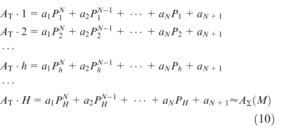
In the efficient gear shaping, cutting area homogenization is realized by regulating the cutting positions sequentially in order to update the cutting area of the strokes to a target value. For a given target cutting area AT, the cutting position Ph (1 ≤ Ph ≤ M) of shaping stroke number h (h = 1, 2, …, H) and the total stroke number H can be revised sequentially by equation (10) to homogenize the cutting area in the efficient gear shaping
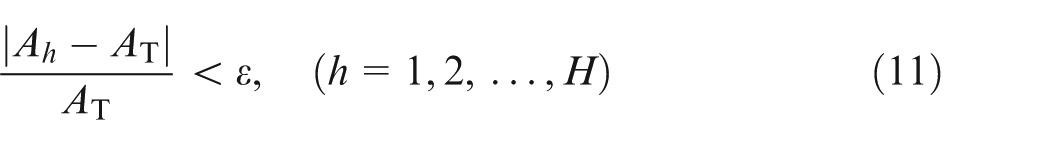
Equation (10) formulates a rough or pre-homogenization of the cutting area. The homogenization may not be acceptable through the pre-homogenization. A subsequent loop of calculating the cutting area of the revised cutting positions and fine homogenizing the cutting area is needed, as shown in Figure 3. The iterations of the loop will be ended, and the optimized circular feed rate will be outputted when the homogenization reaches the given accuracy ϵ (e.g. 5%) as
The fine homogenization of the cutting area can be implemented as follows: if the cutting area Ah at a cutting position Ph does not meet equation (11), the cutting position Ph will be revised as

where ΔP is the increment of the cutting position (ΔP = 0.01 seems reasonable from the illustrative case study in section “Case study”). The “±” operator in equation (12) will be “+” if the cutting area Ah at the cutting position Ph is less than the target cutting area AT, otherwise the “±” operator will be “−.” If the cutting area Ah meets equation (11), the cutting position Ph remains unchanged.
Following the fine homogenization, the cutting area should be recalculated with the newly revised cutting positions and also checked for the homogenization accuracy. This loop computation continues until the cutting area of all cutting positions meet the accuracy requirement given by equation (11), as shown in Figure 3(c).
Subsequently, the angular speeds of the pinion cutter and the gear workpiece can be calculated according to the finally revised cutting positions
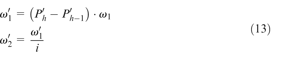
where ω1 is the angular speed of the pinion cutter in the conventional gear shaping, and
In gear shaping, the radial feed is divided into several rates to cut the whole tooth depth of a gear. The algorithm in Figure 3 will be applied sequentially from the first to the last radial feed rates to finish the homogenization of the cutting area for the efficient gear shaping. Moreover, it is necessary to set an identical initial orientation of a reference tooth of the pinion cutter for tool setting in the calculation and application of the efficient gear shaping.
Case study
The geometry and processing parameters of the pinion cutter and the gear workpiece are listed in Table 1. The gear shaping is accomplished with three radial feeds, the rate of each feed is 1/3 tooth depth of the gear. Two rotated angular pitches of the pinion cutter and the gear workpiece, that is, two machining cycles, are needed to shape the profile of one tooth. The two rotated angular pitches are supposed to be finished in 60 shaping strokes in the conventional gear shaping, which indicate the cutting positions according to the previous discussion in section “Cutting area analysis of conventional gear shaping.” The initial orientation of the pinion cutter for tool setting is illustrated in Figure 5, as marked by the direction of the coordinate axis y1.
Geometry and processing parameters of the shaper cutter and the gear workpiece.
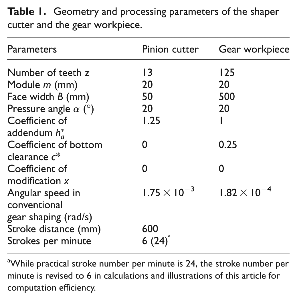
While practical stroke number per minute is 24, the stroke number per minute is revised to 6 in calculations and illustrations of this article for computation efficiency.
Theoretical modeling
Following the algorithm and procedure developed in section “Methodology,” tooth profile modeling of the pinion cutter, tooth generation modeling of the gear workpiece, cutting area calculation, cutting area analysis for the conventional gear shaping, and cutting area homogenization for the efficient gear shaping are conducted in terms of the parameters in Table 1. Figure 8 presents the tooth generation of the gear workpiece of the first and second radial feeds in the conventional gear shaping. Figures 9(a) and 10(a) show the cutting area of the conventional gear shaping in the two machining cycles of the first and the second radial feeds, respectively. The accumulated cutting areas of the first and the second radial feeds,
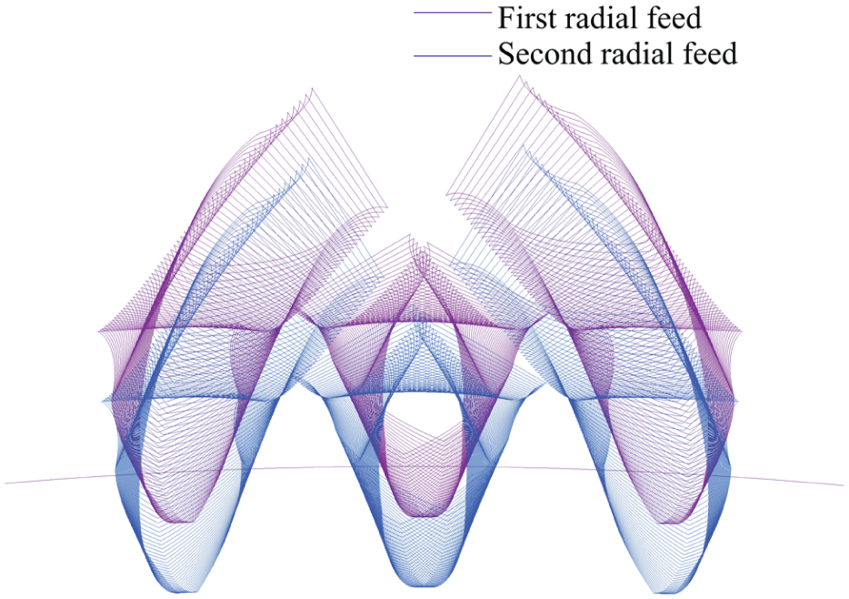
Tool path and generated tooth profiles of the gear workpiece.
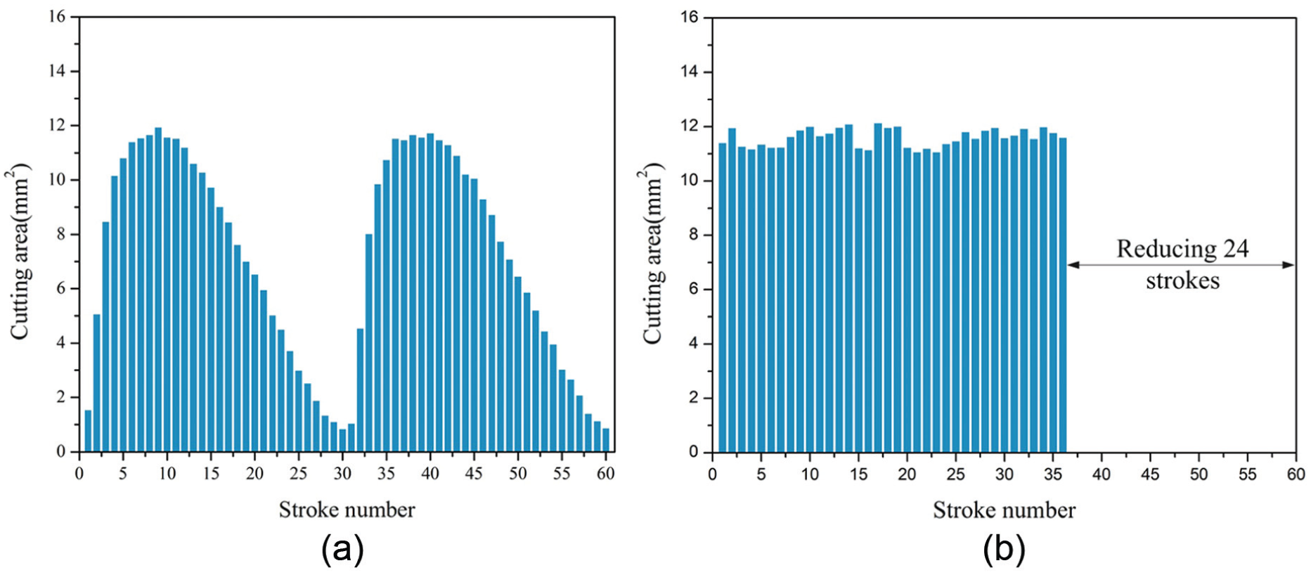
Cutting area of (a) conventional and (b) efficient gear shaping of the first radial feed.
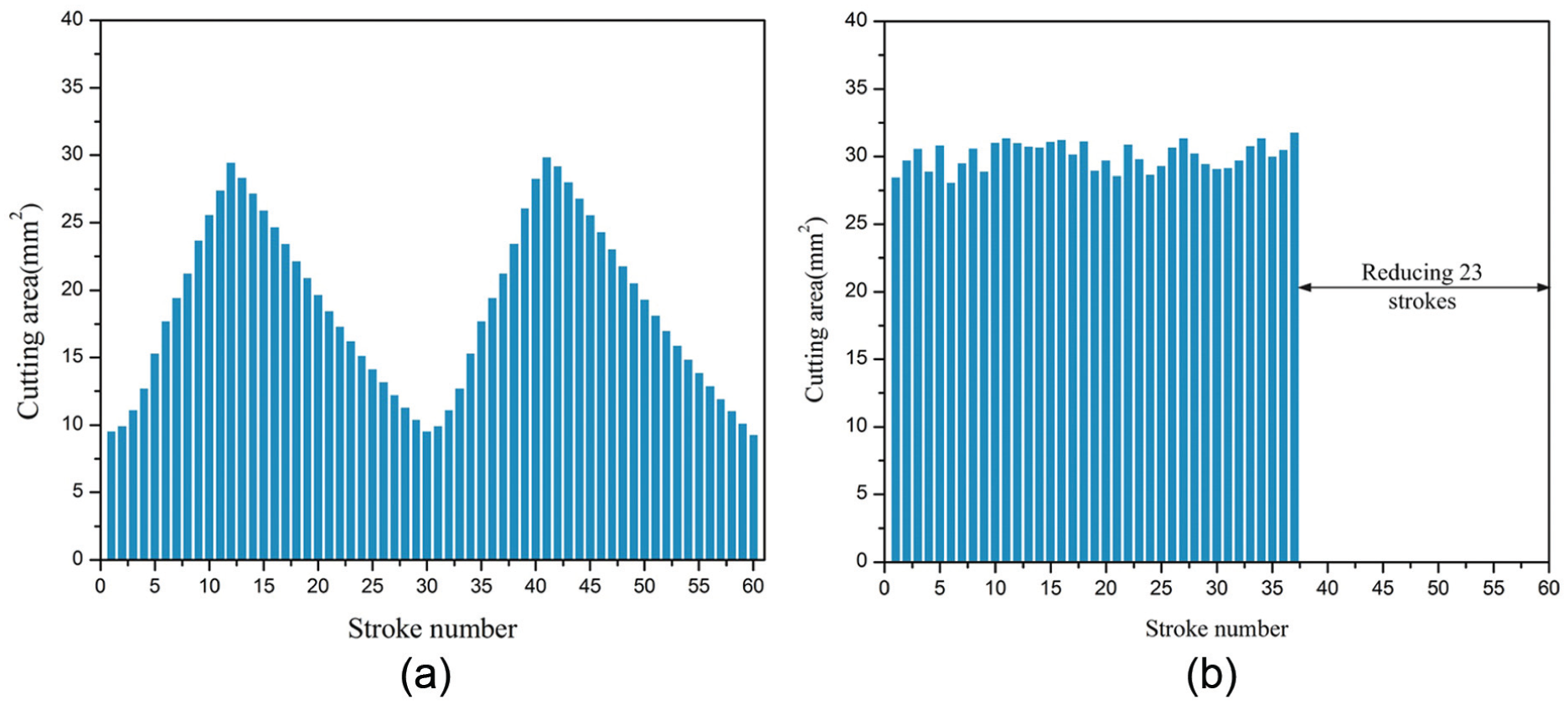
Cutting area of (a) conventional and (b) efficient gear shaping of the second radial feed.
The target values for cutting area homogenization of the first and the second radial feeds are set to the maximum cutting area of each radial feed A1T = 11.6236 mm2 and A2T = 29.8510 mm2, respectively. The accuracy of the homogenization is set to ϵ = 5%. The homogenization is implemented with the above regression equations, target values, and accuracy.
Figures 9(b) and 10(b) show the cutting area of the efficient gear shaping in the two machining cycles of the first and second radial feeds, respectively. The number of shaping strokes of the first and second radial feeds in the two machining cycles is reduced from 60 of the conventional gear shaping to 36 and 37 of the efficient gear shaping, respectively. Figures 11 and 12 present the angular speed and angular accelerator of the efficient gear shaping in the two machining cycles of the first and second radial feeds, respectively. As shown in these figures, the angular speed varies periodically with sharp peaks. The peak speed is about 6.1 and 2.6 times of the valley speed in the first and second radial feeds, respectively. The sharp peak speed means abrupt changes in the accelerator and worsens the dynamics of the gear shaper. Such peak speed should be smoothed to abate the accelerator to fit the power of the gear shaper.
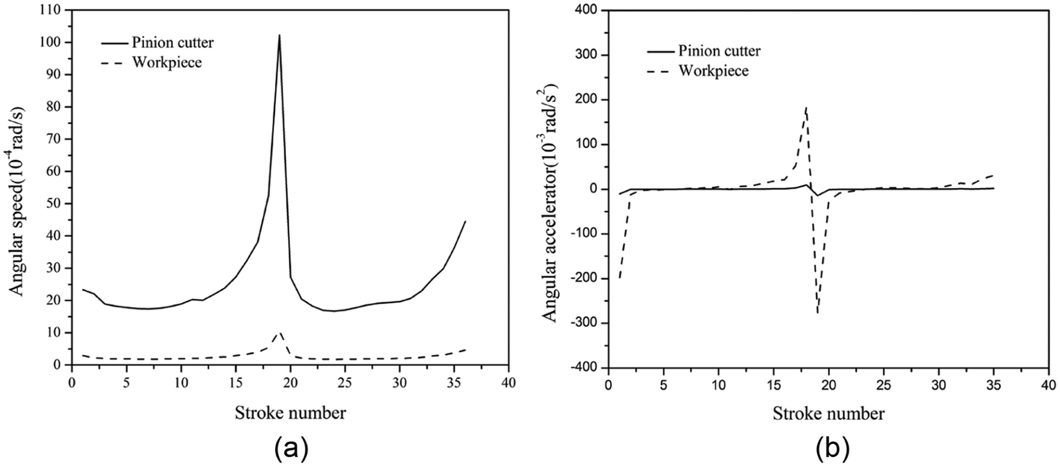
(a) Angular speed and (b) angular accelerator of the pinion cutter and the gear workpiece for efficient gear shaping of the first radial feed.
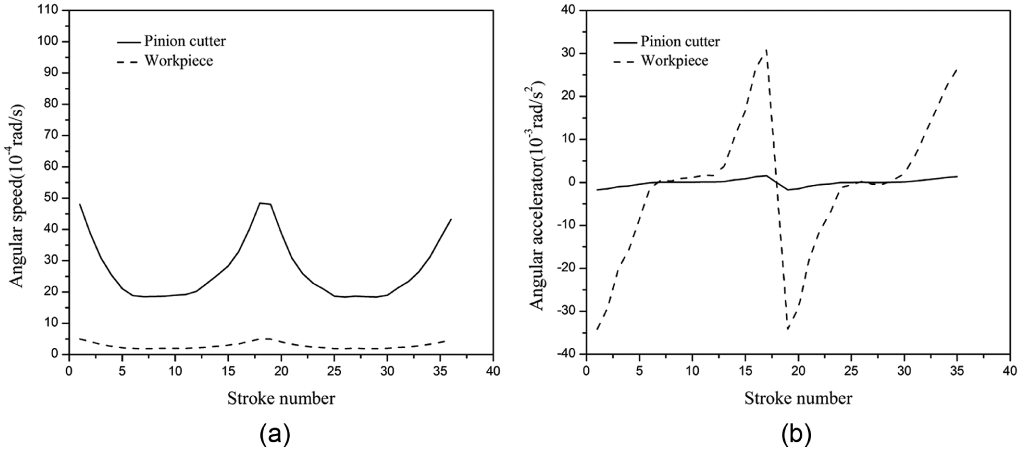
(a) Angular speed and (b) angular accelerator of the pinion cutter and the gear workpiece for efficient gear shaping of the second radial feed.
VERICUT simulation
In order to verify the algorithms and the results in section “Theoretical modeling,” the gear shaping process is simulated using VERICUT code for CNC machining. 25 The simulation model for gear shaping is shown in Figure 13. The geometries of the pinion cutter and the gear workpiece are constructed in the simulation model according to Table 1 and the calculated tooth profile in section “Theoretical modeling.” The stroke speed of the pinion cutter spindle and the angular speed of the pinion cutter and the gear workpiece in each radial feed from Table 1 and section “Theoretical modeling” are set as CNC codes in the simulation.
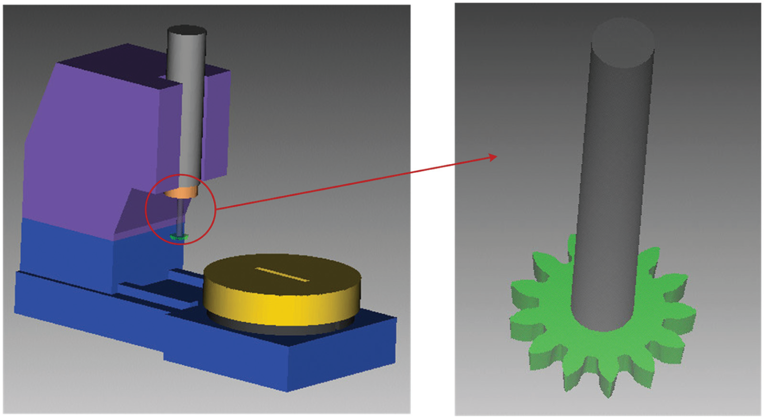
Gear shaping model in VERICUT.
Figure 14 shows the simulated geometric results of the conventional and the efficient gear shaping with the first and second radial feeds. Figure 15 presents a comparison between the generated tooth profiles using the conventional and the efficient gear shaping. Figures 16 and 17 show the theoretically calculated and the simulated cutting areas of the conventional and the efficient gear shaping of the first radial feed, respectively.
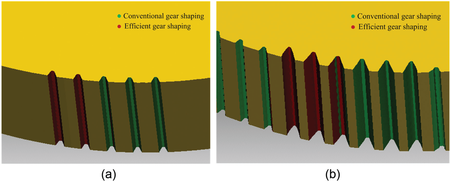
Geometric simulation of gear shaping via VERICUT: (a) first radial feed and (b) second radial feed.
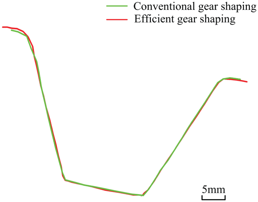
Comparison between the teeth profiles generated by conventional and efficient gear shaping.
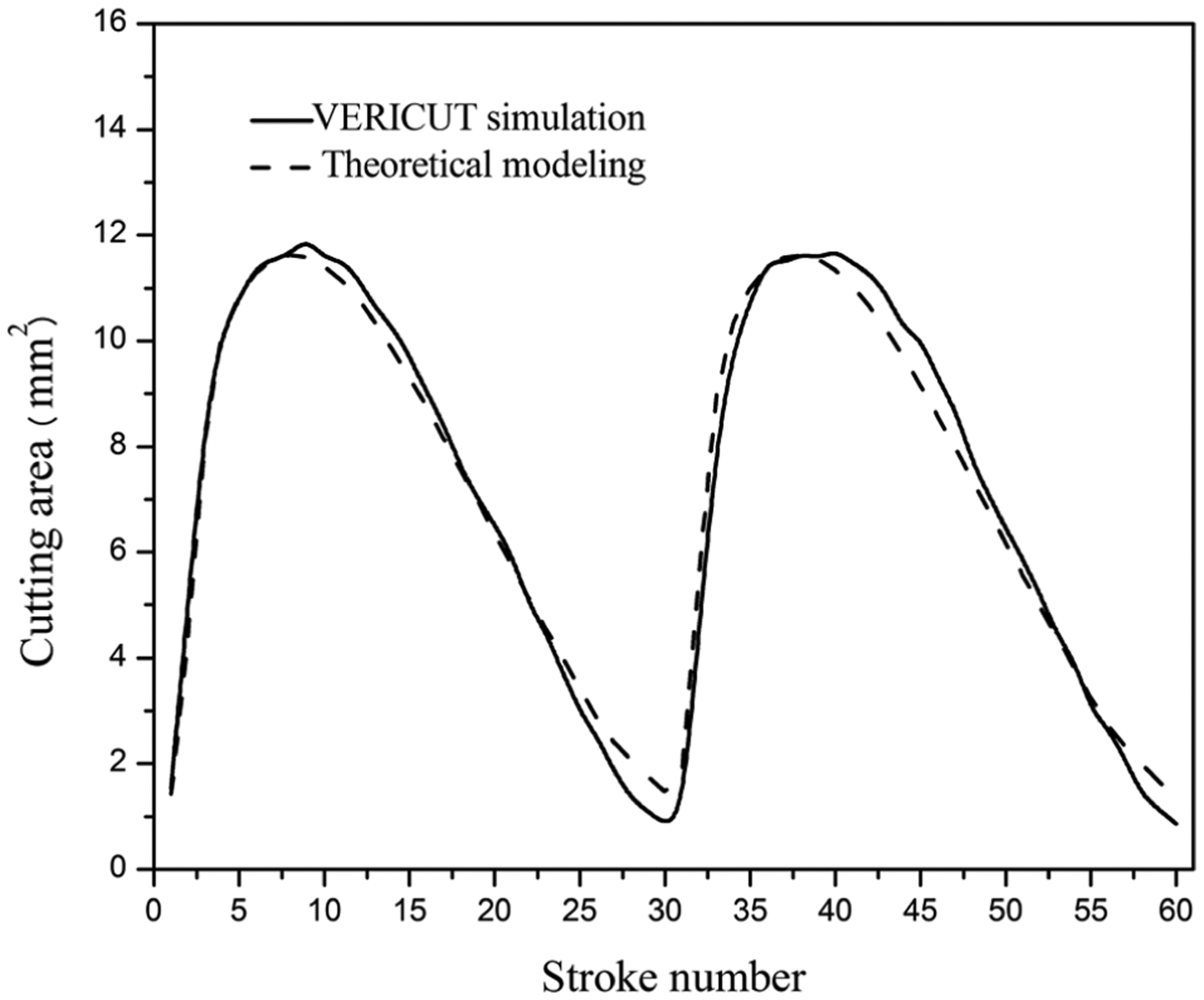
Comparison of the theoretically calculated and simulated cutting areas of conventional gear shaping of the first radial feed.
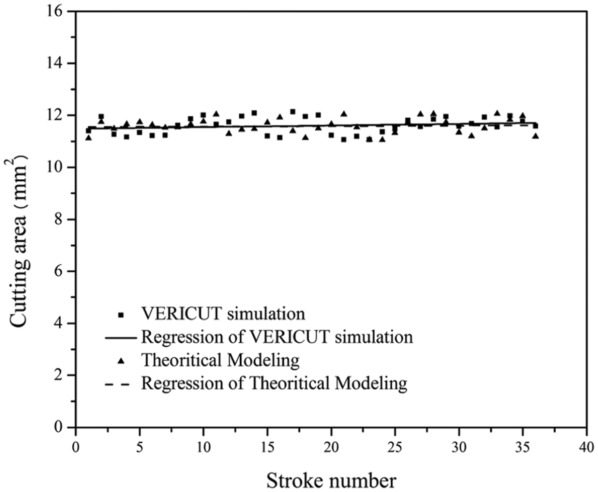
Comparison of theoretically calculated and simulated cutting areas of efficient gear shaping of the first radial feed.
Discussion
From Figures 15–17, it is found that the VERICUT simulated tooth profiles of the conventional and the efficient gear shaping are the same, and the theoretically calculated cutting area fit well to that via VERICUT simulation. Hence, the algorithms for cutting area calculation, analysis, and homogenization are correct and applicable.
As shown in Figures 9 and 10, the number of strokes of the first and second radial feeds in the two machining cycles is reduced by 24 and 23 via the efficient gear shaping, respectively, as compared to 60 strokes of the conventional gear shaping. It means that the process efficiency can be improved up to 40% and 38.3%, respectively. This is much significant to large or heavy gear shapers that are not appropriate to high-speed gear shaping because of their high inertia.
The proposed method is aimed to improve the process efficiency of gear shaping by homogenizing the cutting area of every stroke through optimizing the circular feed rate. The method can significantly enhance the process efficiency of gear shaping, but it will increase the chord length on the tooth profile generated by the shaping strokes whose circular feed rate is greater than that of the conventional gear shaping. Considering such an effect, the efficient gear shaping method is primarily applicable to rough cutting of gears.
As shown in Figures 11 and 12, the circular feed rate of the efficient gear shaping is variational and even changes sharply from acceleration to deceleration. This will cause impact and overload to the driving systems and vibration of the gear shaper. Thus, the circular feed rates should be further revised by considering the dynamics and power of the gear shaper.
Although the target value for cutting area homogenization is set to the maximum cutting area of each radial feed in the current work, the target cutting area should be identical in all radial feeds for a given gear workpiece in practical application. The target cutting area will be determined by the rated load of the gear shaper and the unit cutting force of the gear workpiece. Furthermore, the number of radial feeds and the rate of each radial feed are also needed to be optimized for efficiency and quality.
As an alternative application, the proposed method can also be used for finish cutting of high-precision gears, which is similar to the constant MRR process proposed in Nguyen et al. 26 to compensate the MRR variation–induced machining error. In this case, the target cutting area should be determined according to the quality requirement of the tooth surface and the related allowable elastic deformation of the workpiece-cutter-fixture-shaper process system. Homogenized cutting area corresponds to identical cutting force which will result in uniform elastic deformation of the process system in all shaping strokes. This enables the shaping of high-precision gears.
Conclusion
A new efficient gear shaping method is proposed for rough cutting of involute spur gears. The method improves the process efficiency of gear shaping by optimizing the circular feed rate from constant to variational via homogenizing the cutting area of every shaping stroke to a target value and overcomes the drawbacks of the gear shaping method by controlling radial feed rate.
VERICUT simulation validates the correctness of the new efficient gear shaping method with a case study of gear shaping.
The case study shows that the process efficiency can be improved up to 40% via the efficient gear shaping because of the reduced number of shaping strokes. The method can significantly improve the process efficiency in rough cutting and be applicable to CNC gear shapers without any additional hardware change.
In the future work, dynamics modification of the circular feed rates will be carried out to eliminate impact and overload of the driving systems, and the optimization of the number of radial feeds and the rate of each radial feed is also necessary to improve the process efficiency and quality.
Footnotes
Appendix 1
Declaration of conflicting interests
The author(s) declared no potential conflicts of interest with respect to the research, authorship, and/or publication of this article.
Funding
This work was financially supported by the National Natural Science Foundation of China under grant no. 51275347, the Science and Technology R&D Program of Tianjin under grant no. 13JCZDJC35000, and the National Key S&T Special Projects of China on CNC machine tools and fundamental manufacturing equipment under grant nos 2010ZX04001-191 and 2011ZX04002-032.