
Abstract
The ball end milling process is commonly used for generating complex three-dimensional sculptured surfaces with definite curvature. In such cases, variation of surface properties along with the machined surface is not well understood. Therefore, this article investigates the effect of machining parameters on the quality of surface in ball end milling of thin-shaped cantilever of Inconel 718. A distinct variation is also observed in the measured values of deflection of workpiece: surface roughness and surface damage in different regions, that is, fixed end, mid portion and free end of machined surface. The experiments were conducted according to the central composite design with four factors, namely, cutting speed, feed, workpiece thickness and workpiece inclination with tool path orientation. It is observed that the process parameters have statistically significant effect on machined surface of Inconel 718. Horizontal tool path condition during milling is most favourable in all aspects of surface quality with high speed and lower feed. The surface roughness values at the fixed end of plate are less as compared with that of mid portion and free end sides. Scanning electron microscope images show various defects such as side flow, smeared layer, microparticle, grooves and feed marks.
Introduction
The ball end milling of thin-walled components is a widely used machining operation to generate three-dimensional complex profiles in aircraft industries. The superalloys are mostly used in the aerospace applications due to their ability to maintain excellent mechanical strength at elevated temperatures. Inconel 718 is one of the most commonly used superalloy in this class; in particular, it finds applications in aero-engines to manufacture flexible web parts such as discs, blades, sheets and rings.1–3 However, machining of this material is still a difficult task due to its high specific strength and poor thermal properties, which give rise to higher tool wear and poor machined surface integrity. The machining process using a ball end mill, however, is very complex because of its intermittent nature of the operation and continuous variation of chip dimensions during machining.4,5
A number of researchers have worked on the experimental as well as mathematical modelling of ball end milling. There are attempts to identify optimum processing parameters that give the best surface finish. Moreover, most of these studies are related to generation of plane surfaces using radial feed in a ball end milling. Lee et al. 6 demonstrated the effect of workpiece inclination of 0°, 15° and 45° with different cutter orientations in a ball end milling operation. The minimum workpiece deflection and the better surface finish were observed at the workpiece tilt angle of 45° with vertical outward cutter orientation. Zhu et al. 7 developed a mechanistic model for prediction of forces in ball end milling. This model specifies tool path and workpiece surface geometry to determine the relative position in the workpiece coordinate system and cutting point trajectory. Sharman et al. 8 observed that a good surface finish can be obtained in high-speed ball nose end milling on 45° inclined surface on Inconel 718 plate. Furthermore, the experimental analysis on cutter orientation and lead or tilt angles during five-axis ball end milling of turbine blade has shown that the best surface finish is obtained in horizontal inward direction with a 15° tilt angle with respect to vertical axis. Sonawane and Joshi 9 developed analytical model that evaluates the undeformed and the deformed chip dimensions including chip length, width and thickness. The undeformed and deformed chip dimensions are functions of cutter rotation angle, instantaneous cutter radius, helix angle and other processing parameters. Bouzakis et al. 10 evaluated the undeformed chip geometry and cutting forces using initial part geometry, tool path and tool geometry as input parameters. Furthermore, they have shown that the chip width and thickness of the cutting edge at its successive revolving positions are a function of two cutting edges of a ball end mill tool in the case of down milling. Antoniadis et al. 11 developed a simulation model to quantitatively determine the topography of the surface produced and the resulting surface roughness. Berra et al. 12 concluded that the cutting tool deflection has pronounced effect on the surface error than the workpiece deflection during machining of different parts. This is contrary to open-ended cantilever-type geometries, where the component of workpiece deflection is remarkably higher. Mizugaki et al. 13 presented a theoretical estimation of machined surface profile. They have predicted cusp height at any point on a machined surface using their model. Arizmendi et al. 14 modelled the surface topography of ball end milled surfaces accounting for tool parallel axis offset. In their model, the equations of cutting edge trajectories and the envelope above the material swept by the tool have been derived. As per the effect of machining environment is concerned, Shokrani et al. 15 observed that cryogenic cooling has a significant potential to improve surface finish of the machined parts as compared to dry machining without a noticeable increase in power consumption. Mansour and Abdalla 16 show that an increase in either feed or axial depth of cut increases the surface roughness, while an increase in the cutting speed decreases the surface roughness. Dosbaeva et al. 17 investigated the origin of defect formation by examining surface morphology as well as cross sections of the machined surfaces.
Thus, it appears from the past literature that majority of the authors focussed their attention on mechanics of cutting forces and chip formation using experimental and numerical modelling techniques in ball end milling of superalloys. Hardly any study experimentally analysed the surface quality after machining as a function of machining conditions in ball end milling of Inconel 718. None of the studies analysed the effect of part flexibility on the surface integrity during ball end milling. Therefore, it appears that the research on surface generation and the subsequent surface integrity after machining is not elaborated as required. In view of the above, this work, therefore, extends the laid in the literature further to analyse the machined surface integrity in terms of surface roughness and surface damage.
Experimental work
Experimental theme and design
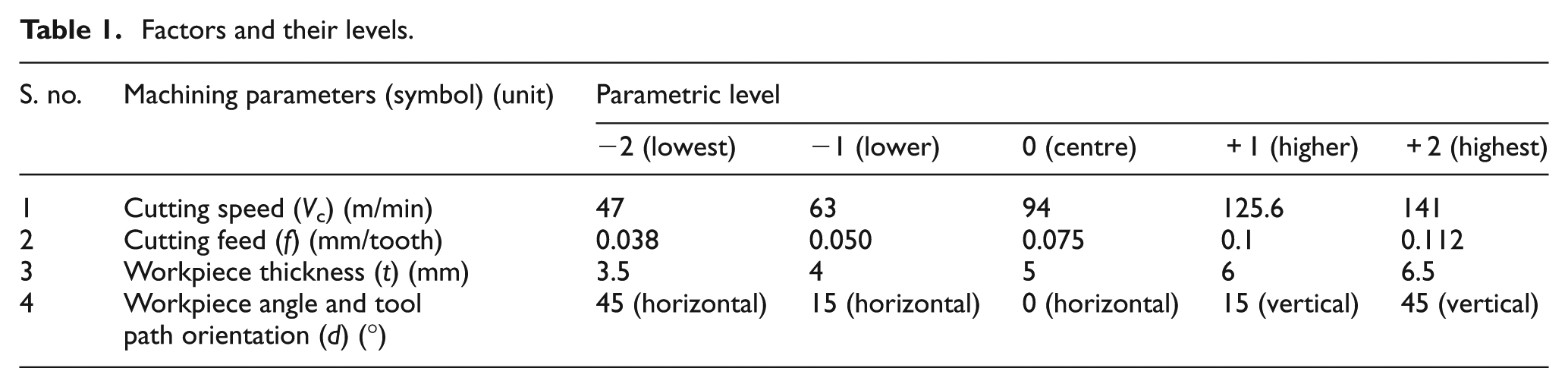
In line with the objectives of the work, the selected response variables are surface roughness, deflection of workpiece and surface damages after ball end milling. The range of cutting conditions for this work was selected based on the preliminary experiments, literature findings and the tool manufacturer’s catalogue, 18 shown in Table 1. In this experimental research, central composite design (CCD) matrix was chosen based on the number of factors and their levels. 19 In this case, four control factors, each at five levels, were chosen.
Factors and their levels.
Workpiece preparation and experimental set-up
The experiments were carried out on rectangular Inconel 718 specimens of dimensions 75 mm × 25 mm long with different thicknesses 3.5, 4, 5, 6 and 6.5 mm. All specimens were heat treated before machining to normalize the residual stresses generated while producing Inconel 718 cantilevers for a better analysis of the surface and subsurface qualities. They were solutionized at 954 °C–982 °C for 1 h and air cooled. Furthermore, the solutionized samples were aged at 718 °C for 8 h and air cooled. The chemical composition of Inconel 718 is 51.3% Ni, 20.14% Fe, 18.17% Cr, 4.8% Nb, 3.25% Mo, and balance C. Solid carbide Ti-Al-N-coated ball end mill cutters of 10 mm diameter, 10° rake angle and 30° helix angle with two cutting flutes were used for the experiments. A vertical computer numerical control (CNC) milling machine (TM2; HAAS) was used to carry out the experiments in dry environments. The slots were machined at a constant depth of cut of 1 mm during each experimental run. The ball end milling was performed on inclined cantilever-shaped workpiece along two paths, horizontal outward and vertical upward, and at 45° and 15° workpiece inclination angles. In addition, tests were also performed on the flat horizontal (0°) workpiece to compare the results (Figure 1(c)–(e)). The optimum parametric settings have been achieved to minimize the surface roughness and workpiece deflection using response surface methodology (RSM) in the framework of CCD. The experiments were performed at various machining conditions as per the CCD matrix, 19 as shown in Table 2. Each experiment was replicated once. Each experiment is performed using a new ball end mill. Thus, a total of 60 tools were used, including tool edge photograph after milling (Figure 2). A deflection sensor was attached at the free end of the cantilever work specimen. It was connected to a deflection measuring (acquisition) software through an amplifier. After machining, each work specimen was cut into three segments across the machined surface of the size 15 mm × 10 mm, using a precision saw for measurement of the surface roughness and surface damages. Surface roughness of the machined surface was measured using a portable surface roughness tester (Surftest SJ 301; Mitutoyo). The cutoff length and the evaluation length selected were 0.8 and 4.0 mm, respectively. However, the entire slot of 45 mm was measured for surface roughness.
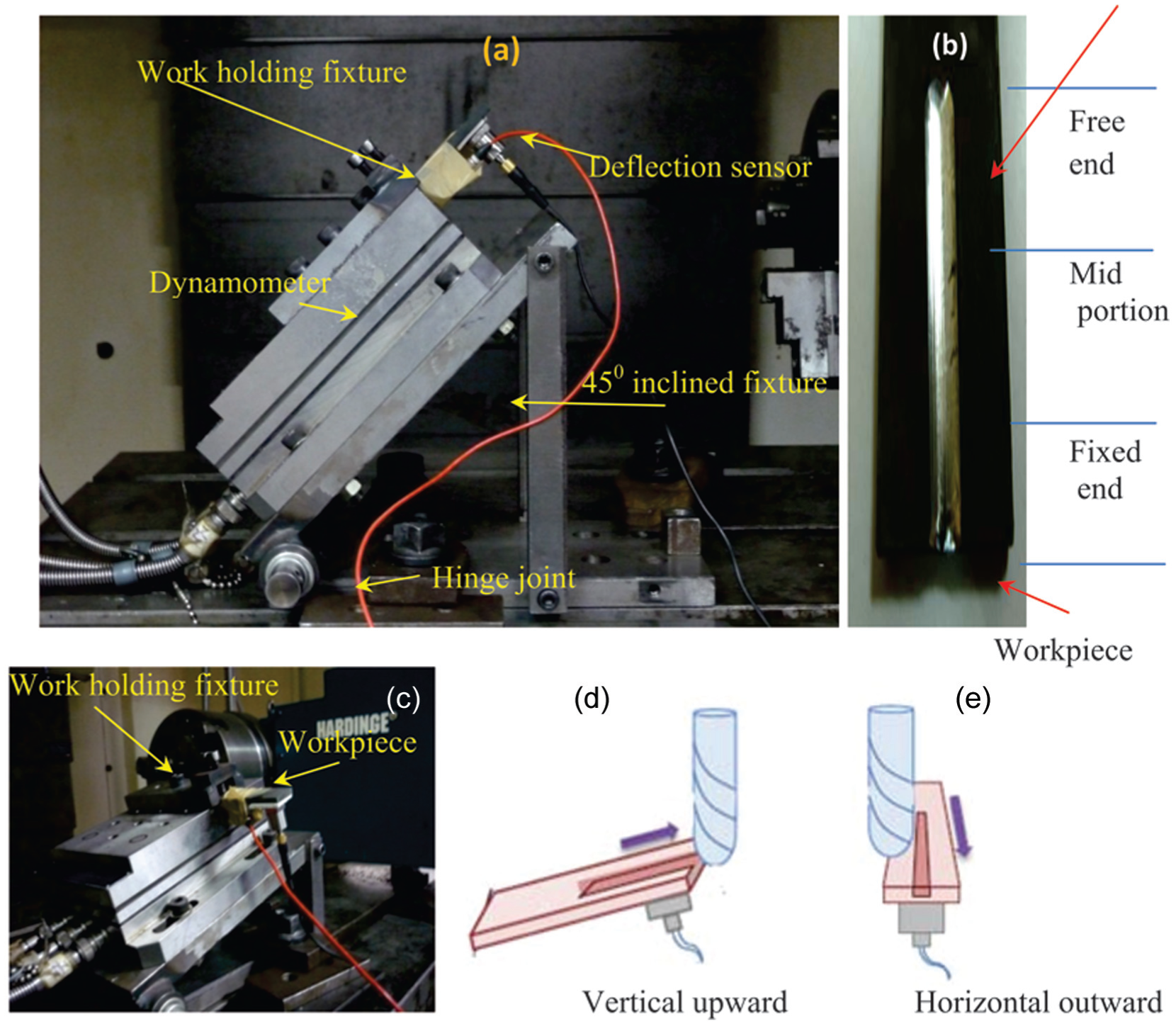
(a) Close-up view of experimental set-up, (b) machined workpiece and (c) details of workpiece position with (d) vertical and (e) horizontal cutting tool path directions.
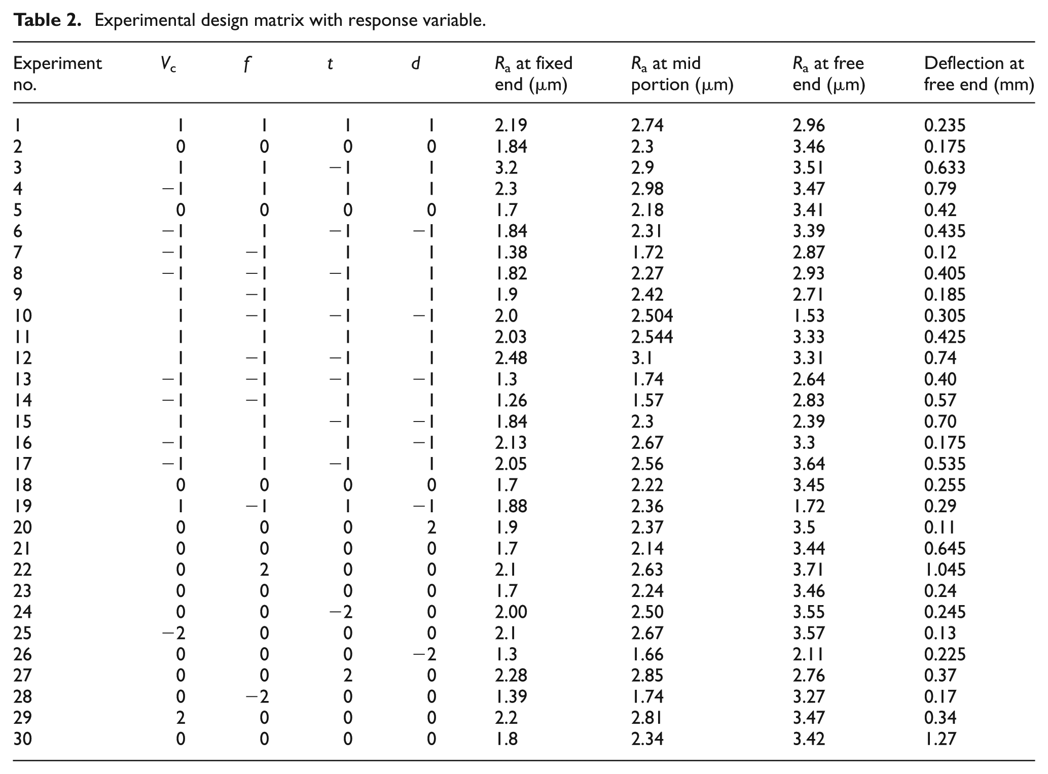
Experimental design matrix with response variable.
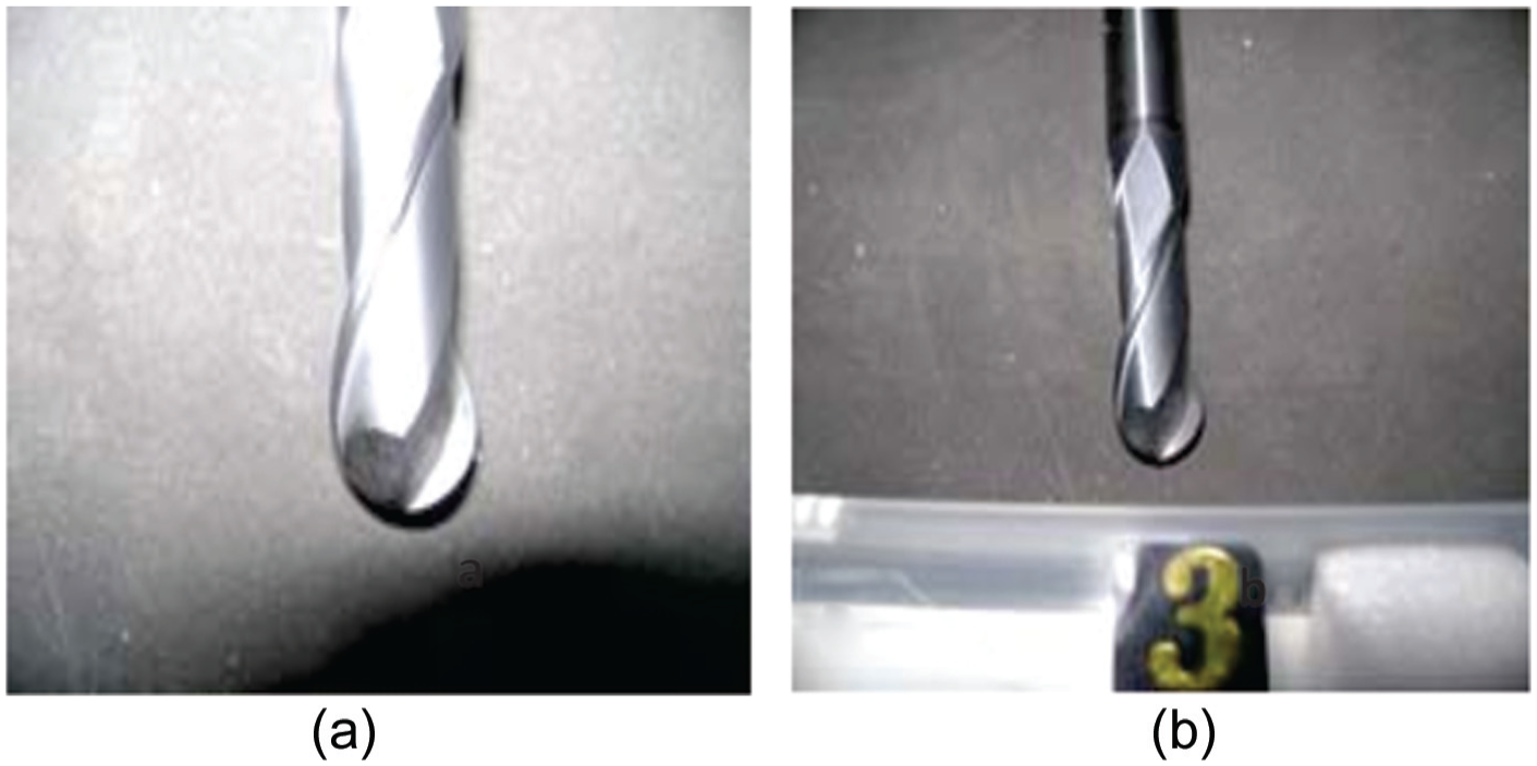
Ball end mill cutter (a) before use and (b) after use for experiment no. 3.
Results and discussion
Experimental results were analysed in terms of understanding of the workpiece deflection, surface roughness and surface damage at fixed end, mid portion and free end of the machined surface.
Analysis of workpiece deflection
In ball end milling, forces are generated due to shearing and frictional resistance in the work–tool interface region. In case of thin-shaped cantilever workpiece, these forces are likely to cause deflection. The concept of analytical model has been considered for determining the instantaneous workpiece deflection as the ball end mill cutter passes from fixed end to free end of the cantilever (see Figure 3). This model equation is applicable for beam which is uniform, rectangular, inextensible and made of a non-linear material. The Euler–Bernoulli model equation as given in equation (1) has been used to evaluate the cantilever beam deflection at any point in between fixed end and the position of load acting on the cantilever surface. The Euler–Bernoulli equation describes the relationship between the beam deflection and the applied load as given below 20
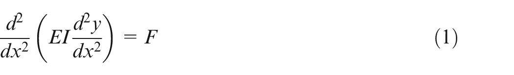
where E = modulus of elasticity (GPa), I = moment of inertia of cantilever beam (mm4), x = instantaneous distance of deflection (mm) and y = deflection at x (mm).
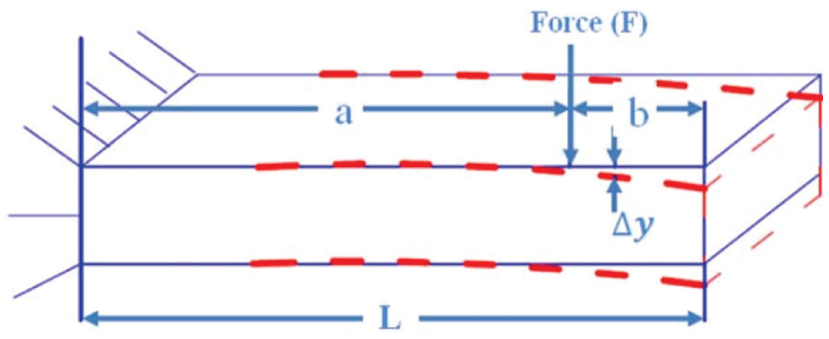
Deflection of cantilever beam.
In equation (1), the curve y (x) describes the deflection y of the beam at some position x and F is a force per unit length. Therefore, equation (1) is modified to evaluate the instantaneous deflection at any point x along the length of cantilever
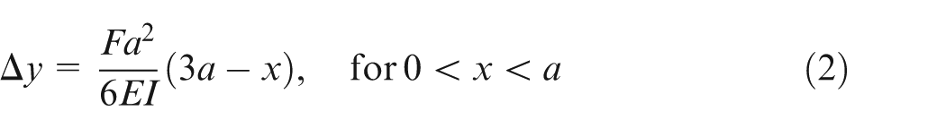
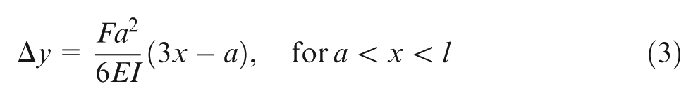
where a = distance measured from fixed end side to point of application of force (mm) and l = length of cantilever. This analytical method of finding out deflection is applicable for static force only.
Parameter significance using analysis of variance
The milling process parameters which show significant contribution in producing deflection of cantilever plate are determined using analysis of variance (ANOVA). It is observed that the control factors such as cutting speed, feed, workpiece thickness, workpiece angle and tool path, and interaction between cutting speed and feed, workpiece thickness, and workpiece inclination and tool path orientation significantly influence at 95% statistical confidence interval (Table 3). As the p value of these factors is less than 0.05, they are considered statistically significant.
ANOVA for deflection of thin-shaped cantilever plate of Inconel 718.
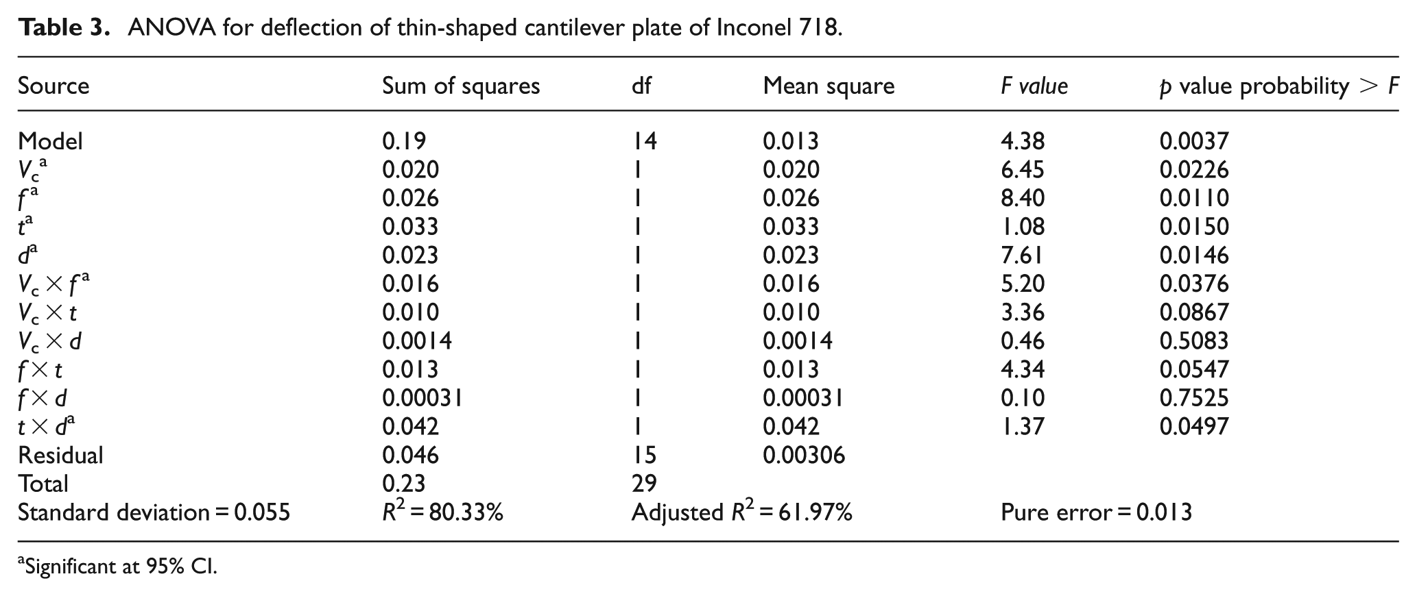
Significant at 95% CI.
Parameter effect analysis
The main effect plots show that the deflection of the cantilever plate is 0.431 mm at 47 m/min, and the value increases to 0.701 mm when the cutting speed increases to 141 m/min (Figure 3(a)). As the cutting speed increases, the material removal rate also increases. Thus, larger magnitude of cutting forces is experienced during machining. Hence, a significant increase in the workpiece deflection is observed at higher cutting speed.
The main effect plots in Figure 4(b) show that the deflection of the cantilever plate increases with the increase in feed. When the feed increases, the magnitude of deflection also increases gradually. The feed is found to be the most significant factor on deflection, and when the feed increases from f1 to f2, deflection also increases from δ1 to δ2. The rise in the feed causes increase in the deflection because of increase in the cutting cross-sectional area. This causes an increase in the resultant forces, which tries to push cantilever to downward direction, as shown in Figure 5. 10
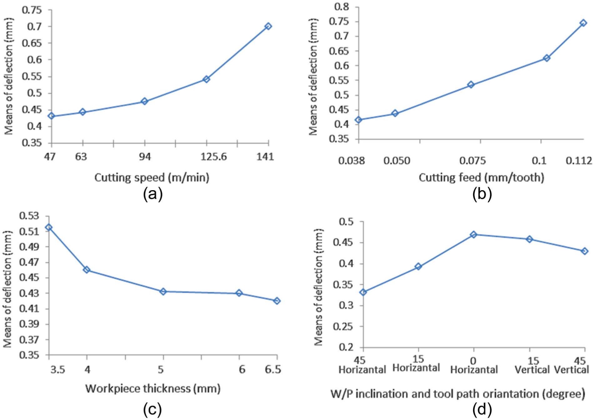
(a–d) Main effect plots of deflection of thin-shaped cantilever beam.
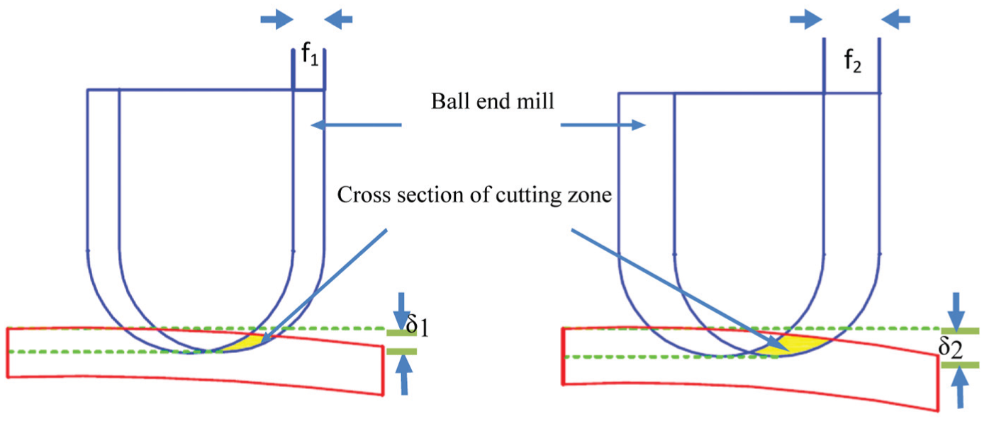
Effect of feed on deflection on thin Inconel 718 plate (δ1 and δ2 are the deflections of thin-shaped cantilever beam).
It is found that the minimum deflection occurs when the plate thickness increases. An increase in the plate thickness causes an increase in the rigidity of the workpiece, which in turn increases the moment of inertia and thereby facilitates smooth machining with less deflection (Figure 4(c)).
A higher deflection is observed at horizontal workpiece inclination of 0° at horizontal outward cutter orientation (see Figure 4(d)). It is because of a higher chip load per tooth and thereby increasing thrust experienced by the cutter. However, a minimum deflection is observed at 45° workpiece inclination with horizontally outward cutter orientation due to comparatively lower chip load per tooth which is generated while machining. 21
The effect of interaction between cutting speed and feed on deflection is presented using a surface plot shown in Figure 6. The surface plot shows that the deflection is observed low at lower cutting feed (0.038 mm/tooth) and lower cutting speed (63 m/min). However, with an increase in the feed to 0.112 mm/tooth with higher cutting speed, the maximum deflection of workpiece of 0.74 mm is observed. The feed has more dominant effect on the workpiece deflection than that of the cutting speed. An increase in the feed results in an increase in chip load and thereby increases the overall thrust force during machining at the free end of cantilever causing higher deflection. 9
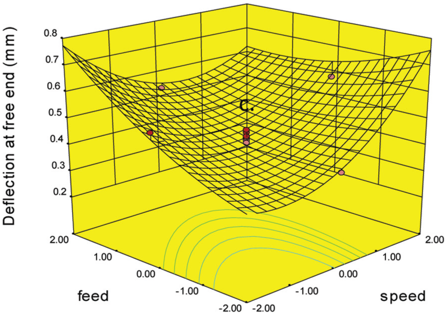
Surface plot showing the effect of cutting speed and feed on deflection at free end.
The effect of interaction between workpiece thickness and workpiece inclination and tool path orientation on deflection is presented using a surface plot in Figure 7. The minimum deflection is observed at 45 degree workpiece inclination with horizontal outward tool path orientation and 6.5 mm thick workpiece. However, higher workpiece deflection is observed at 0 degree workpiece inclination with horizontal out ward tool path orientation and 3.5 mm thick workpiece. Due to the lower thickness of workpiece, the rigidity of workpiece decreases and deflection increases.
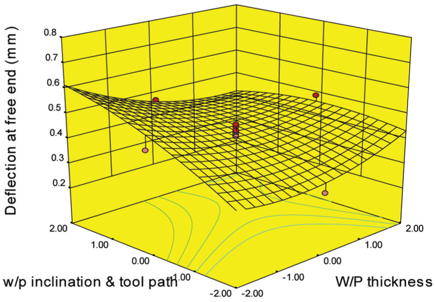
Surface plot showing the effect of workpiece thickness and workpiece inclination and tool path orientation on deflection at free end.
Analysis of surface roughness
The surface roughness of the cantilever-shaped thin plate after machining is measured at different locations: fixed end, mid portion and free end.
Surface roughness assessment on machined part (fixed end, mid portion and free end)
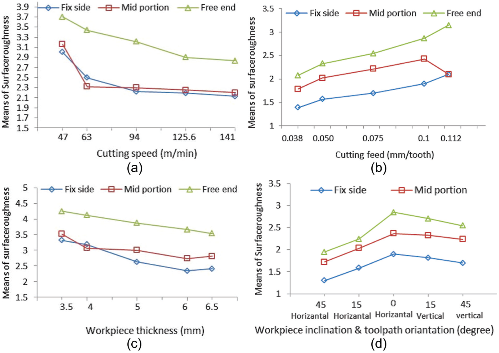
The effect of variation in machining conditions on the surface roughness at different locations on the workpiece is presented in Figure 8. It is understood that the mechanics of ball end milling of cantilever workpiece has a significant influence on the machined surface roughness (Ra) in various cutting zones. The plot shows three different values of surface roughness: Ra at fixed end, Ra at mid portion and Ra at free end of the workpiece. It is observed that the values of surface roughness at the fixed end are relatively lower than at the mid portion and free end. It is further noted that the surface roughness of the machined cantilever-type workpiece is higher at the free end part of the workpiece followed by the reduced surface roughness at the fixed end and mid part of the workpiece.
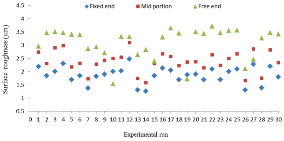
Comparison of surface roughness at various machining conditions at fixed end, mid portion and free end of the workpiece.
Statistical analysis of surface roughness
In case of surface roughness, the cutting speed, feed, plate thickness and interactions between cutting speed and feed, cutting speed and workpiece thickness, speed and workpiece inclination and tool path orientation, feed and workpiece thickness, feed and workpiece inclination and tool path orientation and workpiece thickness and workpiece inclination with tool path have significant influence at 95% statistical confidence level (Table 4). The summarized ANOVA of surface roughness is presented in Table 5. It is observed that the surface roughness at free end is most significantly influenced by input machining parameters. This can be attributed to the maximum deflection of workpiece and the tool contact with the workpiece prevailing during machining. As the ball end mill cutter moves from the fixed end to free end of the workpiece, the width and depth of cut are reduced. It causes deflection, vibrations and chatter that lead to an increase in the surface roughness. 10 The effect of machining parameters on the roughness of machined surface is described using the main effect plots shown in Figure 9.
ANOVA for surface roughness Ra at fixed end.
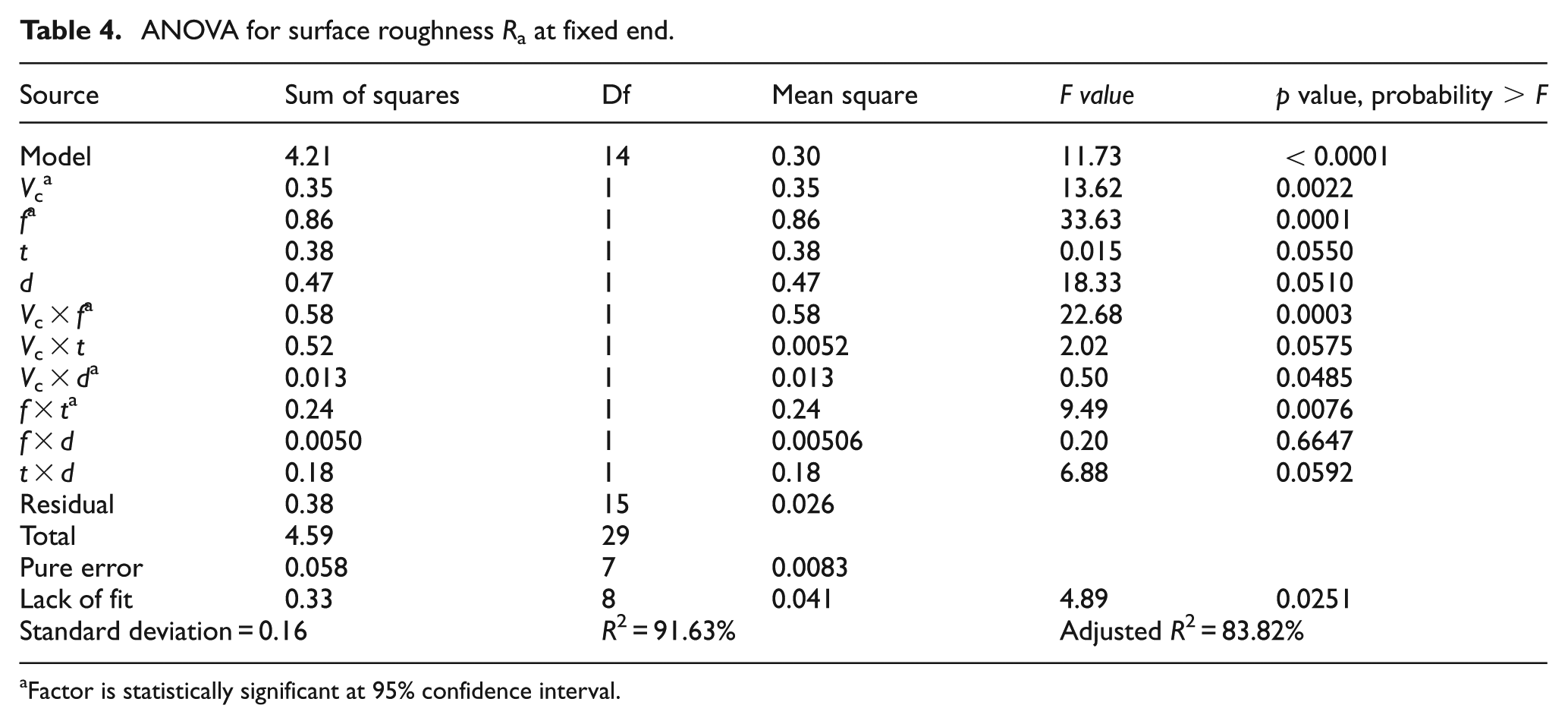
Factor is statistically significant at 95% confidence interval.
Summarized ANOVA for surface roughness Ra.
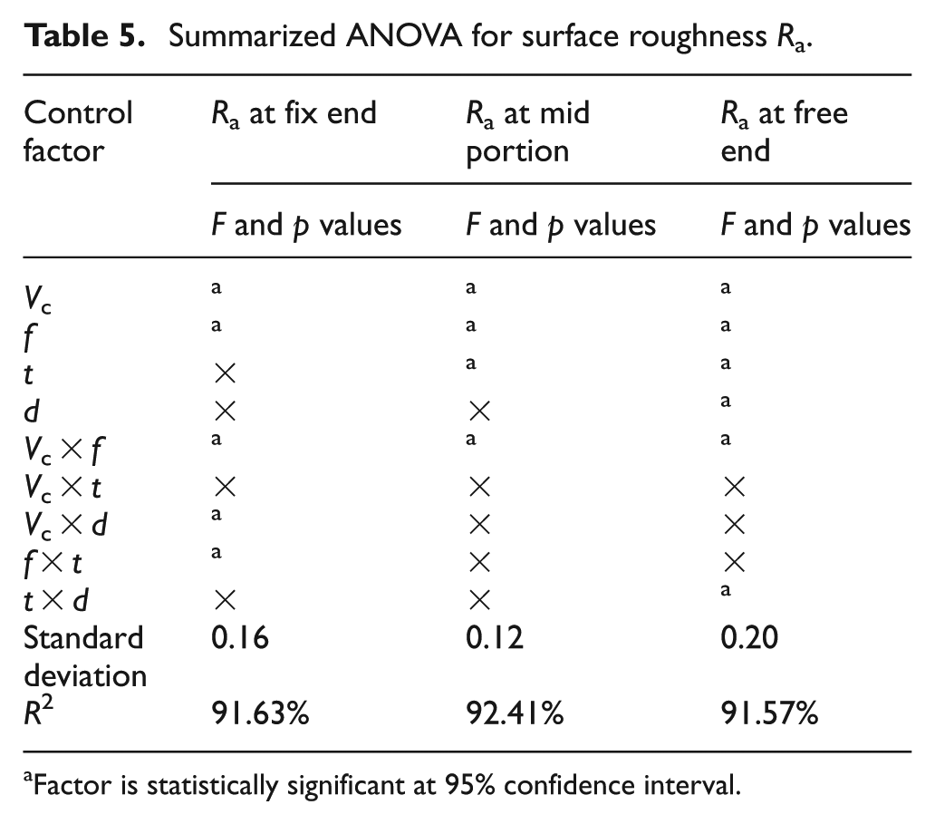
Factor is statistically significant at 95% confidence interval.
(a–d) Main effect plots of surface roughness.
The main effect plots in Figure 9(a) show that as the spindle speed increases, the surface roughness decreases at the fixed end, mid portion and free end of machined surfaces. The cutting speed also shows a statistically significant influence on the surface roughness at these locations. In case of the entire workpiece region, that is, fixed end, mid portion and free end, the surface roughness is higher at 47 m/min and further increases in the speed reduction of Ra values. As compared to the fixed end and mid portion, the values of surface roughness are higher at the free end of the thin machined workpiece. This can be attributed to the increased deflection of the machined workpiece leading to higher chatter effect.
In the case of influence of feed on surface roughness (Figure 9(b)), it is observed that as the feed increases from 0.038 mm/tooth/rev to 0.112 mm/tooth/rev, the surface roughness at fixed end, mid portion and free end of the machined workpiece also increases. At the feed of 0.112 mm/tooth/rev, the highest mean surface roughness (Ra) of 3.15 µm was recorded on the free end side of the machined workpiece. However, the lowest surface roughness of 1.39 µm was noted at the fixed end of the machined workpiece at the feed of 0.038 mm/tooth/rev (Figure 9(b)). In the case of effect of feed on the surface roughness, the free end shows higher Ra value. The increasing trend is seen for all the locations of the workpiece with the feed rate. An increase in the feed rate results in an increase in a chip load and thereby increases the overall thrust force during machining at the free end of cantilever. Similar results were presented by Sonawane and Joshi. 9
It is found that the plate thickness has significant influence on the surface roughness at fixed end, mid portion and free end side of the machined plate. The minimum surface roughness of 2.41 µm Ra is observed at the fixed end of 6.5-mm-thick workpiece plate, and maximum surface roughness of 4.25 µm is observed at the free end of plate for the 3.5-mm-thick plate. Furthermore, the increase in rigidity of thick plate produces less deflection and vibration at the fixed end and middle portion of the plate, and hence, there portions show lower surface roughness (Figure 9(c)).
It is observed that the tool path does not have a significant influence on the surface roughness at fixed end and mid portion of the workpiece. Minimum surface roughness of 1.3 µm Ra at the fixed end of plate is observed when the workpiece is 45° inclined and cutter is in horizontally outward direction. However, the maximum surface roughness of 2.85 µm Ra is observed at the free end side when the workpiece is at 45° inclined position and the cutter moves in vertically upward directions with respect to the machined workpiece (Figure 9(d)). Furthermore, it is noted that in milling with 0° inclination with horizontal outward tool path orientation, the forces and deflections are higher as compared with the inclined workpiece and both tool path orientations. This resulted in higher chip load per tooth and thereby increases the thrust experienced by the tool. However, a comparatively lower chip load is observed during inclined workpiece with both tool path orientations showing with minimum surface roughness values on the machined workpiece (Figure 10(a)–(c)).
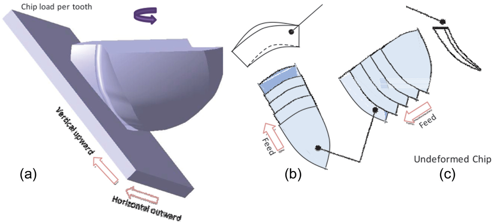
(a) Cutting edge–workpiece interaction at inclined workpiece and chip load (b) at vertical upward and (c) at horizontal outward cutter orientations.
The effect of workpiece angle on the surface roughness is shown in Figure 9(d). It appears to be more prominent at the mid portion of the machined workpiece. However, a large deflection at the free end side of the machined workpiece leads to a higher value of surface roughness. It can be seen from Figure 11 that as the deflection occurs instantaneously, the workpiece angle also changes from
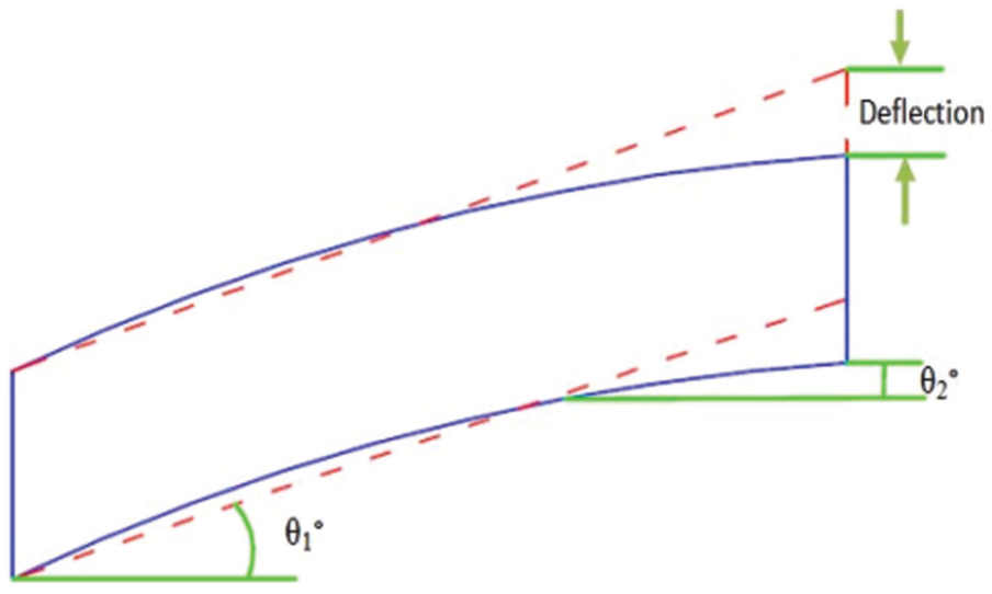
Change in workpiece angle due to deflection.
The effect of interaction between cutting speed and feed on surface roughness is presented using a surface plot in Figure 12(a)–(c). It is observed that the interaction of cutting speed and feed has a significant impact on surface roughness at fixed end, mid portion and free end of the workpiece. At 0.038 mm/tooth/rev of feed and 47 m/min cutting speed, surface roughness is less than 1.2 µm, and for a 141 m/min cutting speed and with an increase in the feed to 0.112 mm/tooth/rev, the surface roughness is greater than 3.0 µm. Figure 12(a) shows that the feed has more dominant effect on the workpiece surface roughness than that of the cutting speed.
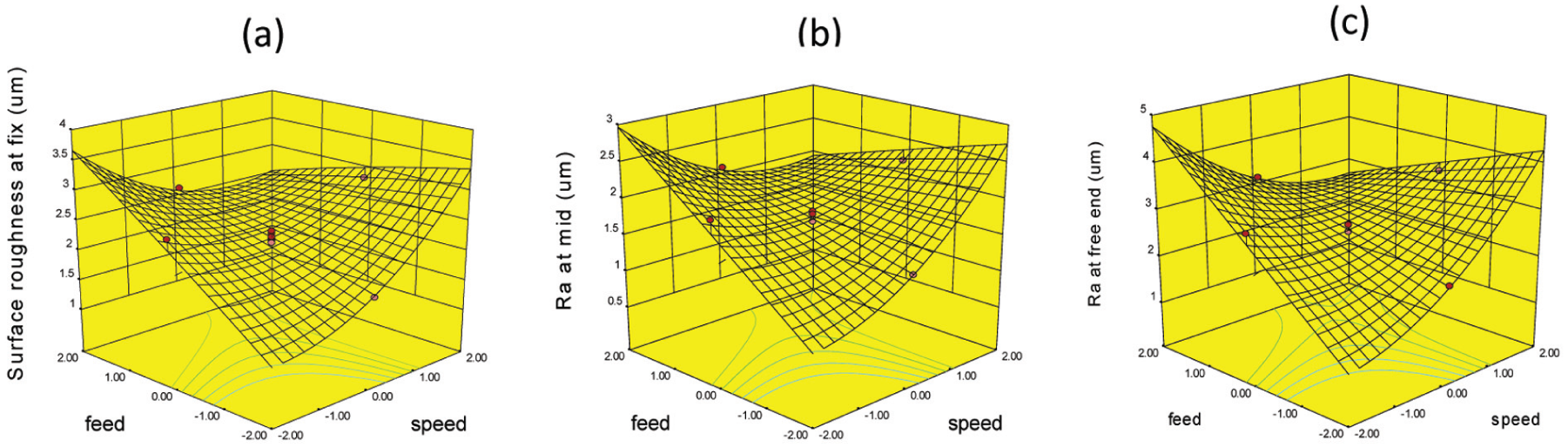
Response surface plot of speed and feed for Ra at (a) fixed end, (b) mid portion and (c) free end.
The effect of speed and workpiece inclination with tool path orientation is significant at fixed end of cantilever (Figure 13). The minimum surface roughness is observed at 45° inclined workpiece and at horizontal outward cutter orientation at 94 m/min cutting speed. However, the maximum surface roughness was observed at 0° inclined horizontal workpiece and horizontal outward cutter orientation with minimum cutting speed. It is because of the maximum chip load on the horizontal outward direction with 0° inclination of workpiece.
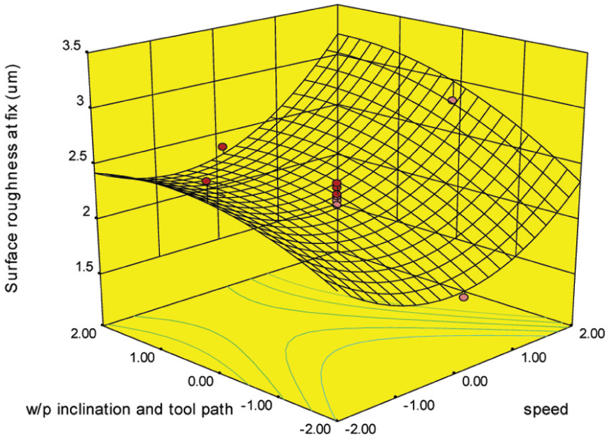
Response surface plot of speed and workpiece inclination and tool path orientation for Ra at fixed end.
It is observed that the interaction of workpiece thickness and feed has a significant impact on surface roughness of workpiece at fixed end (Figure 14). The minimum surface roughness of 1.73 µm was observed at higher workpiece thickness and minimum values of feed rate of cantilever-shaped workpiece. However, the highest surface roughness greater than 3.4 µm was observed on thinner as well as thicker workpiece with higher feed. This is because the workpiece generates a wide rubbing zone on the machined surface at higher magnitude of cutting feed. Both these phenomena led to the higher machined surface roughness at the fixed end of cantilever.
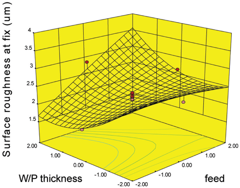
Response surface plot of feed and workpiece thickness for Ra at fixed end.
The minimum surface roughness is observed at 45° inclined workpiece and horizontal outward cutter orientation at 5-mm-thick workpiece (Figure 15). However, the maximum surface roughness was observed at 0° inclined horizontal workpiece and horizontal outward cutter orientation. The maximum chip load is experienced on the horizontal outward direction with thicker workpiece, and hence, the maximum deflection is produced when 0° inclined horizontal workpiece and outward tool path direction are employed. 6
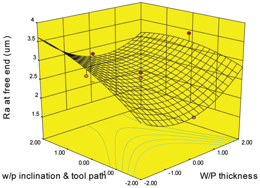
Response surface plot of workpiece thickness and workpiece inclination with tool path orientation for Ra at free end.
Analysis of machined surface topography
Surface topography in ball end milling of thin cantilever beam is being hampered due to deflection of workpiece. It is one of the major characteristics of machined parts for aerospace applications. 22 Scanning electron microscope (SEM) images of the machined surface were captured to reveal the surface irregularities caused due to machining. Even though the surface appears smooth, there may be many surface irregularities which can be noted under high magnification microscopy. In order to reveal these irregularities, the SEM was performed. Feed marks and grooves are formed on the machined surface due to indentation of worn out tool tip into the machined surfaces. These grooves and feed marks are seen throughout the surface across feed direction (Figure 16(d), (e) and (i)). The severe processing conditions during machining cause viscous flow of work material due to high cutting temperature generated in the machining region. 11 As a result, the machined surface shows a side flow of the material parallel to the feed direction (Figure 16(b), (f), (g) and (h)). The microparticles adhered on the machined surfaces seen in Figure 16(a), (f) and (i) are the result of severe friction between the underside of the chip and surface. A smeared layer is formed due to high temperature generation at high spindle speed of 141 m/min in the machining region, which causes thermally enhanced deformation at the near surface layer seen in Figure 16(a). The machined surface is a result of friction and rubbing, and it causes the chip particles to adhere on the machined surface. These patches subsequently get trapped by chip due to difficulty in their evacuation.22,23
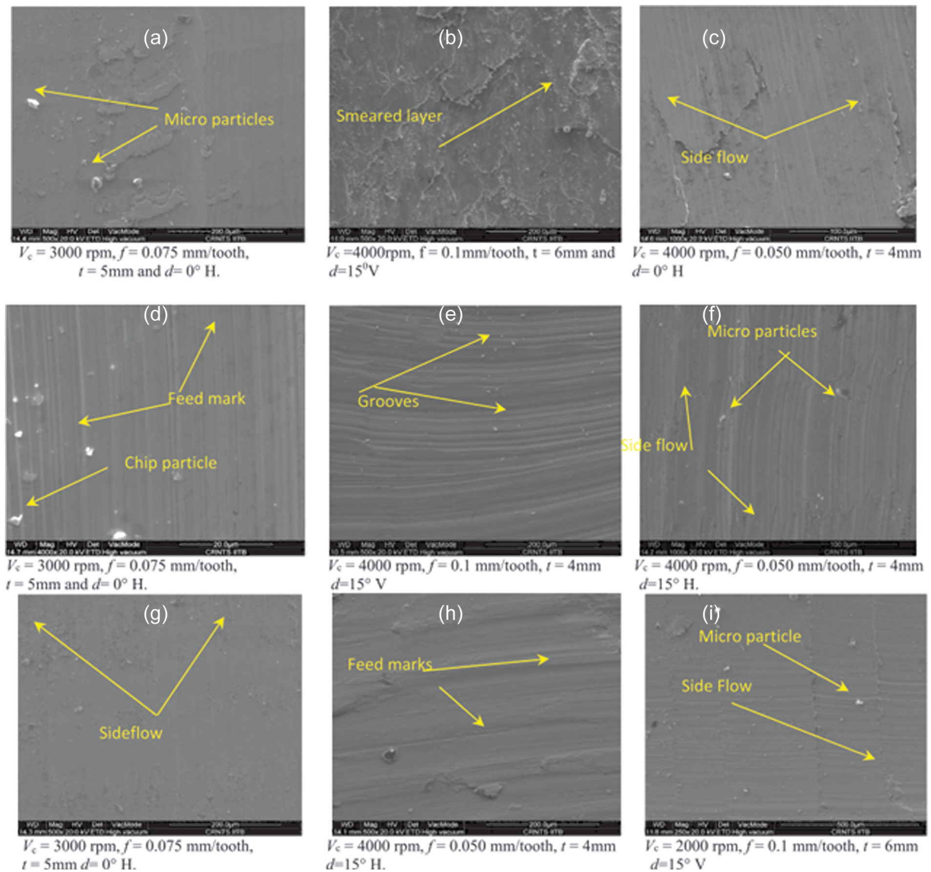
SEM images of defects observed on the surfaces of workpiece at different experimental conditions: (a–c) fixed end, (d–f) mid portion and (g–i) free end of machined surface.
Conclusion
The experiments were carried out to analyse the effects of process parameters on surface integrity of thin cantilevers of Inconel 718 using ball end milling. The following conclusions are drawn:
The lower surface roughness value of 1.26 µm was found at the fixed end, and higher surface roughness value of 3.71 µm was observed at the free end of the cantilever machined surface. Chip load experienced per tooth by the ball end milling cutter governs the deflection of plate. A minimum deflection is observed at 45° workpiece inclination with horizontally outward cutter orientation.
The higher surface roughness was observed at free end of the machined workpiece with higher deflection value of 1.045 mm.
The machined surface and near surface layer alterations are evident. Severe friction between tool cutter and machined surface generates high temperature causing thermally enhanced deformation leading to smeared layer and side flow of the material.
Footnotes
Acknowledgements
The authors gratefully acknowledge the help provided by Nilesh Nikam, during the experimental work. The authors are also grateful towards the guidance and help provided by Sachin Mastud and Sagar Shinde during testing of work specimen. Thanks to MHRD Govt. of India, TEQIP-I for providing the grant for CNC milling machine for the experimental.
Declaration of conflicting interests
The author(s) declared no potential conflicts of interest with respect to the research, authorship and/or publication of this article.
Funding
The author(s) received no financial support for the research, authorship and/or publication of this article.