
Abstract
The dynamic coupling problem for the self-designed “3 parallel ∪ 2 series” mixed-type numerical control machine tool is studied based on the singular constraints and position coupling factors in order to ensure that the machine can have better dynamic characteristics and a higher quality of parts during the process of machining complex surface. This article puts forward a method based on singular constraints and the coupling factor. A whole dynamic coupling model of series and parallel mechanism is established and the coupling factors are determined. Numerical and parameter simulations of mechanism are analyzed and the real working space is obtained. And this article takes the simulation of the process of machining complex part and the force of the machine tool. The simulation results show that the established dynamics model is credible and reliable on the basis of considering singular constraints and position coupling factors. It is proved that the simulation data can correspond to the established model and the situation of force and kinematic suits the working mechanism. The cutting experiment of complex surface parts was took and the machine tool was run more smoothly and faster than the conventional machine tools. The velocity of the machine is regular and circular and there are no kinematic singularity data on the machine’s trajectory. The trajectory of the tool is in the working space completely and the accuracy of the part is good. The surface roughness results show that the kinematics accuracy of the machine tool is good. The interference fringe results show that the force of the machine tool is uniform. As there is no singular coupled vibration and collision, it is proved that the theoretical analysis is correct. The dynamics model of 3PTT serial and parallel mechanism is complete in this article. And the working space of the mechanism is obtained on the base of analysis of the singular constraints and position coupling factors. The article has carried out the dynamic simulation and processing experimental verification. Not only the method and process of this article was solved by dynamics coupling problem of 3PTT-2R numerical control machine tool actively, real-time and effectively, but also it was laid a foundation for accurate control of numerical control machine tools.
Introduction
The characteristics of parallel or serial–parallel machine tool are as follows: it is more difficult to determine the machine reference point (MRP) than the conventional machine tool and the numerical control (NC) system is special. The platform is driven by parallel mechanism and it improved the stiffness of the system. It is easy to process the part of the complex surface, such as aircraft wing and turbine blade, because the machine tool has high machining accuracy and processing speed. However, the dynamics coupling problem of parallel or serial–parallel machine tool is the premise of the solution of structural optimization design, parameter calibration, accurate control and so on. It has important practical value to determine the working situation, working space and the force of tool for machine tool and the processing quality of part. The dynamics coupling problem of 3PTT-2R NC machine tool is researched and developed by us in this article. The aim is to reflect the movement and stress situation of the machine tool in the actual working process correctly and reasonably. It can provide the basis and reference for the next precision servo control of 3PTT-2R NC machine tool.
The research of dynamics coupling problem for parallel or serial–parallel mechanism is as follows: (1) the description of mechanism characters, which mainly includes the description of mechanism configuration design and the description of driving elements’ working characteristics; (2) the kinematics coupling problem, which mainly includes the established kinematics coupling model, the determination of coupling factors and the actual working space; and (3) the dynamics coupling problem, which mainly includes the established dynamics coupling model and the calibration of movement and force relationship. So, the references for dynamics coupling problem according to the parallel or serial–parallel mechanism are given below.
For the serial, parallel and serial–parallel mechanism, Irvine, 1 Stewart, 2 Merlet, 3 Agrawal 4 and Milnor 5 provided an important basis for further study of later generations in the chain link structure of the Stewart platform and the parallel robot. The 3PTT-2R serial–parallel NC machine tool is designed on the basis of these classic articles.
For the design and analysis of the mechanism, Hopkins and Culpepper 6 analyzed the degree of freedom for parallel moving mechanism and studied the composition rules by the mechanism concept principle. In this article, they introduced a new design principle and complementary geometric entities that form the basis for a new approach to the synthesis of multi-degree of freedom, purely parallel precision flexure systems. In addition, Tsai, 7 Chablat and Wenger, 8 Sun et al.9,10 and Curran et al. 11 made contributions to the parallel robot mechanism, the formation rules and model. Based on studying the mechanism configuration and movement rules, this article mainly referred to the relevant research methods of Stewart, and Tsai propositioned the research object. It combined a parallel mechanism by some robs and joints and then added the serial mechanism.
For the kinematics analysis of mechanism, Wang 12 and Su 13 made some contributions on compliant or flexure mechanism. They paid attention to the formulation and described the mechanism. Hunt, 14 Nanua et al. 15 and Yurt et al., 16 respectively, analyzed the kinematics problems for the Stewart platform and a 6-3 series and parallel mechanism (SPM). Grigore 17 and Dai and Zhao 18 studied the kinematics problem based on analyzing the structure of parallel mechanism and Dai expanded the mechanism problems further by the solution of movement. In addition, Kanaan et al., 19 Tsai 20 and Rico and Ravani 21 also analyzed the kinematics of the parallel machine tool and other parallel mechanism. This work had a certain guiding significance for the analysis of this article. To sum up, it is solved by screw theory or classical theory for kinematics, but most of them did not involve kinematics coupling problem or coupling factors.
For the solution of working space, this article mainly referred to the working space application methods of Arsenault, 22 Gouttefarde and Gosselin 23 and others to solve a kind of parallel mechanism, especially for the research process of CM Gosselin, which provided a good foundation for the study of this article, and his achievement had good application in kinematics and parallel dynamics and series dynamics. Moreover, some famous scholars studied the specific series or parallel examples, such as Verhoeven et al. 24 analyzed several problems of a Stewart platform, and the main research results also included the solution of working space. Bi and Lang 25 obtained the working space of the mechanism on the basis of analyzing the kinematics problems, which was a significant reference to this article. The majority of these studies pay attention to solve the whole working space and rarely to get the actual working space on the basis of singular constraints and position coupling factors. So, this article will expand on these researches.
For the parallel mechanism dynamics problem, Quennouelle and Gosselin, 26 El-Khasawneh and Ferreira, 27 Madani and Moallem 28 and Demirel et al. 29 performed a lot of work on static and movement contact force. And then they studied the relationship between force and position. That is very important for the dynamic analysis of parallel mechanism. Aghili 30 and Tsai and Yuan 31 established the force/control model by analyzing the force and the control angle of the mechanism, which provided good support to this article. Ma and Wang 32 analyzed and solved the dynamic problem and made dynamics simulation for the different forms of multi-ring connection mechanism and then formed the system theory and was of a great help to this article. In addition, Gilardi, Vukobaratovic and others also studied the dynamic problem. They established the dynamic model of specific mechanism, respectively, and made simulation analysis.33,34 Guglielmentti and Longchamp, 35 Miller and Clavel 36 and Cheng et al. 37 carried out the dynamic analysis by combining the motion control and focused on the further study of the control model. The above references provided a good basis for the model establishing method, the solving process and the simulation process of the kinetics. Zhao and Dai 38 described the dynamic coupling problem and explained the relationship and influence of parameter dynamic coupling and provided the reference to the proposition problem. Sui and Zhao 39 analyzed and studied the mutual relationships from the motion control model, based on which this article expanded the research and further revealed the significance of dynamic coupling. D. Sun and others made comprehensive analysis on the movement and control. They provided the method and process of solving the electromechanical coupling problem and reflected some thoughts on the future work. 40 For the kinetic and dynamic coupling, it is also the key study issue of this article. This article referred to the theory of Milnor 5 and solved the dynamics problems with reference to the solutions applied by Mukherjee et al., 41 Neugebauer et al. 42 and Dasgupta et al. 43 on the analytical mechanics and classical mechanics. The above-mentioned method and the process almost pay attention to parallel segment whether it is parallel mechanism or serial–parallel mechanism. But the dynamics coupling problem of serial segment for serial–parallel mechanism cannot be seen. Clearly, it is not complete. So, the article will establish the dynamics coupling model of serial and parallel for 3PTT-2R serial–parallel mechanism.
This article propositioned a method of jointly applying the Kane equation and Lagrange equation to conduct the dynamic decoupling for series and parallel parts of serial–parallel NC machine tool with a view to the spatial motion of 3PTT-2R serial–parallel machine tool singular constraints and position coupling factors and based on the analysis of force and motion state of serial–parallel NC machine tool.
In this article, the research object is “3PTT-2R”mechanism; it is a serial and parallel machine tool, and it is designed by the author’s team. And the established dynamics coupling model has strong pertinence that can reflect the characteristics of 3PTT-2R NC machine tool. They are the real parts of the series mechanism and parallel mechanism which are involved in this article, and the size of the component is certain.
Second, the majority of research on dynamics coupling aims to study the parallel parts and often ignores the series dynamic coupling problem in the past references about parallel or serial–parallel mechanism. They only studied the dynamics characters of the moving platform and reflected the whole mechanism’s dynamics characters which have some limitations and no integrity. This article established the dynamics model of not only parallel mechanism but also serial mechanism which bears the cutting force directly. It is rare that the dynamics model of the whole mechanism is established in the references. So, the established model can better reflect the geometric and physical characteristics of 3PTT-2R NC machine tool.
Not only established dynamics model completely, but also considered the singular constraints and position coupling factors such as Hooke, connecting rod, machine frame and tool length. And then the coupling factors are reflected in the dynamic model. The accurate working space is obtained and the whole machining accuracy of machine tools is improved and the singular position and larger coupling error in the simulation by dynamic model and the coupling conditions in the experiment are avoided.
The numerical simulation analysis is made on the 3PTT-2R serial–parallel machine tool and the complete working space of mechanism, and the actual simulation results are obtained. The simulation proved that the model is feasible. The machine cutting experiment is verified and the experimental result shows that 3PTT-2R serial–parallel machine tool operates smoothly in the movement process and the speed is high. There is no larger singular state and coupling error, and the relationship between the force and velocity conforms to the laws of dynamic. To sum up, studying the dynamic coupling problem of a kind of serial–parallel mechanism has great significance and function to design movement and control of the mechanism. Therefore, the method of this article is feasible.
Description of 3PTT-2R mechanism
In order to achieve the motion control of multi-axis machine tool and the precision machining of parts with complex surface, the parallel mechanism for the serial–parallel NC machine tool is designed as a moveable platform with 3 degrees of movement freedom. The serial mechanism is a machining tool with 2 degrees of rotational freedom. Thus, the motion mechanism with 5 degrees of freedom is formed. The parallel mechanism consists of three vertical ball screws, three saddles coupled to the ball screws, three sets of connecting rods and a triangle platform. The saddle and the connecting rod, the connecting rod and the moving platform are connected by Hooke, respectively. When the sliding saddle moves vertically in the ball screw, it drives the Hooke hinge to rotate and brings three screws to move jointly so as to drive the movable platform to move in three directions of x, y and z. For the series part, two motors directly drive vertical and swing motion axis to make two directions of rotation. According to the theory of mechanism, P indicates sliding pair, T indicates kinetic pair of Hooke hinge and R indicates revolute pair. Therefore, the parallel mechanism can be indicated as 3PTT and serial mechanism as 2R, so the serial–parallel mechanism can be jointly indicated as 3PTT-2R and the degree of spatial freedom is 5. The sketch of mechanism is shown in Figure 1.
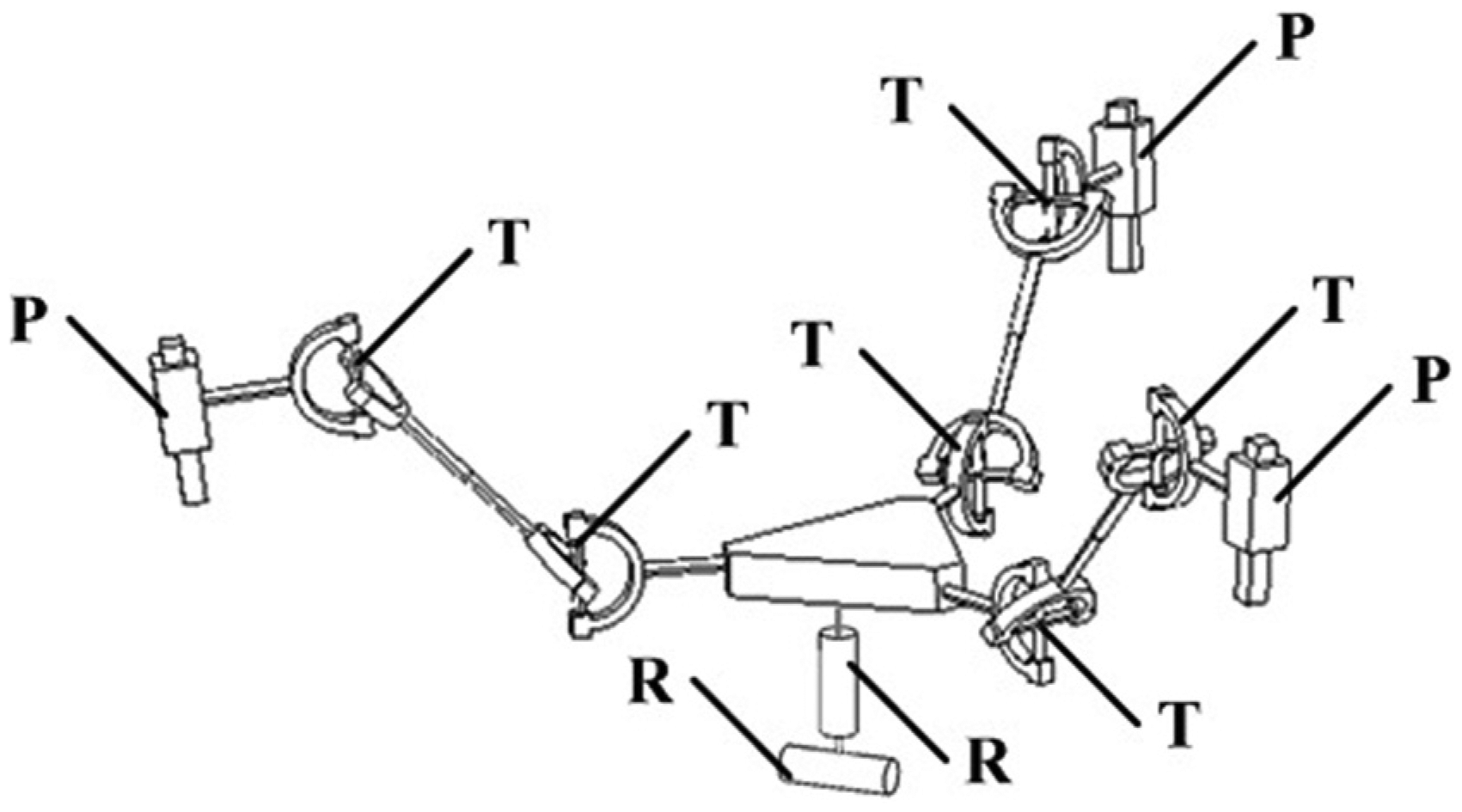
The sketch of mechanism for the designed serial–parallel machine tool.
The configuration for each component of the machine tool is designed on the basis of theoretical analysis for the mechanism. For the parallel machine tool parts, the top is driven by permanent magnet alternate current (AC) servo motor and transferred by gear and belt to drive the ball screw to rotate. Double connecting rod is connected to the movable platform, that is, six connecting rods, with a certain length in order to improve the system rigidity. The saddle moves to drive Hooke hinge to rotate and connects rod to move so as to realize the movement of moving platform. For the series part, the permanent magnet AC servo motor drives the moving shaft to rotate and the tool is installed at the end of mechanism to realize the machining process. The geometric model of the machine tool is shown in Figure 2.
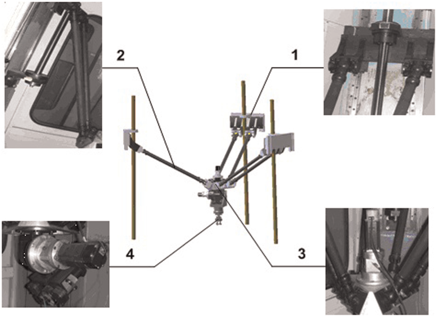
Model of servo feed system for serial–parallel NC machine tool.
According to the design of the serial–parallel NC machine tool geometric model and its motion rule, the problems of movement and force coupling relationship for the machine tool in the working process were studied. It is the dynamic coupling problem. The following will make the system analysis to solve this problem.
Analysis of dynamic coupling characteristics for 3PTT-2R machine tool
3PTT-2R series and parallel machine tools are compositions of typical kinematics pairs, and these pairs presented a strong coupling relationship between motion and force which makes the whole system present the complicated dynamic property. The mechanism dynamics is to study the displacement, angle, velocity, acceleration, position and other information for kinematics pair of each link and the relationship between known force and torque of driver input, and it is the key link for the mechanical properties of the system. The analytical mechanism implements the correct movement path in the precondition. The dynamic coupling analysis was made to the series and parallel parts of the machine tool based on the analysis of geometric model and kinematics characteristics for 3PTT-2R serial–parallel machine tool.
The key point of the dynamics is how to establish and solve the model for parallel and serial parts of 3PTT-2R mechanism. The main application process is as follows: first, to study the kinematics issue of mechanism and establish the kinematics coupling equation of parallel mechanism and then provide the basis for solving the dynamic coupling equations; second, establishing a dynamic coupling model of parallel mechanism to study the dynamic coupling of parallel mechanism; third, establishing the dynamic coupling model of series mechanism to study the dynamic coupling principle of serial mechanism. The main application method is, for the first step, to analyze the principle of movement angle for connecting elements of parallel mechanism and establish the relationship between motion track and angle coupling. As for the second step, the Kane equation method shall be applied first to establish the relationship between force and displacement and then to establish the system energy equation by Lagrange so as to get the dynamic coupling model. For the third step, the Kane equation method shall be applied first to establish the relationship between force and displacement and then the Lagrange equation method is applied to establish the system energy equation and obtain the dynamic coupling model.
Analysis of kinematics coupling characteristics for 3PTT parallel mechanism
The kinematics coupling problem of parallel mechanism was studied on the basis of establishing the machine tool model and analyzing the movement rule of mechanism. The coupling factors of 3PTT motion are caused by each link of mechanism. It mainly included the coupling between the screw and the sliding saddle, including inertia coupling, kinetic coupling and dynamical coupling. Connection coupling among the sliding saddle, Hooke joint and connecting rod includes the inertia coupling, kinetic coupling and dynamical coupling. The connection coupling among the connecting rod, Hooke and moving platform includes the inertia coupling, kinetic coupling and dynamical coupling. The analysis of the coupling problem was made as follows:
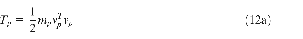
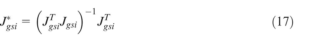
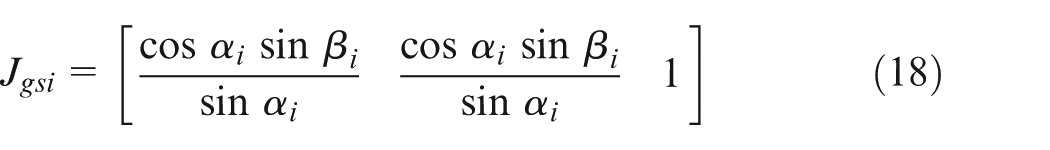
Determining the coupling relationship of mass system for mechanism. Suppose the inertial coupling between the screw and the sliding saddle is

where
Establishing the coordinate transformation matrix. The position of the moving platform can be expressed by the generalized coordinates of moving platform coordinate system with respect to the reference coordinate system, and the homogenous transformation formula for the position of the coordinate system is
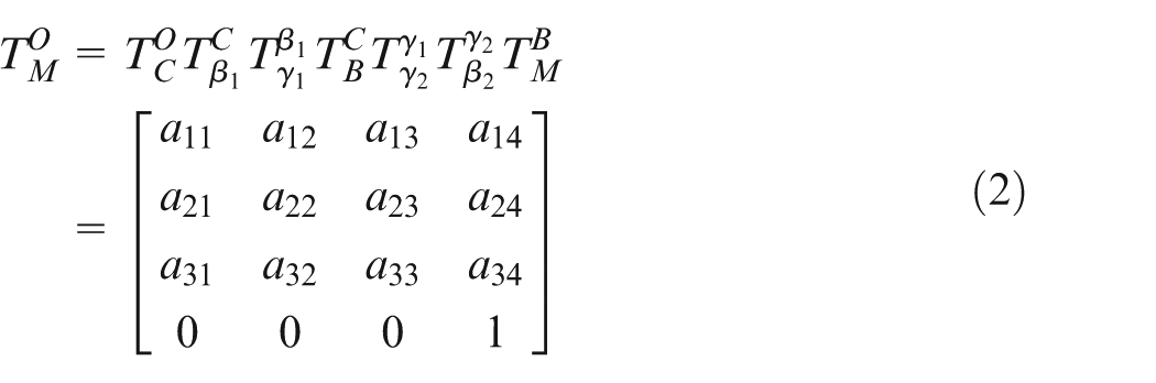
where
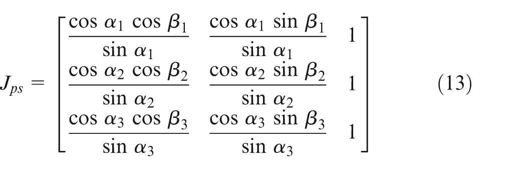
Analyzing the connection coupling for the Hooke joint. The three screws are defined as screw 1, screw 2 and screw 3; the corresponding upper Hooke joints are set as upper 1, upper 2 and upper 3; the corresponding lower Hooke joints are set as lower 1, lower 2 and lower 3; the corresponding rotation angle of the Hooke joint is determined by the structure of the Hooke joint. The position of the moving platform is horizontal, and the included angle to the horizontal direction among the upper Hooke joint, the lower Hooke joint and the connecting rod is determined by the movement displacement of three sliding saddles. Suppose the included angle of the connecting rod to the vertical direction is
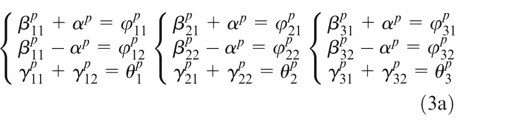
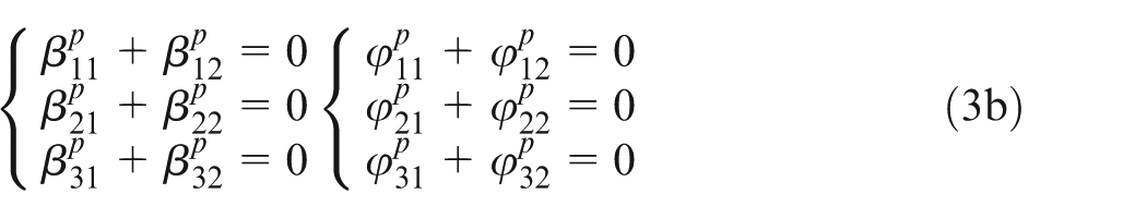
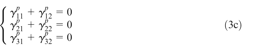
Equations (3a), (3b) and (3c) are used to solve the kinematics coupling problems of moving platform and get the solution on the basis of determining the relationship between coordinate transformation matrix and connection definition. The coordinate equation set model of moving platform center
that is, the kinematics decoupling equation; then,
Thus, the velocity and acceleration of the moving platform are obtained.
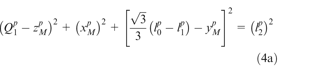
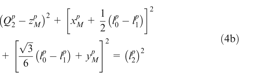
On this point, the moving platform kinematics equation can be expressed by formula (4). The random coordinate point equation and the equation of velocity and acceleration were established, respectively, that is, the 3PTT kinematics coupling relationship was established. The dynamic coupling model made for parallel and serial parts is as follows.
Analysis of dynamic coupling characteristics for 3PTT parallel mechanism
The force analysis of dynamic platform is required before establishing the dynamic coupling model, that is, the study on the mechanical coupling problem. The moving platform structure is shown in Figure 3(a)) and the force analysis is shown in Figure 3(b)). The platform was drawn by three connecting rods since the moving platform only makes the translational motion. There is no reversal action incurred. Therefore, at the junction of the Hooke joint for three vertices
The dynamic models of moving platform: (a) the assembly model of the moving platform and (b) the diagram of force vector of the moving platform.
The load and the joint driving force are confirmed by the principle of virtual work. The force equilibrium equation of the moving platform is established as
Then, the connecting rod force value is calculated as
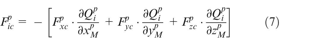
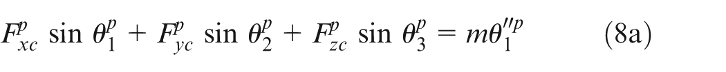
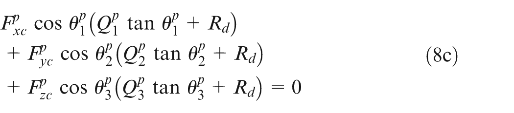
Under the work force of the machine, the external load force is transferred from the machining tool of serial mechanism to the moving platform. By the analysis of force, formulas (8a)–(8c) are defined as

Since the parallel mechanism used the double-end Hooke joint connection, the direction of the force acting on the connecting rod is along the vector of the connecting rod. The force along the connecting rod is resolved in three directions of the coordinate axis as
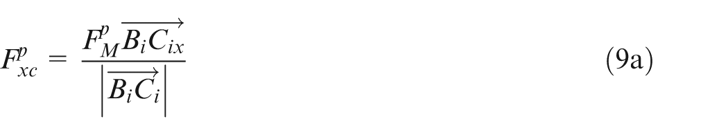
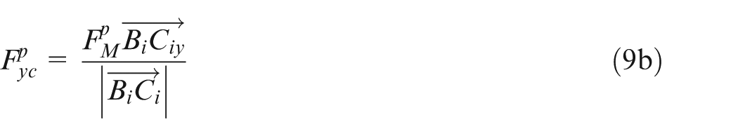
where
As the establishment of the model that shares the balance between the motion and force, the above process is based on the form of Kane equations. The Lagrange method is used below for solving the dynamic equation to characterize the relationship of energy moving platform.
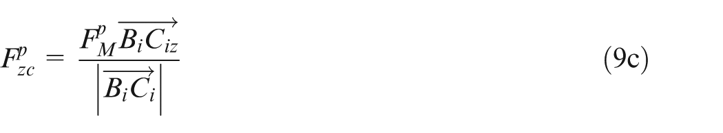
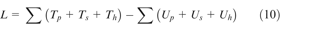
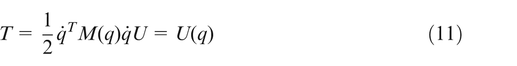
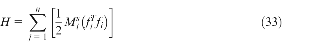
When the parallel mechanism makes spatial translational motion, the velocity direction is in the same plane of movement, and the kinetic energy of translation is produced. Meanwhile, due to the mass relationships, the vertical potential energy is produced.
1. Establishing the Lagrange function
Based on this equation, the serial and parallel mechanism includes static platform, screw rod, connecting rod, sliding saddle, Hooke joint, moving platform and serial machining tool. First, for the parallel part, wherein the static platform is stationary, the Hooke joint is used as the connecting element. The screw rod and the sliding saddle show the relative motion relationship, so the established Lagrange function is the energy relationship between the saddle and connect rod and the moving platform. The modeling analysis is made as follows:
1. Sliding saddle movement

where
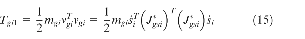
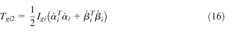
2. Motion of connecting rod.
The moving platform is created translational movement and the Hooke joint is used to connect the moving platform and the connecting rod. The connecting rod makes not only translational movement but also the space rotation. Then


3. Platform movement
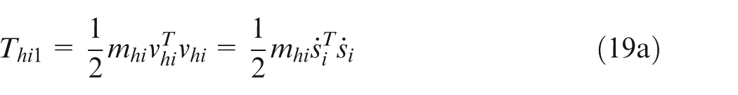

Thus, the Lagrange function is established as
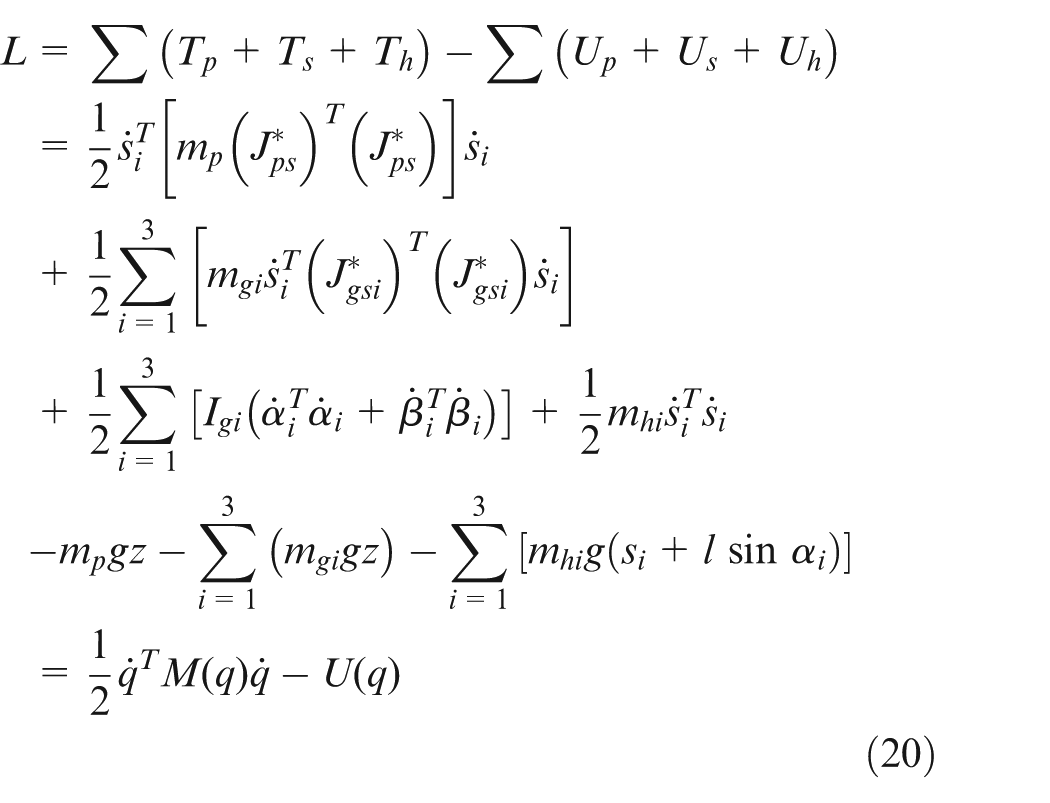
where
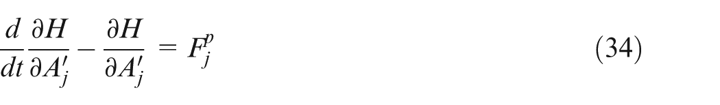
2. Solving kinetic equation.
The kinetic equation is in differential equation form, that is
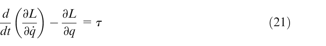
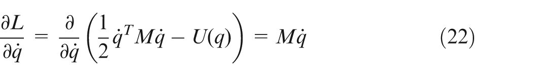
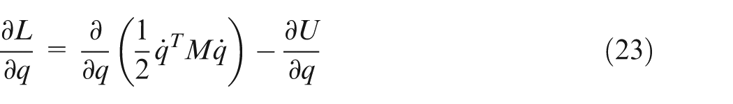
Thus, the kinetic equation is given as
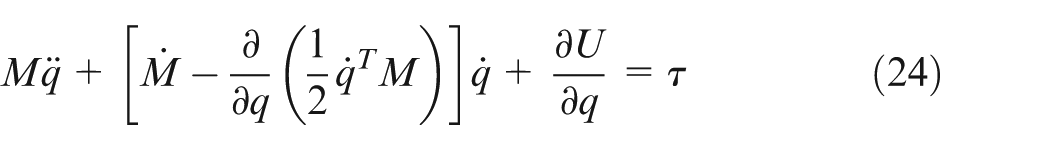
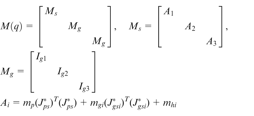
Expressed by inertial matrix

The dynamic coupling model of the parallel mechanism can be expressed with reference to formulas (4), (6) and (25). With the above model, the dynamic characteristics and rule on motion and force of the moving platform can be revealed, the coupling factors of connecting component for the mechanism can also be characterized, the dynamic characteristics of 3PTT mechanism can be presented properly and the systematic solution to the model parameters can be done; thus, the coupling problem between the parameters can be solved by the mathematical mode.
Then, the coupling relationships of force and position should be studied for 2R series mechanism so as to reflect the dynamic coupling characteristics of 3PTT-2R systematically.
Analysis of dynamic coupling for 2R serial mechanism
First, the coupling relationship for series part should be analyzed. As is shown in Figure 4(a)), 1 is the series unit 1, driven by the motor. It rotates around the z-axis and the length for the rotary shaft is h; 2 is the series unit 2, driven by a servo motor. It makes space swing around the y-axis. The length of the rotary shaft is still h and the swing angle with the vertical direction is
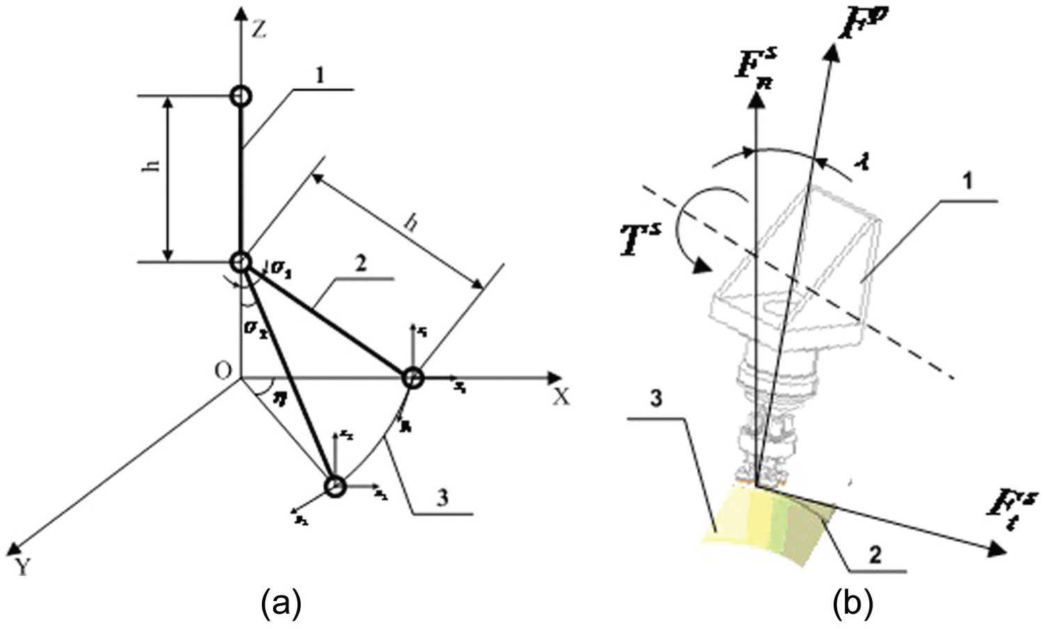
Dynamic coupling model of series mechanism: (a) analysis of diagram 1 of series mechanism and (b) analysis of diagram 2 of series mechanism.
According to the movement and force characteristics of the mechanism, the series mechanism comprises a rotating coupling mechanism in series mechanism 1 and series mechanism 2. Also, they include the inertia coupling, movement coupling and dynamical coupling characteristics, respectively.
Taking the arbitrary machining surface as the research object and the trajectory of machining tool is free curve without the loss of generality. The mechanism has 2 degrees of rotational freedom; the instantaneous machining state is determined by a degree of rotational freedom. It is the instantaneous tool posture angle. The instantaneous machining track is determined by the moving platform track. Therefore, in the serial mechanism, only the coupling relationship between the force of instantaneous tool and motion angle needs to be considered. The model of machining tool position angle and load force is established as shown in Figure 4(b)).
This article analyzed the dynamic coupling problems of 2R serial mechanism and still used the parallel part modeling for solving methods. The Kane equation was first used to solve the general regularity equation of dynamics and then the Lagrange method was used to express the energy relationship. The specific process is as follows.
Since the serial mechanism is only for connection of two components and can be deemed as a particle system with 2 degrees of freedom. Therefore, a generalized coordinate matrix is set as

Then
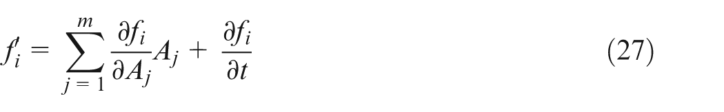
The dynamic coupling model is used to characterize the Kane equation, and the general dynamic formula of the Kane equation can be drawn as
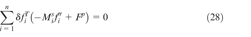
The function expressed by the virtual displacement and generalized coordinate functions is
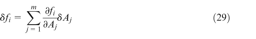
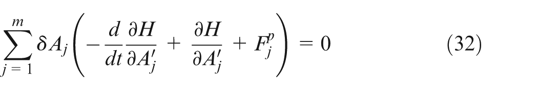
To sum up, the general dynamic coupling equation of the serial mechanism expressed by the Kane equation is
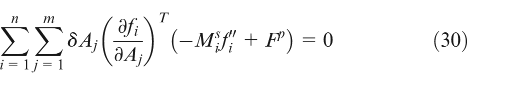
The below continually used the Lagrange solving method by energy representation form to build dynamic coupling model of series mechanism. The Kane equation is used to solve the process; Thus
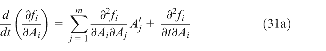
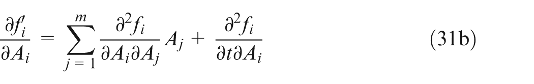
Substitute into formula (30) and get
where
Thus, the coupling model of Lagrange dynamic is obtained
To sum up, the coupling problems of dynamics for the series mechanism are the calculation problem between the instantaneous force and speed, thus further being studied as the coupling problem between the motor input and processing state. At the same time, this also echoed the coupling problem of dynamics for the parallel mechanism and further showed that the coupling relationship existed between the end force and position of system. The coupling factors are derived from the position angle between the motor input and the system actuator.
The above is for the solving and analysis of the coupling characteristics of dynamics for 3PTT-2R mechanism. The below focuses on the extraction and analysis of dynamic coupling factor for 3PTT-2R serial–parallel servo system based on singular constraints and position coupling factors so as to express the dynamic coupling problem in complete significance.
Analysis of coupling factors and position limit for 3PTT-2R serial–parallel mechanism
In order to accurately determine the working space, the operating track and dynamic characteristics of the serial–parallel machine tool during the working process should be analyzed. The coupling factor, the position and position limit which influence the machine operation must be found out so as to properly express the real work process of the machine tool. The specific items include the following:
Restrictions of moveable length
It must suit
Limit of positive and negative angles for the Hooke joint
The angles for all kinds of hinges, including the spherical hinge and Hooke joint, are restricted by the structure, and the maximum allowable angle of the different hinge structures is not the same. Therefore, the mechanical structure of the Hooke joint should be analyzed. In the second part, the analysis of the parallel mechanism, the upper Hooke joint is distributed to the static platform inscribed circle and the lower Hooke joint to the movable platform inscribed circle which determines the motion scope of strut connected to the Hooke joint. Seen from the geometric relationships of the Hooke joint, the Hooke joint is divided into front angle and the side angle, corresponding to the two planes,
The interference of the overall dimensions for this machine tool.
For different serial–parallel machine tools, the structure is not identical and whether the operating range of the moving platform is restricted by the surrounding frame limits is not the same in difference. The connecting rod of 3PTT-2R serial–parallel NC machine tool is designed as the fixed length. The freedom of space movement for the moving platform is

Position limit
The boundary search method and the effective envelope method are used jointly during the process of solving the motion path and workspaces for the machine tool. In the solving process, the specifically related position limit includes the following:
Position Limit I
In accordance with the search method, the value of z is given and the the boundary value along z one by one is searched For any position at
When the center of the moving platform is located at the intersection, the moving platform size (i.e. the circumradius) intervenes in the size of the inner edge of the machine tool. The interference point is at limit position.
The machine tool control platform actually relies on the six connecting rods. Any branch is controlled by two rods, and each is connected by the two upper and lower Hooke joints. So when the moving platform center is located at the intersection; the front and side angles of the two upper and lower Hooke joints shall be calculated, respectively, so as to determine whether the swing block of Hooke joint intervenes in the base of Hooke joint and whether it intervenes in the moving platform edge and whether it intervenes in the connecting rod, that is, the angle limit position of the Hooke joint. Structural dimension of the platform and Hooke joint includes the diameter of the connecting rod. The distance of screw is that it is in vertical position of the connecting rod and the limit position of moving platform.
Reverse solving whether the movement meets the requirements when the driving screw rod moves to any position of
Position Limit II
In accordance with the effective envelope method, it takes the movement length of the driving screw rod, front and side angles of the Hooke joint and the workspace boundary problem for the overall size of the machine tool to the intersection problem for three envelope surfaces of variable spherical group. For any connecting rods, the connecting rod and Hooke joint have the following relationship expression
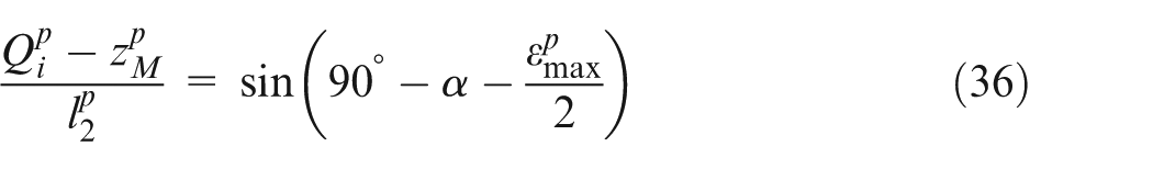
Position Limit III
Since the machine tool contains a serial unit that it is terminal actuator, the formula is

The reason for the “<” rather than “≤” is that, in the actual machining process, the height of the working table needs to be considered, that is, the limit position of the moving platform center in z coordinates.
In order to verify the correctness of dynamic coupling analysis theory, the following will conduct the system dynamics simulation analysis and the numerical simulation and parameter simulation analysis, respectively.
Simulation of dynamic coupling
Dynamic simulation plays an important role in research and application of 3PTT-2R serial–parallel machine tool. The reference value through the dynamics coupling simulation of the moving platform and tool can be provided. This article took numerical and parametric simulations of 3PTT-2R mechanism, and the aim is to prove the method of simulation correct.
Numerical simulation of mechanism
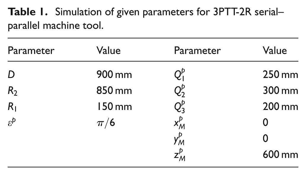
The numerical simulation of mechanism analysis is classified into simulation analysis of working space and the movement track. First, based on the singular constraints and coupling factors mentioned above, in combination with the dynamic coupling model of the machine tool, the relevant parameters of simulation were entered, to conduct numerical solution of the working space, so as to get the actual working space of 3PTT-2R mechanism; the parameter value is shown in Table 1, the flow diagram is shown in Figure 5 and the numerical simulation of the working space is shown in Figure 6.
Simulation of given parameters for 3PTT-2R serial–parallel machine tool.
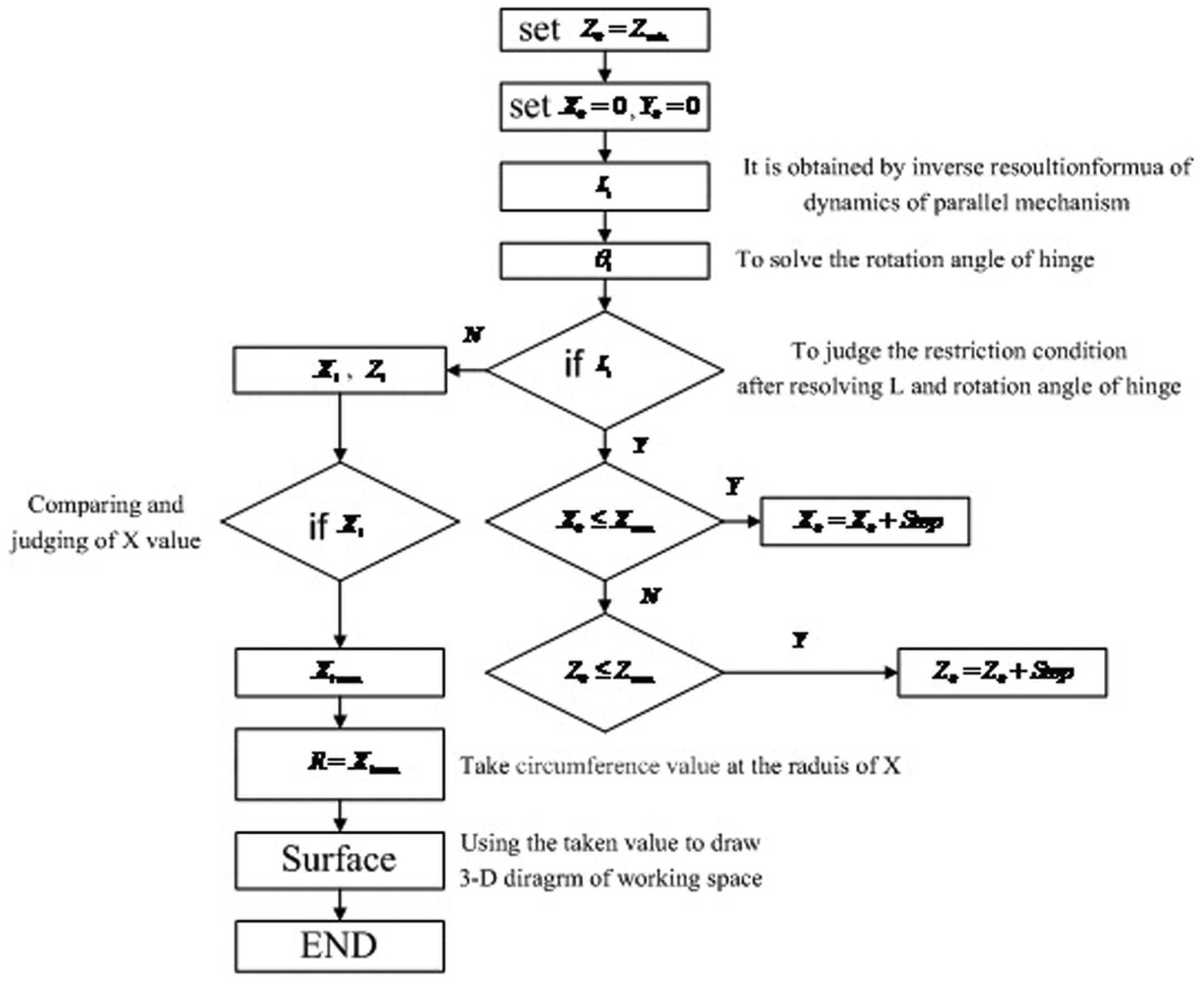
Solution flow chart of working space.
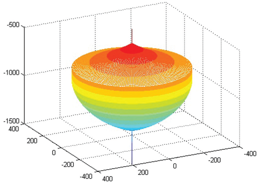
Working space of moving platform.
The a spheric surface was taken as the numerical simulation example to plan the motion track of 3PTT-3R serial–parallel NC machine tool. The dynamic characteristics of serial, parallel, position limit and coupling factors were checked by the dynamic model of machining simulation, and the parameters of model were revealed comprehensively so as to achieve the reasonable matching of kinetic parameters. Figure 7 shows the simulation results of dynamic coupling numerical model.
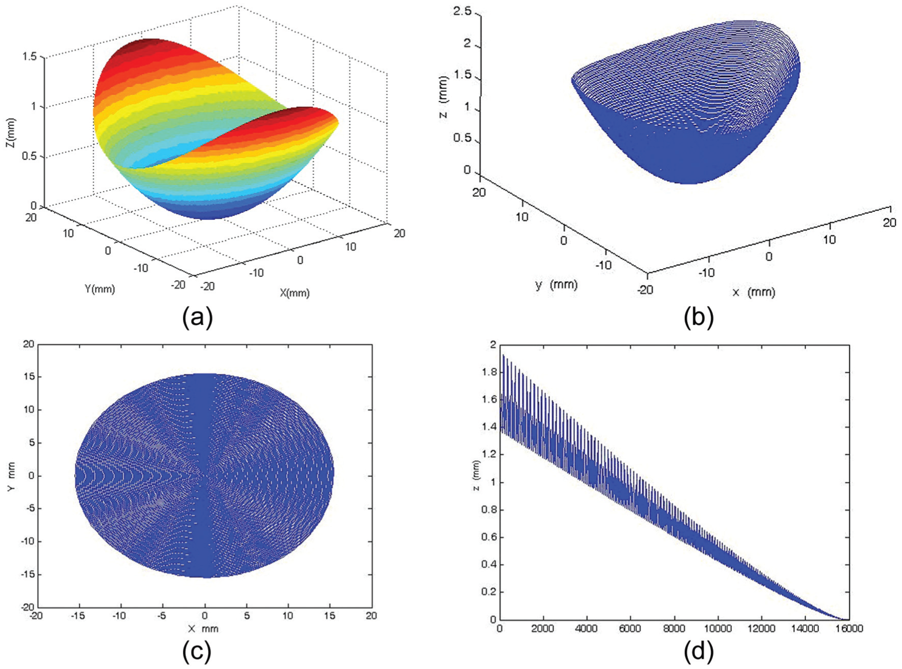
Simulation result of dynamic machining for 3PTT-2R machine: (a) curved surface feature, (b) tool path, (c) tool path projection and (d) dynamic curve in z-direction.
As seen from Figure 6, the workspace shape is similar to a semi-elliptical sphere, but its boundary is not of complete elliptic shape. It is different from the elliptic shape of theoretical workspace graphics. The theoretical workspace only considers the center moving track of the moving platform, and the actual 3PTT-2R serial–parallel NC machine tool has its own post limit and singularity, so in the process of simulation, the space mechanism problem is converted into the simple intersection of math. The influence factors in the process of operation are considered, and the interference condition is judged. The simulation result for the boundary of the working space is incomplete elliptic shape by considering that the mechanism itself has a limit position and position coupling factors. The output data obtained are within the effective range of parameters and the boundary is smooth. It is not inside the cavity. The working space can fully reflect the issue of actual machining range and reflect the working space coupling characteristics on the basis of considering the serial–parallel mechanism factors. Describing the issues existing in the working space of serial–parallel mechanism only by theoretically calculating the working space, the working space of parallel mechanism or not considering the coupling factors of the working space in the past is solved and set as a basis to further solve the mechanical decoupling issue of serial–parallel mechanism.
It shows the simulation result of dynamics coupling model as in Figure 7. It is the simulation of machining a given surface by 3PTT-2R machine tool. It shows the free-form surface and traverses all the surface data according to the movement motion of the machine tool (screw) in Figure 7(a). The numerical simulation of mechanism, as equations (4) and (24), is taken and the results are shown in Figure 7(b) and (c). Figure 7(c) is the projection of Figure 7(b) on xoy. It is added to vibration characteristics for tool in Figure 7(d) and its aim is to simulate the situation of the cutting force. The surface feature (Figure 7(a)) and tool path (Figure 7(b)) are in good conformance, and the degree of approximation to the aperture is good, showing that in the process of simulation, traversing data conform to the movement rule. As seen from the plane projection (Figure 7(c)), data vary with the radius change, and they also reflect that in the simulation process of the mechanism movement. The simulation motion data match the ideal surface properly. The motion track of the moving platform is accurate and complete. There is no singular or missing point, showing that no interference phenomenon exists. The linearity of simulation rule in z-direction is good. It shows that the force reduced gradually along the surface contour in z-direction and it conformed to dynamic characters of the machine tool. The curve and surface axial depth are in good conformance, and the track numbers are in line with the actual processing needs. Achieving the simulation characteristics of real machining state reflected the motion characteristics and coupling condition properly. It can be proved that the kinematics coupling characteristics and working space and singular constraints and position coupling factors are correct. To sum up, the dynamics characters for processing surface part of 3PTT-2R machine tool are better simulated.
Parametric simulation of 3PTT-2R mechanism
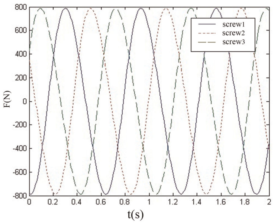
The structural parameters of 3PTT-2R serial–parallel machine tool are shown in Table 2. The kinetic parameterized simulation of the serial–parallel mechanism in the typical working conditions is made, respectively, by establishing the virtual prototype. The results are shown in Figures 8 and 9. Three curves represent the upper Hooke on the three screws of the parallel mechanism as shown in Figure 8. The z direction points of tool force were shown in Figure 9.
Simulation analysis parameters for serial–parallel machine tool.
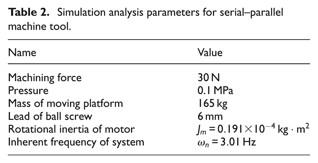
Force curve of the upper Hooke.
Force curve of machining tool operation.
As shown in Figure 8, the force curve of two-way Hooke joint is connected to three screws of the parallel mechanism which is in uniform sine and cosine law while the machine tool is in the process of movement. The periodic operation is stable and the amplitude force movement is within the reasonable angle scope of the Hooke joint. There are no singular points or large dynamic errors caused by the force. Thus, it can be concluded that the dynamic coupling error is smaller for the key connectors of the machine during the machine tool motion process. Figure 9 shows the force curve of the machining tool for serial mechanism and the force variation trend due to external load of machining. As seen from the figure, when the tool touches the workpiece, the force is less and stable which is due to the slow feed rate and small cutting amount. After that, in the gradual cutting process, the force of the machining curve caused by the surface is not even in the machining process. The overall trend of the curve is in reasonable force range, meeting the force requirements of the machine tool in the machining process.
The purpose of simulation is to simulate the kinematics and force through the two methods of numerical and parameters. Whether there is singular position and larger coupling error in the working process of the machine tool is determined. Not only it has good verification for the dynamic coupling model but also has a certain guiding significance for the next machine tool processing. At first, the article calculated the working space of the machine tool and considered singularity position and coupling factors. And then the analysis of simulation is taken. Next, the working space is confirmed as is shown in Figure 6. Second, the article took the dynamic simulation of 3PTT-2R machine tool as an example of machining complex surface part. The point movement process of the machining part is dynamically simulated on the basis of the mechanism of the machine tool. The machining form is screw processing. The z-direction is added to the process of the simulation to simulate the force of the tool which can be seen in Figure 7(b)–(d). Finally, the article has carried out the force simulation of the machine tool and set the cutting parameters on the basis of the trajectory of machine tool processing which is aimed to prove that the established dynamic coupling model is correct. It has an indirect guiding significance for cutting depth of tool in the next experiment, as shown in Figure 9.
Experiment
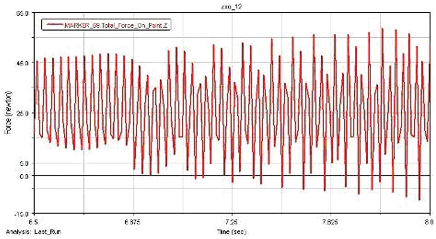
The experimental conditions: 3PTT-2R NC machine tool, the parameters also has been reflected in the revised manuscript. The material is silicon, diameter is 40 mm and the geometry is cylindrical. The experiment is conducted under the condition of normal temperature (20 °C) for processing the environment. The result shows that the precision is high and has reached nanometer level in some place of the machining part as shown in Figure 10(a). The roughness of the part surface is better in the detection of 100 μm; it is −0.002 to 0.003 μm as shown in Figure 10(b). It shows that the machining precision is higher and the movement is accurate; the machine tool can move all the data of the designed surface in the machining process and there is not singular position and larger coupling error. It can be proved that the theoretical analysis of the working space and the established kinematics coupling model and the singular constraints and position coupling factors are correct. It does not have any dynamic fault and the machining part of the machine tool is better finished. It is the three-dimensional (3D) contour of the part in the detection area as shown in Figure 10(c). It can be seen that the green interference fringes are symmetrical and there is only a few red and the overall profile is better. It shows that the movement and force are smooth and do not appear to have larger vibration and deviation in the working process of the machine tool. It proved that the established cutting force model of the serial mechanism is correct. The cutting force figure of the tool (Figure 9) can indirectly match the interference fringes and can prove that the simulation is reasonable. To sum up, the experiment of this article can prove that the dynamic model and the simulation are correct. Table 3 lists the experimental conditions.
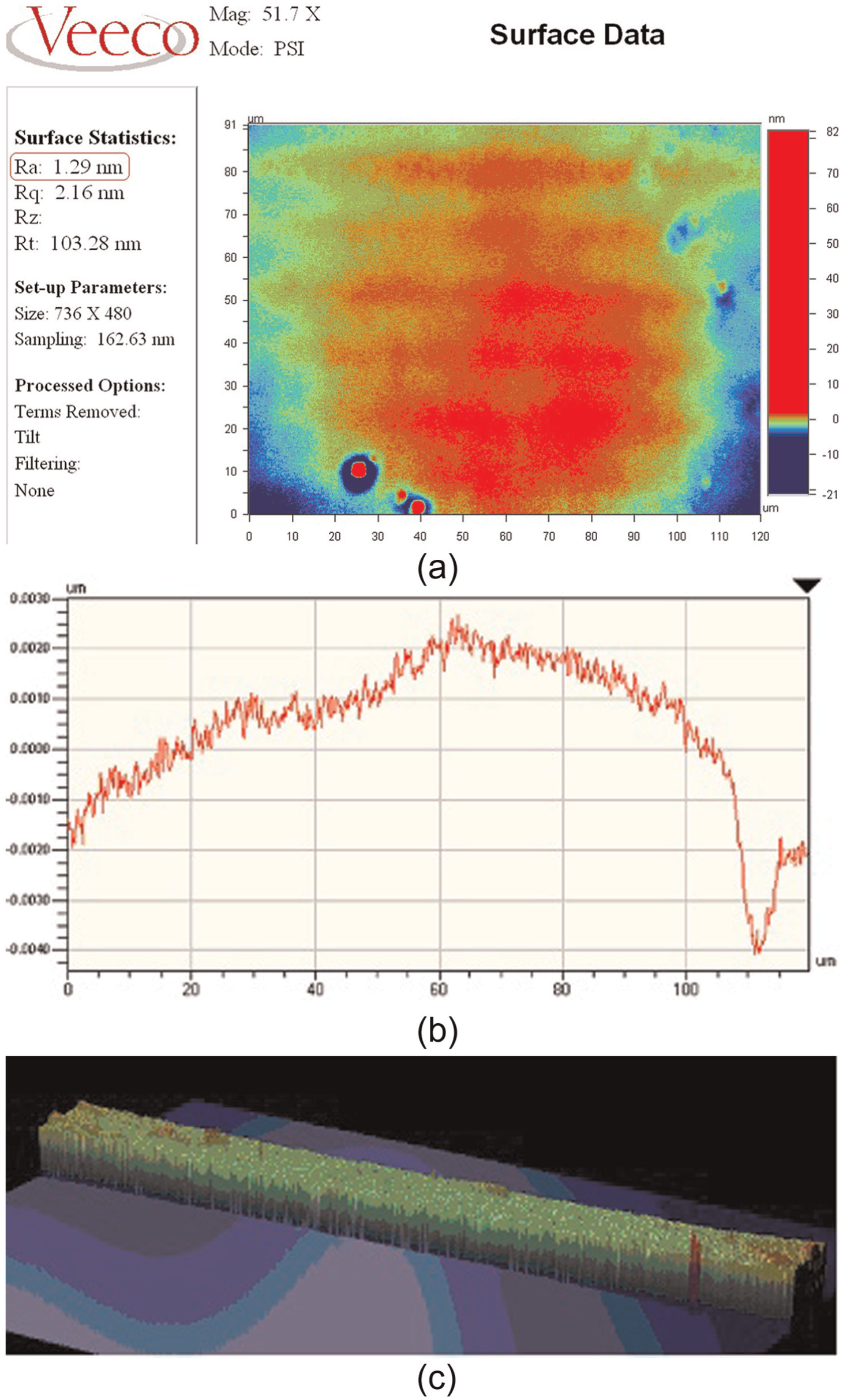
Partial test of interference fringe for machining sample: (a) surface test results for machining parts, (b) roughness test results for surface of machining parts and (c) profile tolerance test results for surface of machining parts.
Experiment conditions.

It is intended to judge the dynamic coupling characteristics by the motion state and precision of the machining parts. To analyze the test results, it selected the optimal experimental parameters and the optimal parameter for grinding to verify the correctness of the dynamics coupling analysis.
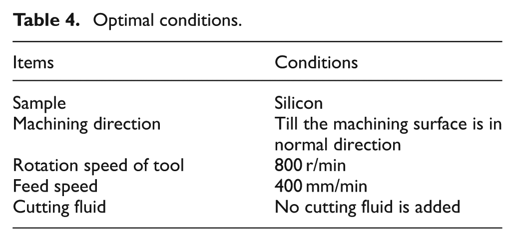
First, the experiment is carried out to study the effect of cutting process on machining process and precision. The theoretical research of dynamic coupling analysis is verified by machining tool cutting force and the optimal cutting speed test. Changing the pressure and cutting speed, the parameters of force and speed on the processing precision of the workpiece is optimized. Table 4 shows the optimal conditions The data are obtained by the mathematical treatment of test. The results show that the machining is smooth, the curve is stable and the working process is suitable and stable. There is no larger singular coupling error and the machining accuracy is good, and the cutting effect is ideal in this process of cutting.
Optimal conditions.
Second, conduct precision inspection test for the machining parts. Monocrystal silicon is used as the machining material in combination with the control system parameters and the measured surface roughness by Wyko. The grinding results are shown in Figure 10. Figure 10(a) shows the projected result of measuring the shape of the workpiece surface. The machining part is free-form surface and it has processing requirements in the depth direction. So, the result of Figure 10(c) is the interference fringes of the part after taking laser scanning. The surface roughness of the part as a whole is shown in Figure 10(b), and it can be reflected by interference fringes as shown in Figure 10(c). The accuracy is reflected. The red fringe is poor and the green is better.
The purpose of the experiment is to prove that the dynamics coupling model and the force of tool and coupling factors are correct. At first, the movement of the machine tool in the process of the experiment is smooth and there is no large singular position and coupling error, no interference of Hooke and the fault of the length of the connecting rod. This can prove that the theoretical model and working space simulation are correct. Second, the surface precision of the machining part is high as shown in Figure 10(a) and (b). The cutting precision can reach nanometer level and the surface roughness is in overall curve shape and surface profile morphology is regular. This shows that the machine tool can move all the data of the designed surface in the machining process, and this result corresponds with the numerical simulation of screw trajectory. This can prove that the process and results of dynamic simulation and the kinematics model are correct. Finally, it can be seen that the interference fringes are consistent with part contour and green is symmetrical, and there is only a few red through the 3D profile of the part. It shows that the cutting force is smooth in the process and there is local cutting vibration just in the process of beginning and ending. The surface morphology is integrated and conformed to the requirements of processing as shown in Figure 10(c), complying with the requirements of the surface morphology for machine tool processing. The accuracy of the overall stripe is high, in good conformance with the machining track, which can reflect the exact relationship between force and motion for the machine in the process of cutting. It proved that the serial coupling model is reasonable and also corresponds to the force of the tool in parametric simulation. It can correspond to the interference fringes and the simulation of the cutting force. To sum up, it can be matched and a close proof between the established model and simulation and experiment can be obtained. The dynamic coupling problem can be solved properly, and the correctness of previous theoretical analysis and simulation is verified.
Conclusion
This article studied the problem of dynamics for 3PTT-2R serial–parallel NC machine tools and further studied the position limit and coupling factors of the machine in the process of working, and the working space was obtained. In the dynamic analysis of the coupling process, the kinematics and dynamic model of parallel mechanism and series mechanism were established by Lagrange and Kane equations. The parameters and kinetic parameters of machine movement were reflected. The working limit position involved in the working process and the coupling factors of connecting parts influencing the machine operation were determined by analyzing the related size of machine tool motion, angle and the equation solving process itself. It is mainly reflected in the working characteristics of Hooke joints connected. The analysis method and process in this article can not only definitely express the dynamic model of 3PTT-2R serial–parallel mechanism but also reasonably analyze the rule of value and range of dynamic parameters which provided the reference and basis for the precise control of the joint simulation system and the actual machining process. The comprehensive application of this boundary search method and the effective envelope method simulation system were made for the working space and processing character simulation to verify the validity of position coupling analysis and correctness of dynamic coupling model. The simulation results showed that the dynamic coupling model was correct, position limit was reasonable, servo system operated smoothly in the movement process, the movement speed was high, with no larger singular state and coupling error, and the relationship between the force and velocity conformed to the dynamics rule.
On the basis of theoretical analysis and the machining experiment, it was shown that the machine working state was stable, and the operating trend was regular with no collision and interference conditions. The interference fringes of machining showed that cutting ability was good and the precision was high, in good conformance with the machining path which could reflect the exact relationship between force and motion for the machine in the process of cutting, solve the dynamic coupling problem properly and verify the correctness of previous theoretical analysis and simulation.
For the next work, the coupling relationship between the machine power and control will be further analyzed, the electromechanical decoupling control method will be gradually studied and the calibration of machining contour tracking control and parameter will be taken to provide the basis for solving the electromechanical coupling problem of a kind of serial–parallel servo system.
Footnotes
Appendix 1
Declaration of conflicting interests
The author(s) declared no potential conflicts of interest with respect to the research, authorship and/or publication of this article.
Funding
This article was supported by the Ministry of Education of New Century Talents Support Plan of China (No. NCET-12-0731) and the National Natural Science Foundation of China (No. 61374138) and the Jilin Province Education Science Foundation of China (No. 2012111).