
Abstract
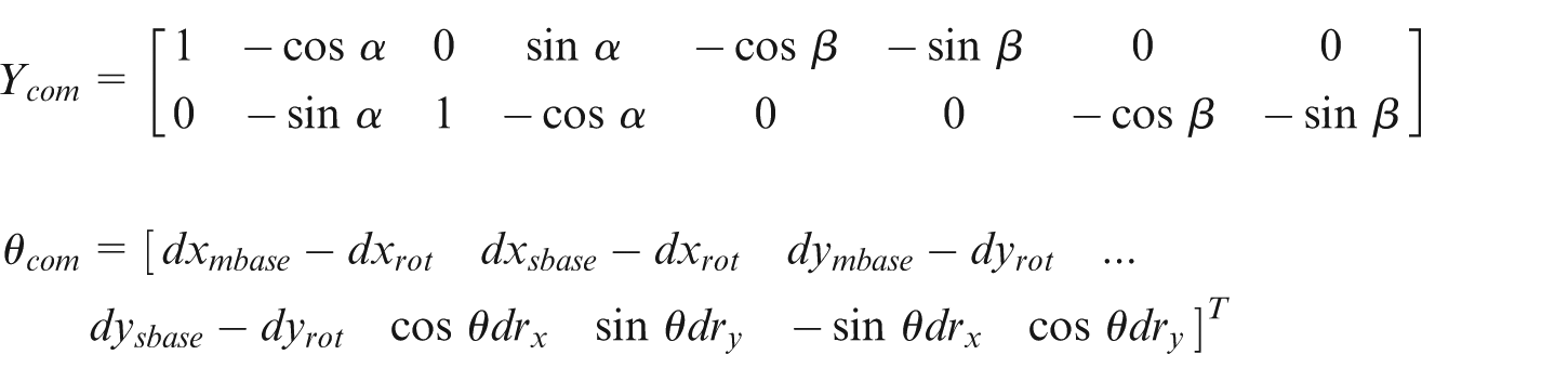
This study developed a novel error compensation method aimed at eliminating placement error caused by hand–eye calibration and pick-and-place tool motions in automatic stiffener bonder for flexible printed circuit. Using the transformation of homogeneous coordinates to develop an error model of the system describing the coupling of errors among various coordinate systems, the least squares method is used to calculate the unknown model parameters. The experiment results demonstrate that this error compensation method reduced placement error by an order of magnitude. The mounting precision throughout the entire work area was ±0.046 mm at 3sigma, and for flexible printed circuit products with a specification limit of 0.1 mm, the process capability index of the automatic stiffener bonder in this study was 2.19. This represents that the system is capable of fully satisfying the precision requirements of flexible printed circuit stiffener bonding. The proposed system employing a vibrating feeder bowl and machine vision–aided target positioning is applicable to a variety of stiffeners, which enhances production flexibility. The proposed error model considers the complex coupling effect of the errors among multiple coordinate systems in hand–eye calibration, without the need of detecting and calculating the calibration error item by item, and takes into account the errors produced by the rotation and downward pressing motions of the pick-and-place tool.
Keywords
Introduction
Flexible printed circuit (FPC) boards require stiffeners to increase rigidity in specific areas; 1 however, inaccuracy in the placement of stiffeners can lead to defects in the resulting product. 2 Machine vision can be used to assist the automatic stiffener bonders (ASBs) in precise positioning in order to achieve high-speed, precision bonding; however, this approach requires calibration to eliminate errors.3–5 First, laser interferometers, step gauges, and double ballbars are commonly used to measure and calibrate geometrical errors in motion mechanisms, in order to enhance precision in control.6–10 Second, hand–eye calibration is also required to rectify errors in the transformation between coordinate systems, which is equivalent to solving matrix equations of the form AX = XB. Obtaining the unique solution of the equation necessitates the inclusion of specific constraints during the calibration process.11,12 For example, the robots must perform three mutually orthogonal translations. 13 Zhuang proposed a hand–eye calibration method for the Selective Compliance Assembly Robot Arm (SCARA) robot with 4 degrees of freedom (DOFs). That study demonstrated that decreasing the number DOFs that can be controlled makes it impossible to obtain the position vector about the Z-axis in the solution space. 14 Furthermore, nonlinear optimization is required to mitigate the effects of noise and measurement error during calibration.15,16 The varying number of DOFs among various devices has prevented the development of a unified approach to solving problems associated with hand–eye calibration, and the large number of constraints further complicates calculations.
Hand–eye calibration has been simplified in practical planar operations that are similar to mounting processes by focusing on problems associated with the transformation between two two-dimensional (2D) coordinate systems.17,18 Surface mount technology (SMT) uses equipment similar to that of ASBs in which motion mechanisms comprise Cartesian coordinate robot. Zupancic 19 used linear displacement transducers to measure positional error in one-dimensional motion for the calibration of SMT systems. Shih and Ruo 20 devised a rapid hand–eye calibration approach for SMT systems without the need for additional measurement equipment. However, this method fails to deal with the errors resulting from manual operations in which pick-and-place tools are moved to the location indicated by the fiducial marks. First, the robot is manually operated to move the tip of the stylus mounted on the tool to the center of the fiducial mark, in order to obtain the coordinate of the fiducial mark.17,18,21 Second, as the calculation of the stylus coordinate is based on the calibration of the tool coordinate system, 22 the calibration error of the tool coordinate system results in the measurement error and the measurement error is propagated to the hand–eye calibration results. In addition, the use of cameras to measure positional errors caused by pick-and-place tool rotation does not consider the influence of pressing motion associated with the pick-and-place tool.23,24
Accompanying the expanding scope of FPC applications is the increasing diversity in stiffener materials. At present, most automatic stiffener bonders for flexible printed circuits (FPCASBs) use easy-to-punch materials such as polyimide (PI) film. 25 The feed systems in conventional ASB equipment punch out the stiffeners directly. The position and direction of the punching mold are fixed, such that the total placement error caused by the errors in hand–eye calibration is fixed. Thus, the error can be eliminated simply by setting a corresponding offset value.
For other types of stiffeners that are not easy to punch, the bonding process is entirely manual, which makes it nearly impossible to guarantee precision and quality. To address this issue, this study proposed a system employing vibrating feeder bowl and turntable as the feeding component; this makes it suitable for a variety of stiffener materials, including PI, metals, and epoxy glass. This system helps to bridge a gap in the FPCASB industry, but brings some new technological issues affecting the placement precision. First, the feeding component developed in this study increased the variation in rotation angle of stiffeners during the mounting, so that the variation in rotation angle caused the changes in placement error. The coupling effect of the errors from multiple coordinate systems increases the complexity associated with the elimination of the error. Second, the use of conductive adhesives in the bonding of stiffeners means that when a stiffener is mounted, the pick-and-place tool must heat and press down on it. This strong downward force can increase positional error caused by rotation of the pick-and-place tool; this positional error is difficult to measure directly.
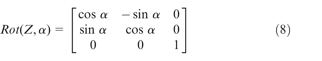
This study developed a novel error compensation method aimed at enhancing mounting precision by eliminating placement error caused by hand–eye calibration and the motions of the pick-and-place tool in ASB. The flowchart of the compensation procedure is shown in Figure 1. Homogeneous transformation coordinate is used to develop a kinetic model associated with the robot and the machine vision component. 26 Using transformation to describe the coordinate of the stiffener after rotation and its placement location in different coordinate systems, the motion pathway is calculated for the controller. The placement error model of the ASB system is developed and the placement errors are compensated in the system, without the need of detecting and calculating the calibration error item by item. The effectiveness of the proposed model was verified in the experiments. Unlike conventional FPCASB equipment, the proposed system can be adapted to various types of stiffener, thereby enhancing flexibility in production. The proposed error model considers the complex coupling of hand–eye calibration errors in multiple coordinate systems and takes into account the errors produced by the rotation and downward pressing motions of the pick-and-place tool.
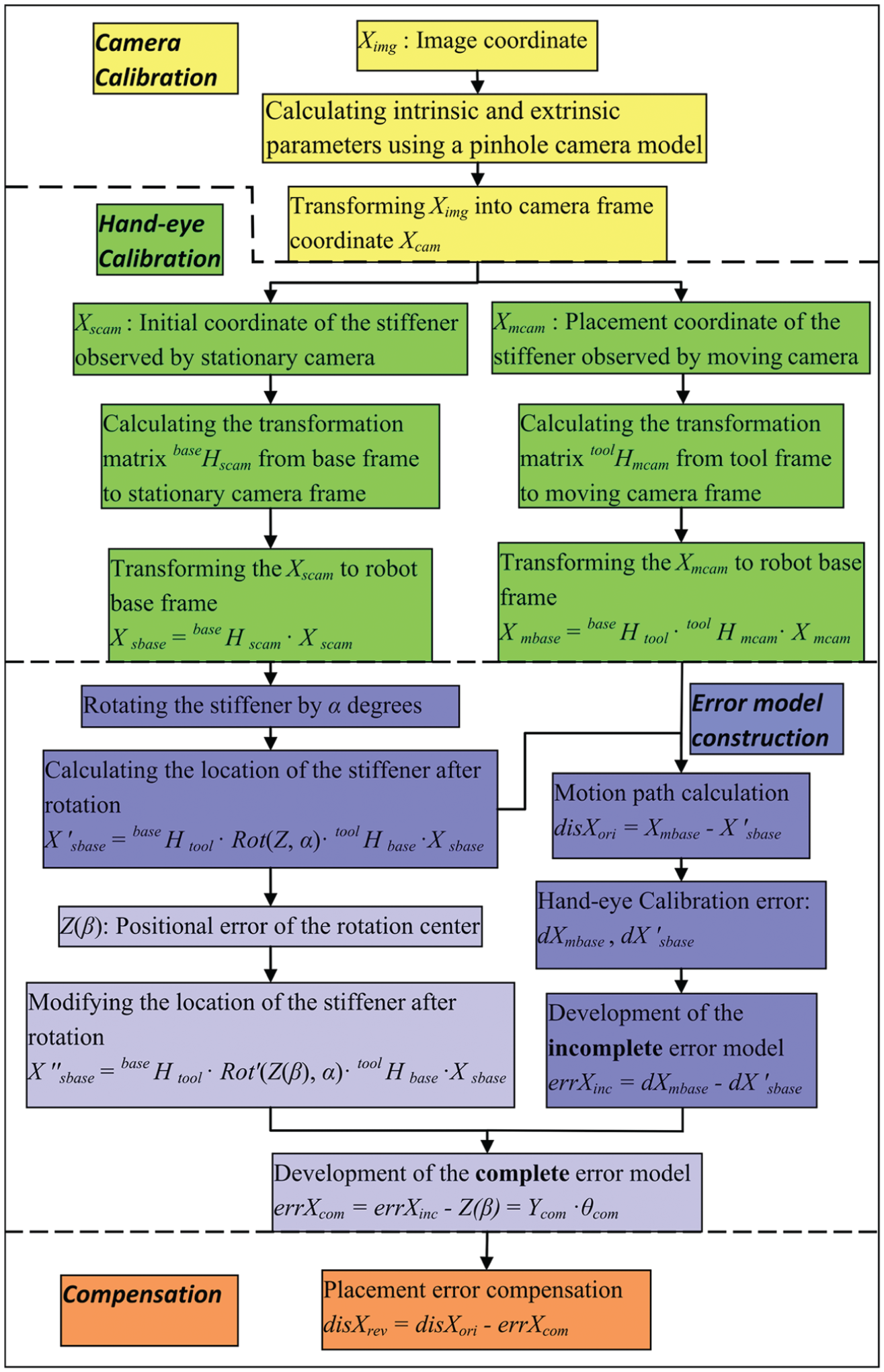
Flowchart of the compensation procedure.
ASB calibration method
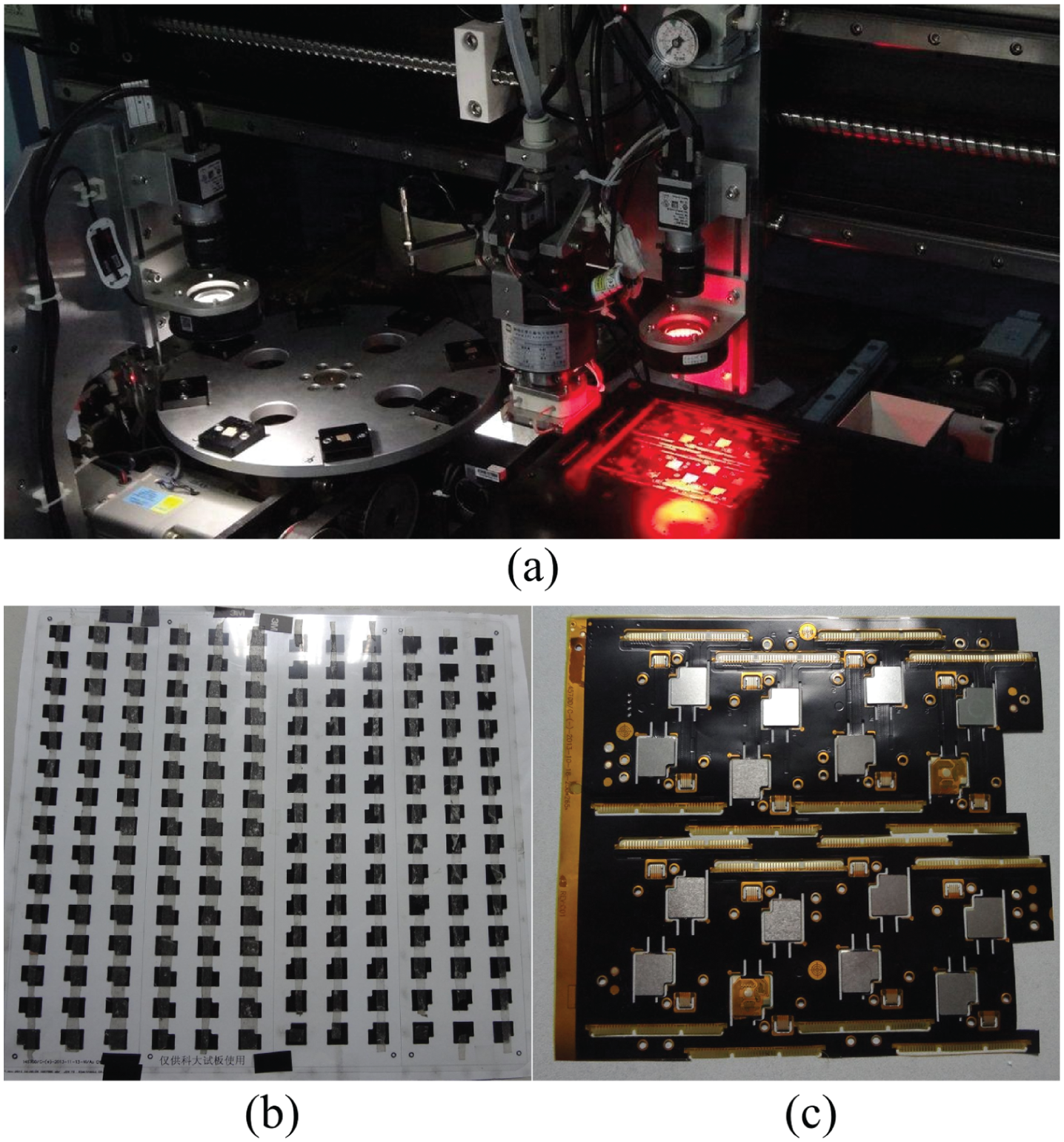
The ASB system designed in this study comprises three components, as shown in Figure 2. In the first feeding component, the stiffener is screened and palletized using a turntable conveyor. The second component is the motion mechanism with a Cartesian coordinate robot. The stiffener is handled by a pick-and-place tool, which moves along the X-axis and rotates around the Z-axis. A vacuum platform moving along the Y-axis is used to grasp the FPCs by suction. The X–Y plane of the robot base frame is used as the working plane, which is on the same plane as the vacuum platform. The third component is the machine vision system, which includes two high-resolution cameras. A moving camera positions the location of the stiffener mounted on the FPC, and an upward facing stationary camera positions the original location of the stiffener (attached to the pick-and-place tool).
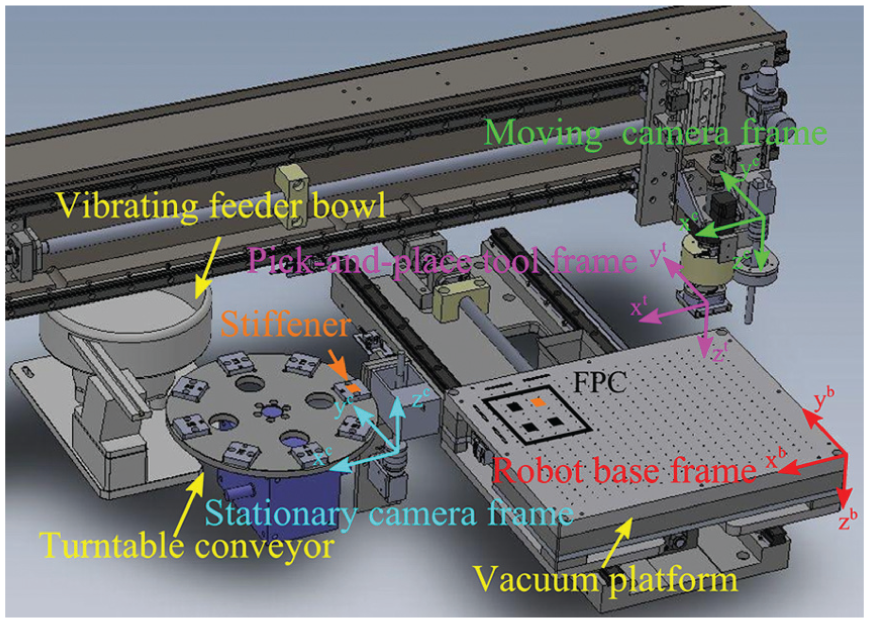
Structure of ASB system.
The ASB system proposed in this article adopts GTS-800-PV(G)-PCI series motion controller to control the MINAS A5-series AC Servo Motor & Driver produced by Panasonic. The software is developed using C-sharp (C#); the programs associated with camera calibration and image processing are accomplished using Halcon software; 27 this part of the code is replaced with open source code (OpenCV) in the subsequent development.
In order to achieve high-speed, precision bonding in the ASB system, first, to ensure the accuracy and repeatability in positioning, the motion precision of the robot (e.g. rotation angle around the Z-axis) must reach a given standard. 28 Second, the camera calibration and hand–eye calibration must be implemented for the motion pathway calculation.
Camera calibration
Eliminating the errors in the vision system, such as camera distortion, requires a calibration board to estimate the nonlinear intrinsic and extrinsic parameters using a pinhole camera model; the coordinate of the target in the image frame
Hand–eye calibration
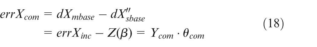
In the calculation of motion pathway,
Principles for the transformation of the stationary camera and the base
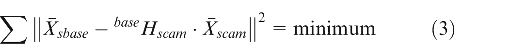
The transformation between stationary camera frame and robot base frame frames is calculated as given in equation (1)

In the calibration of the stationary camera, the rotation center of the pick-and-place tool (the origin of the tool coordinate system) is selected as the fiducial mark, and the coordinates of the fiducial mark in two coordinate systems (

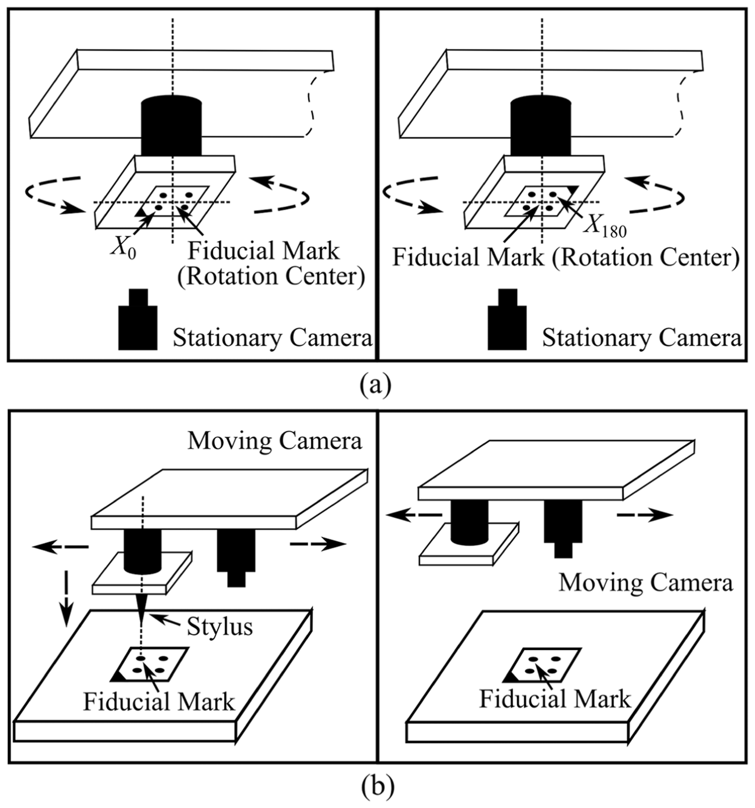
Schematics of hand–eye calibration: (a) stationary camera and (b) moving camera.
In this manner, the
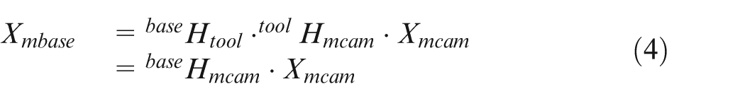
Principles for the transformation of the coordinate systems of the moving camera and base
Equation (4) illustrates the relative positions and orientations of the moving camera frame and base frame, which changes with the location of the pick-and-place tool. However, the relative positions and orientations of the tool frame and the moving camera frame do not change. Therefore,
First, as shown in Figure 3(b), the calibration board is fixed to the working plane, and the central dot of the calibration board is set as the fiducial mark. The robot is manually operated to move the tip of the stylus mounted on the end-effector to the center of the fiducial mark, to measure the coordinate of the fiducial mark in robot base frame (
In summary, this section illustrated the process of obtaining the homogeneous coordinate transformation
Error analysis and compensation in ASB system
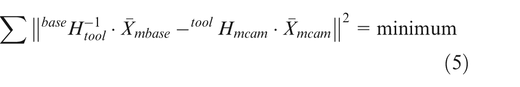
Placement error in the ASB originates primarily from the errors associated with hand–eye calibration and the motions of the pick-and-place tool. With regard to the former, the coordinates of the fiducial mark in the base frame (
Incomplete error model based on hand–eye calibration error
In the calculation of the motion pathway, homogeneous coordinates’ transformation is used to obtain the relationship between the location of the stiffener and the rotation angle of the pick-and-place tool. Then the stationary camera provides the initial location of the stiffener (
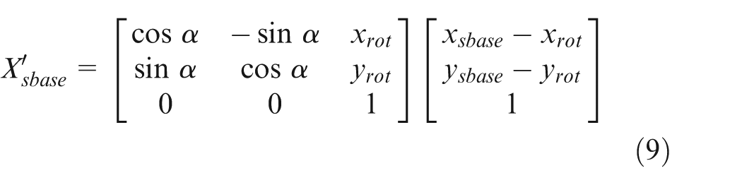
The moving camera provides the stiffener placement location

Hand–eye calibration can result in an offset in the origin of multiple coordinate systems. If each error term caused by the offset is considered as a fixed value (e.g.
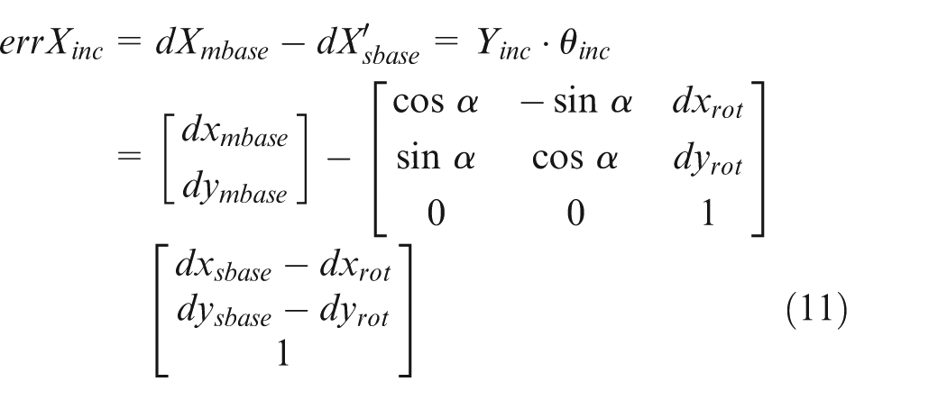
Using the placement errors (

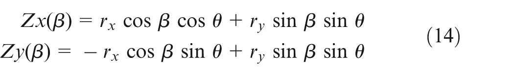
Complete error model based on errors from calibration and tool motion
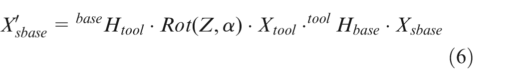
The incomplete error model only considers the error caused by hand–eye calibration. As shown in Figure 4, the rotation center associated with the pick-and-place tool changes with
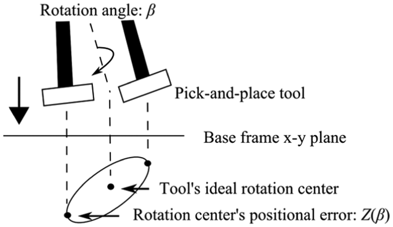
Error associated with pick-and-place tool.
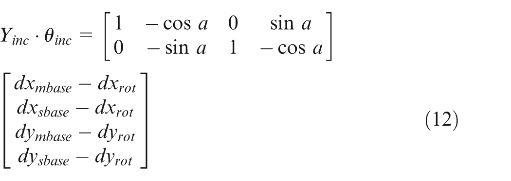
As a result, the pick-and-place tool creates new errors in
Equation (16) reveals that the resulting new placement error is

In summary, the final placement errors caused by hand–eye calibration and motions of the pick-and-place tool are

Experiment results
To compensate the placement error of the ASB system, the incomplete and complete error model is developed, and the compensation results are compared between the two models. The flowchart of the experiment procedure is shown in Figure 5.
Flowchart of the experiment procedure.
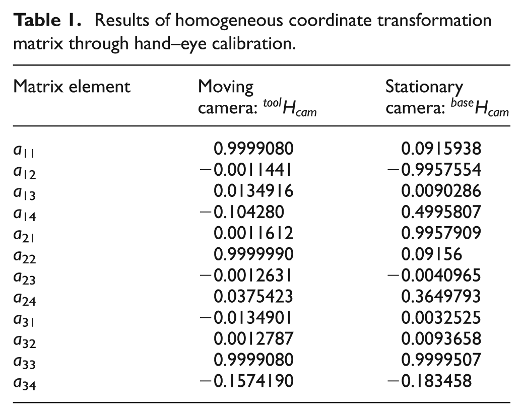
Hand–eye calibration results of ASB
A calibration board was used to calibrate the moving camera and the stationary camera,
27
the calibration board is made from glass plate and its size is
Images taken by (a) moving camera and (b) stationary camera during hand–eye calibration.
Results of homogeneous coordinate transformation matrix through hand–eye calibration.
Development of system error model
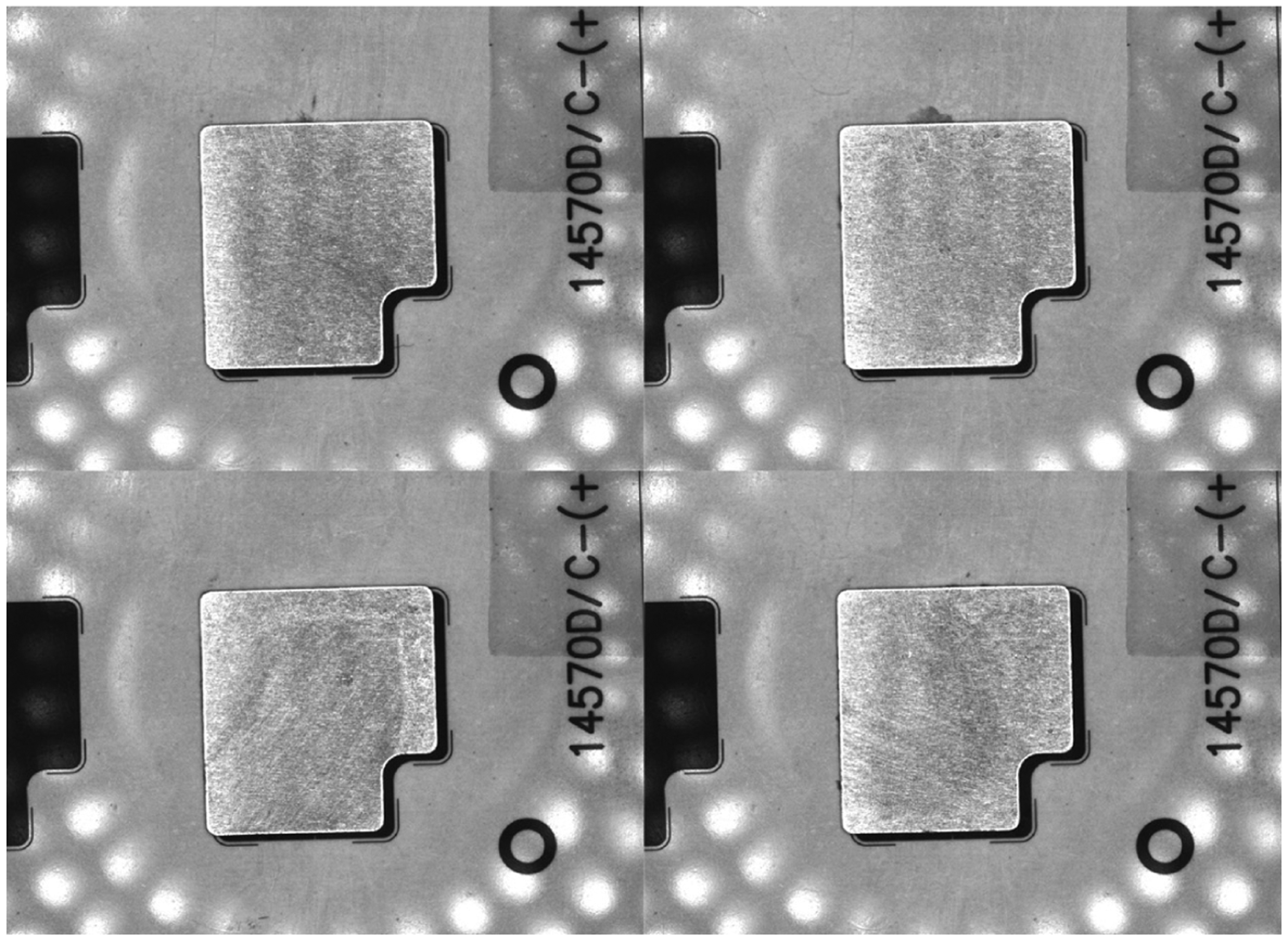
To obtain an accurate error model, the FPC is replaced with a film that is designed to high-precision patterns according to the shape of standard stiffeners, as shown in Figure 7(b). The stiffeners were mounted on the film, and the images of the mounted stiffeners were collected to derive the placement error and calculate the parameters of the error model.
Experiment images: (a) FPCASB, (b) film pieces used to replace the FPCs and (C) FPC products.
As the rotation angle of the stiffeners is related to the mechanical structure of the feeding component (e.g. a rectangular slot is used for feeding on the turntable), the rotation angle of the stiffeners during the mounting is approximately −90° and 0°. To derive the unique solution of equation (19) and increase the accuracy of the model parameters, the stiffeners are placed manually on the turntable to approximately −90°, 0°, 90°, and 180°, which caused the stiffeners to be picked up (by the pick-and-place tool) at various angles, as shown in Figure 8. This was repeated 20 times for each angle, which resulted in a total of 80 records pertaining to the rotation angle required for each stiffener (

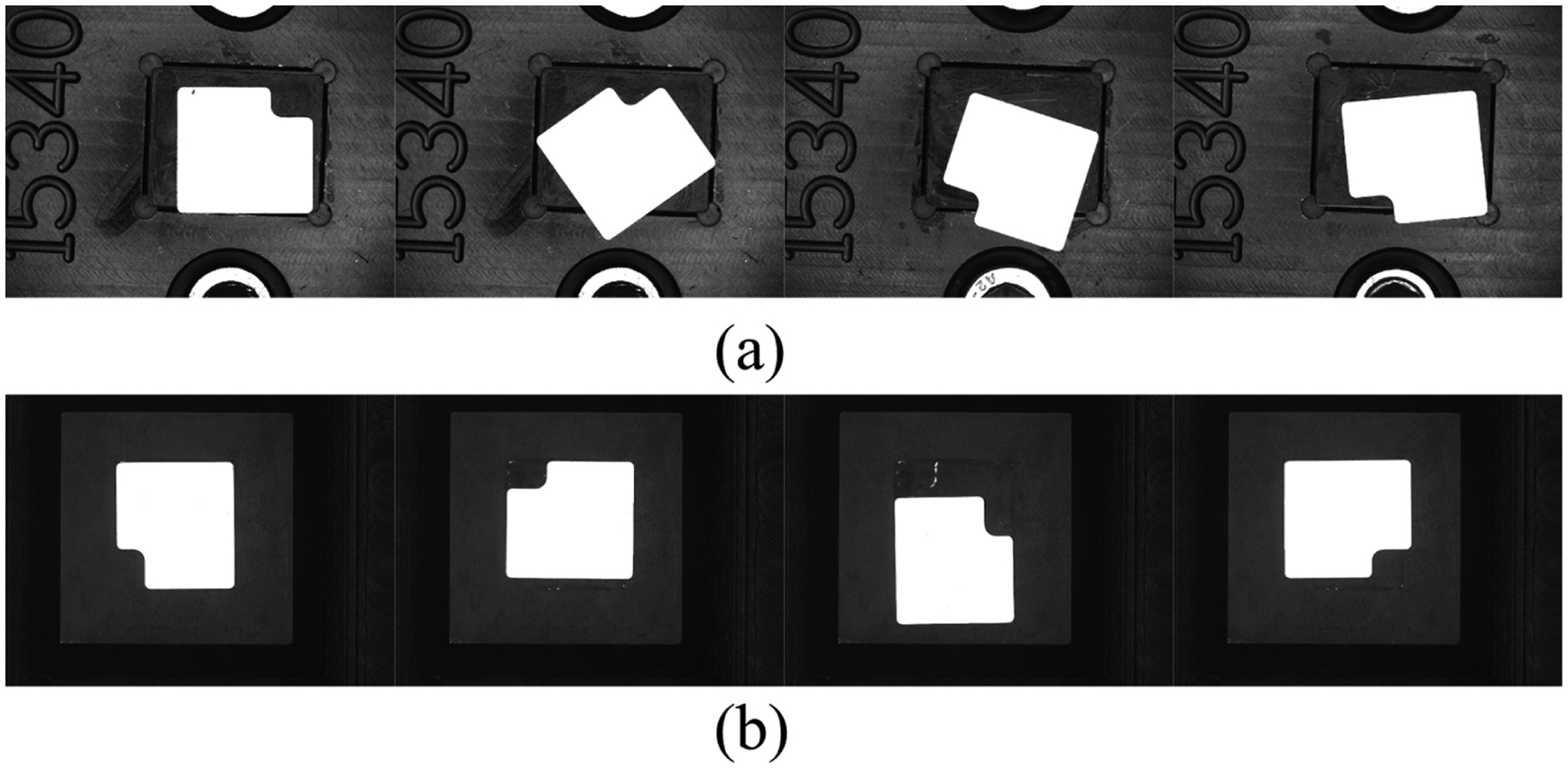
Stiffeners held at different angles in the initial location: (a) images on turntable and (b) images on pick-and-place tool.
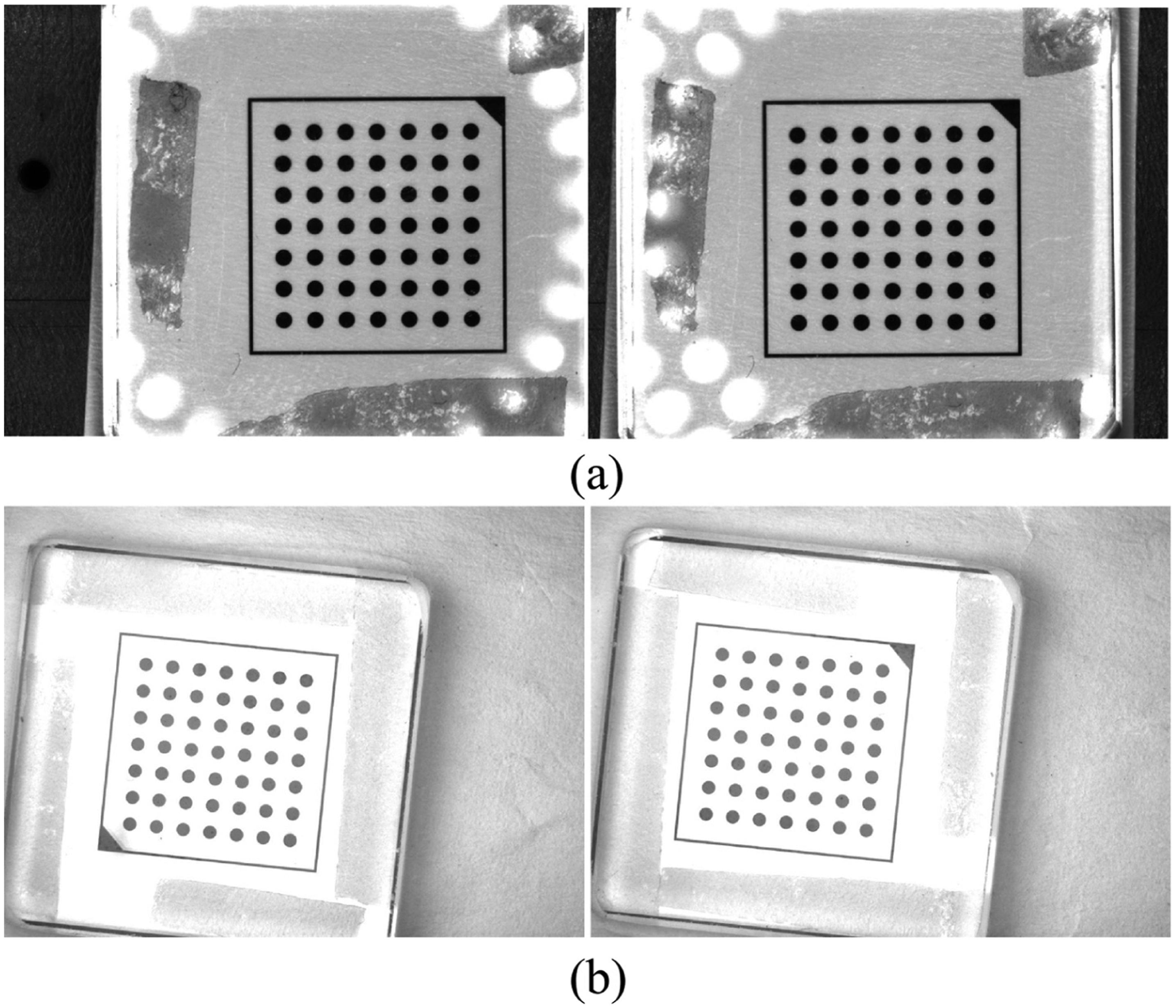
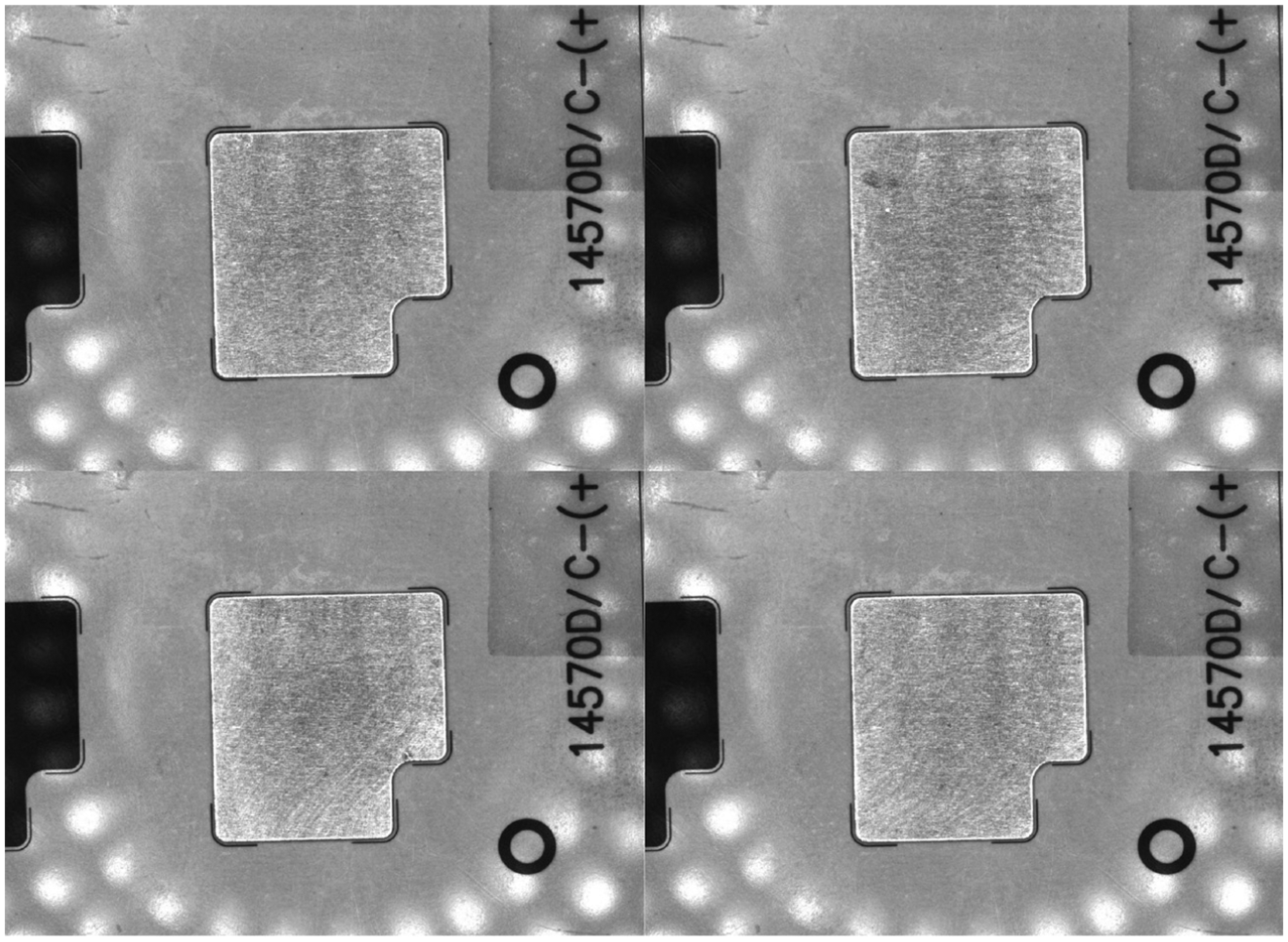
Figure 9 shows the images of the stiffeners mounted at the same location. The offset between the top centers of the stiffeners (

Images of stiffeners mounted at the same location without error compensation.
As shown in Figures 10 and 11, different rotation angles can lead to different coupling situations, resulting in different values pertaining to placement error. The offset of the stiffeners in the X- and Y-directions was obvious, revealing the edges of the film pattern in the images. The placement errors were significant (exceeding 0.3 mm), far exceeding the precision threshold associated with mounting.
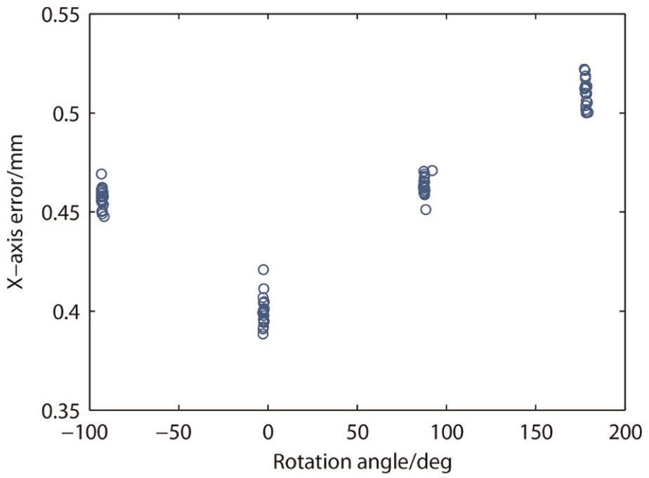
Placement error in X-direction without error compensation.
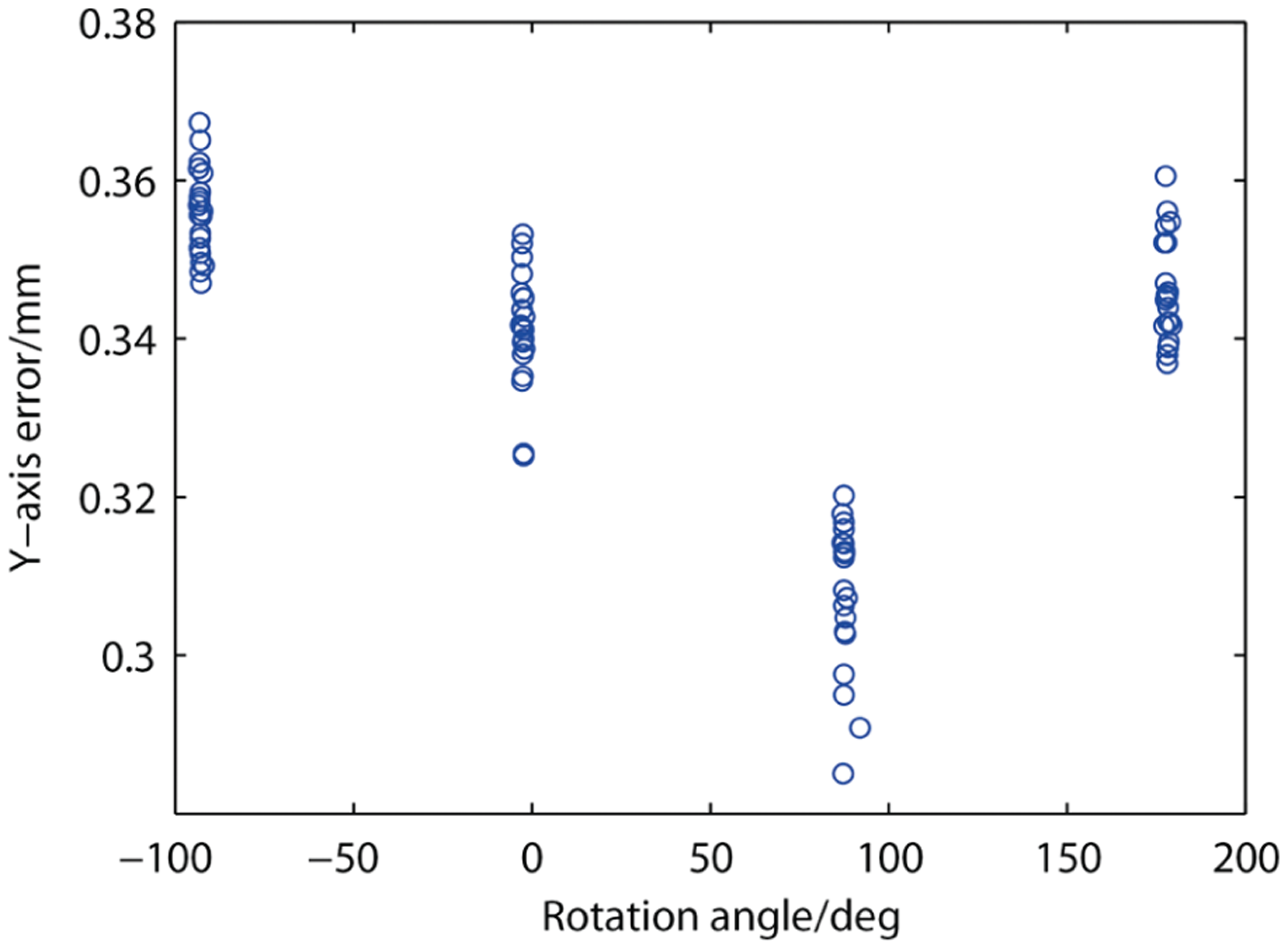
Placement error in Y-direction without error compensation.
To contrast the effects of error compensation, the complete and incomplete error models are developed using the
Error model parameters.
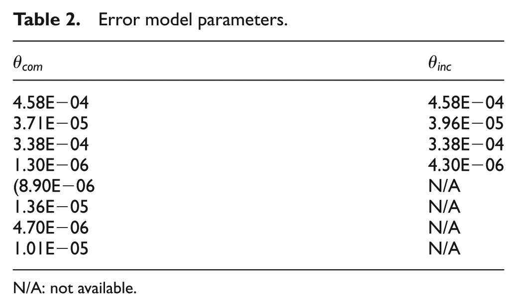
N/A: not available.
Results of error compensation
To provide a reasonable description of placement precision, a process capability index (CPK) is employed to serve as a standard,
30
as given in equation (22), where sigma denotes the root mean square error (RMSE),
Compensation with incomplete error model
Using the same placement location, the stiffeners are rotated to four directions 80 times. An incomplete error model (without consideration for the errors in tool motions) is used for error compensation. The images of the mounted stiffeners and placement error results are presented in Figures 12–15. As can be seen, after compensation, the top centers of the stiffeners and the film patterns are almost identical, and the effects of error compensation are obvious. A comparison with the mounting results without this compensation shows that the errors after compensation were decreased by an order of magnitude. Based on the value of 3sigma in equation (22), the mounting precision of the system in the X- and Y-directions is (0.043 mm, 0.049 mm), noted as ±0.049 mm at 3sigma.
Images of stiffeners mounted at the same location with compensation using incomplete error model.
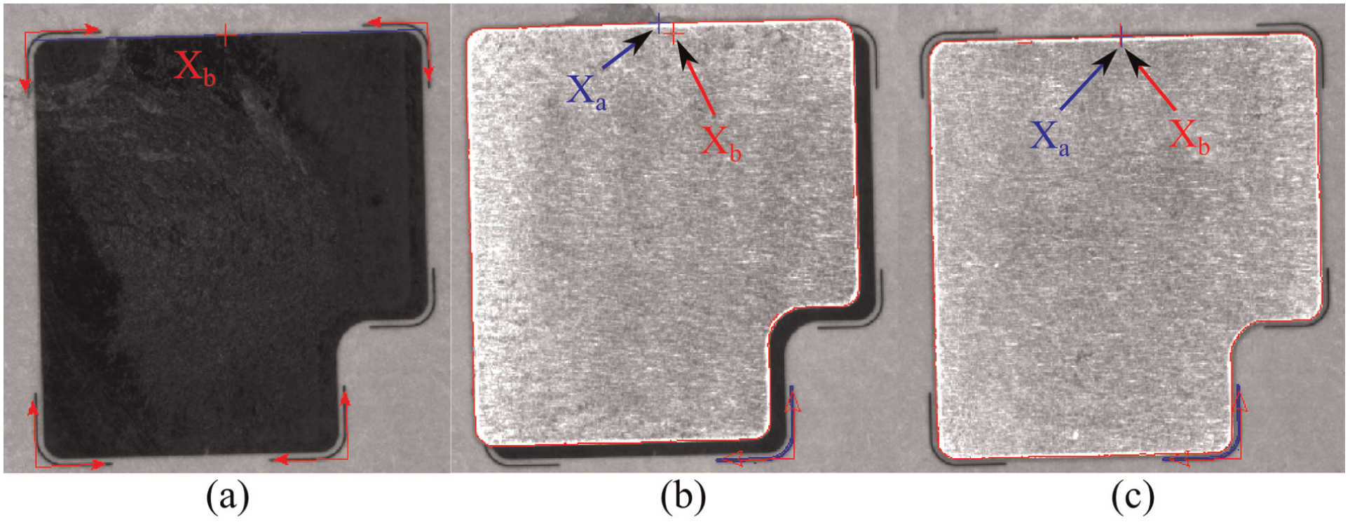
(a) Film pattern and mounted stiffener images (b) before and (c) after compensation using incomplete error model.
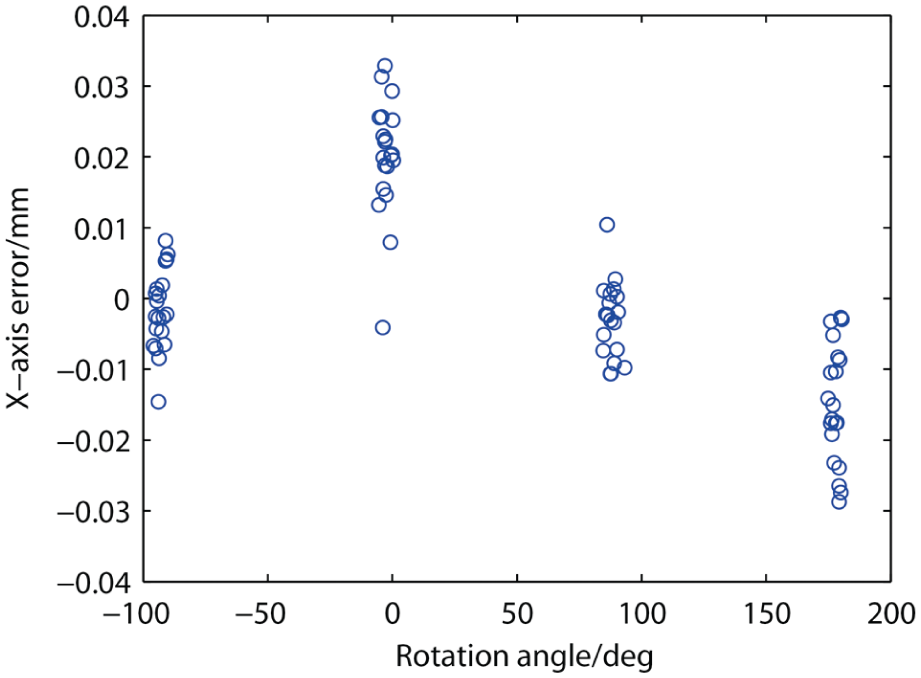
Placement error in X-direction with compensation using incomplete error model.
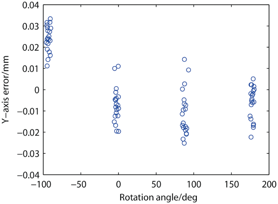
Placement error in Y-direction with compensation using incomplete error model.
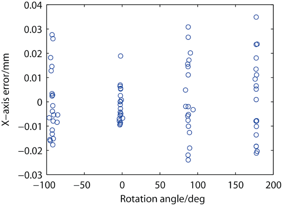
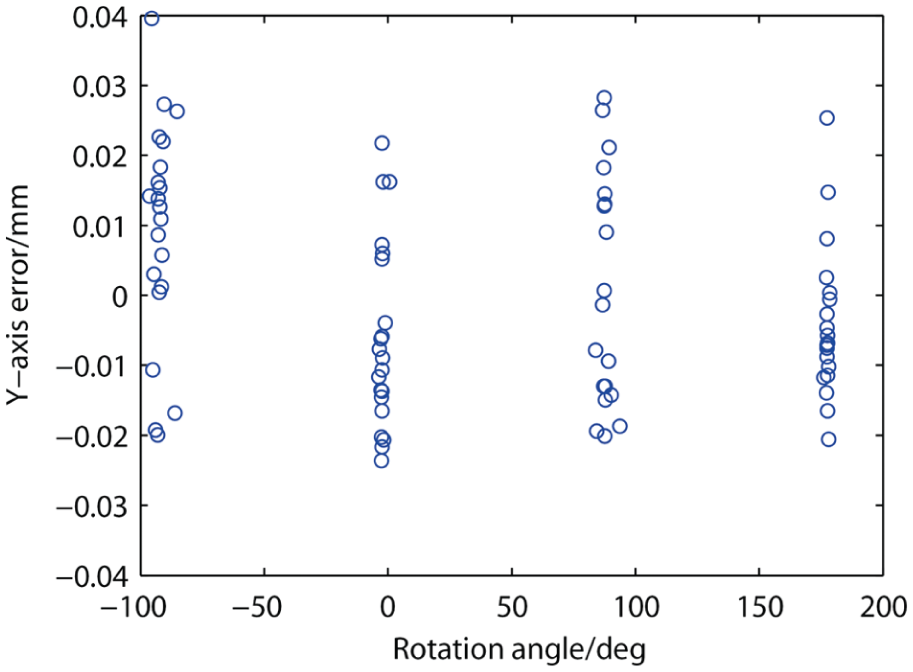
Compensation with complete error model
Using a complete error model, the experiment is repeated, the placement results of which are presented in Figures 16 and 17. The error after compensation with complete model is more evenly distributed and less affected by the rotation angle; comparing with the incomplete model, the complete model enables to eliminate the errors from motion associated with the pick-and-place tool. The mounting precision of the system became (0.032 mm, 0.038 mm), noted as ±0.038 mm at 3sigma. Based on the mounting precision after compensation with the two models, this comparison shows that using complete error model results in further 28% reduction in placement error.
Placement error in X-direction with compensation using complete error model.
Placement error in Y-direction with compensation using complete error model.
With regard to the placement error caused by pick-and-place tool motion, the complete model not only considers the affect of the tool rotation but also considers the strong downward force after tool pressing down which can increase positional errors of the rotation center of pick-and-place tool. Through rotating the tool every 30° without pressing down and capturing the images using the stationary camera, the error trajectories of the rotation center are obtained with a similar method of deriving
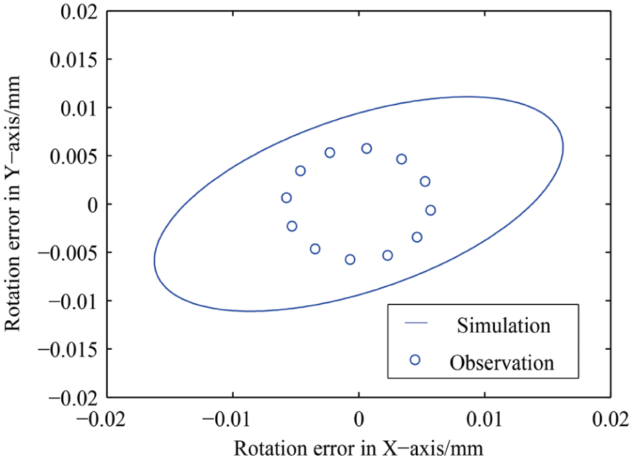
Error trajectories of pick-and-place tool associated with rotating and pressing down.
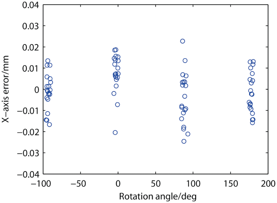
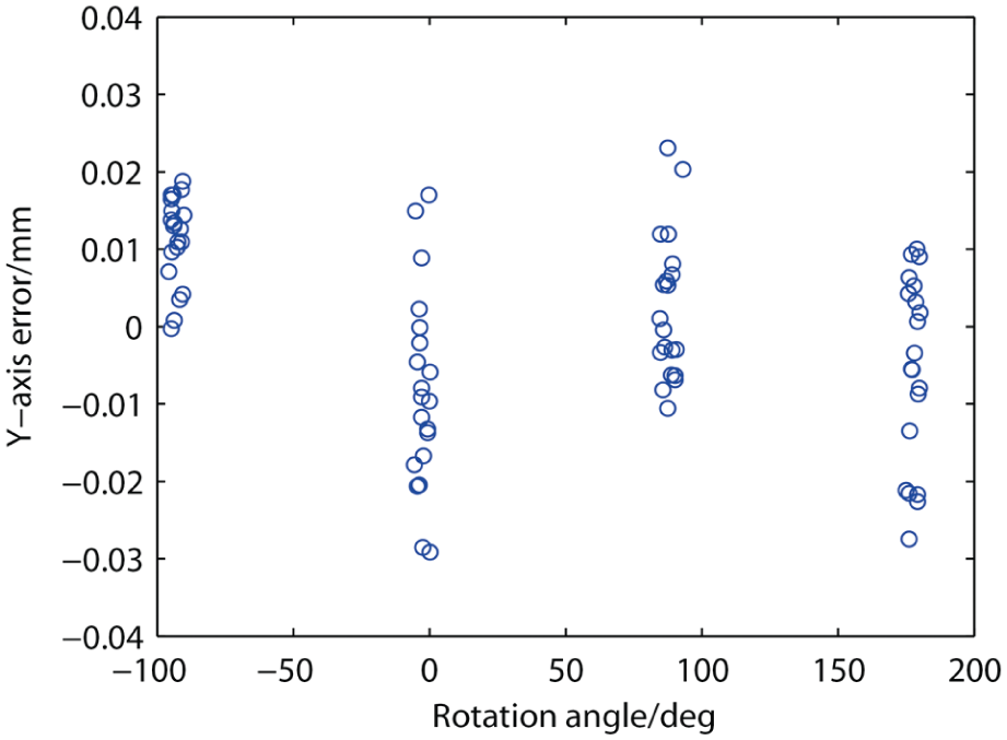
Compensation in the entire workspace
To determine the mounting precision of the system throughout the entire work area, 80 stiffeners are mounted onto multiple placement locations and used the complete error model for compensation. The results are presented in Figures 19–21. As can be seen, an increase in the work area led to an increase in the placement error caused by motions in the mechanism, becoming (0.041 mm, 0.046 mm), noted as ±0.046 mm at 3sigma. In actual FPC production, the SL of stiffener mounting generally ranges from 0.1 to 0.15 mm, and the CPK of the qualifying mounting equipment must be greater than or equal to 1.33. This study adopted a higher precision requirement (SL = 0.1 mm), as shown in Figure 9(c). The calculations of mounting precision throughout the entire work area of the ASB system in this study presented a CPK of 2.19, clearly demonstrating the effectiveness of the proposed system. Several tests indicated that the finished products also fulfilled precision requirements.
Stiffeners mounted at different locations.
Placement error in X-direction over the entire work area.
Placement error in Y-direction over the entire work area.
Conclusion
The experiment results show that error coupling and placement error vary with the rotation angle of the stiffener; the errors were exceeding 0.3 mm before compensation. Therefore, an error model is used to compensate for placement error in the system, thereby reducing placement error by an order of magnitude. The complete error model considers the errors caused by motions associated with the pick-and-place tool, further reducing the error by 28%. As for the errors in the rotation center of the pick-and-place tool, the simulation by error model and direct observation presented different results, demonstrating that the error model takes into account the influence of downward pressing motion associated with the tool. For the same mounting location, the mounting precision of the system is ±0.038 mm at 3sigma, whereas the precision of the system in the entire work area is ±0.046 mm at 3sigma. For FPC products with an SL of 0.1 mm, the CPK of the FPCASB in this study is 2.19, which indicates good mounting capabilities, capable of fully satisfying the high-precision requirements of FPC stiffener bonding. The approach used in this study is suitable for other types of workpiece that vary randomly in pick-and-place angle. This method is also applicable to applications in visually guided high-precision pick-and-place systems with 4 DOFs. Furthermore, based on the proposed error model, the effect of temperature on the placement error in the ASB system will be considered for future work.
Footnotes
Appendix 1
Declaration of conflicting interests
The author(s) declared no potential conflicts of interest with respect to the research, authorship, and/or publication of this article.
Funding
The author(s) disclosed receipt of the following financial support for the research and/or authorship of this article: This work was funded by National Nature Science Foundation of China (No. 61205004).