
Abstract
In this study, the two geometry tools, including straight cylindrical pin and upward conical pin, are used to create channel in monolithic plate of Al 5083 alloy using the modified friction stir channeling technique. The channeling process was done under different directions including linear and non-linear channeling paths. Using upward conical pin caused easy channeling under non-linear paths, increase in height and hydraulic diameter of channel, and improvement in channel structure. As a result, in modified friction stir channeling technique using both tools, the shape of channels was stable and constant along the different channeling paths. However, the channel size was changed along the different paths. Along the vertical and straight paths, the characteristics of channel were stable and constant during the channeling process. Existing results were also achieved along the curve direction when the advancing side was along the inner curve. Nevertheless, when the advancing side was along the outer curve, the values of channel characteristics were varying at the various locations of the curve path. The stop-action technique and observations on the cross section of channels were utilized to explore the variations of channels and the channeling mechanisms along different paths. It was found that the variations of channel properties were because of the location of the displacement of shear layers along curve and the amount of extracted material by tool pin along the curve paths.
Keywords
Introduction
During the friction stir (FS) processes such as friction stir welding (FSW) and friction stir processing (FSP), the volumetric defect can occur due to wrong process parameters, which is named wormhole defect. 1 Friction stir channeling (FSC) is a simple technique for creating continuous and integrated channel in monolithic plates based on wormhole defect. 2
Threaded tool pin is utilized by Balasubramanian et al. 3 for the creation of mini channel in commercial Al 6061 alloy. They found out that the channel created along the curve paths has different shapes. Besides, at the some points of channeling line, the changing area of the channel is approximately 50%. Thus, the characteristics of channel are not constant for each channel in previous version of FSC. These phenomena can limit the applications and competency of channel. They reported that a clearance between shoulder and workpiece should be used to deposit material. The area of channel was equal to the area of material deposited underneath the shoulder. Therefore, material deposition controls the shape, size, and integration of channels. In FSC technique, deposited material underneath the shoulder at the channeling line is not uniform.4,5 Therefore, the channel properties such as shape, area, and hydraulic diameter of channel cannot be stable along the channeling line. This phenomenon shows that material flow varies in different locations of the channeling line in FSC using threaded tool pin.
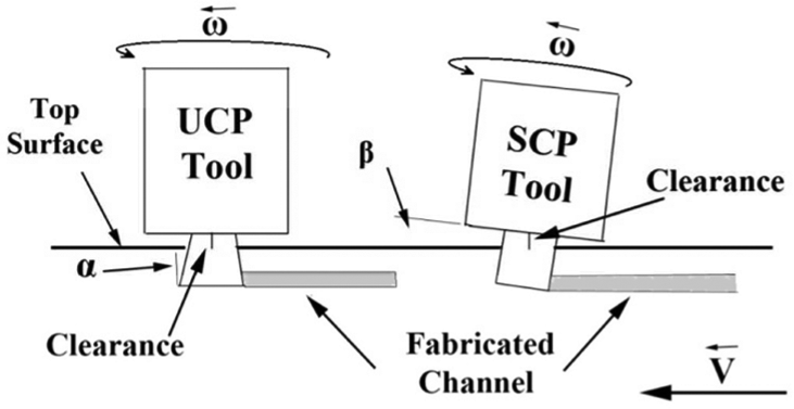
Modified friction stir channeling (MFSC) is a newest technique to create FS channels. 6 Both FSC and MFSC are the techniques used to produce internal channel in metal component based on FS process rules. These techniques are different in tool geometry and tool setup. The methods for extracting material are also different. The FSC uses the threads on tool pin to extract material (deposited material) from process zone. However, the MFSC uses the tilted pin and the plow force in front of tool pin to extract material from around tool pin to underneath the shoulder. The two techniques are illustrated in Figure 1. Unstable channel properties (shape, area, and hydraulic diameter) are solved in the length of channel by MFSC technique, which is the negative aspect of the FSC.
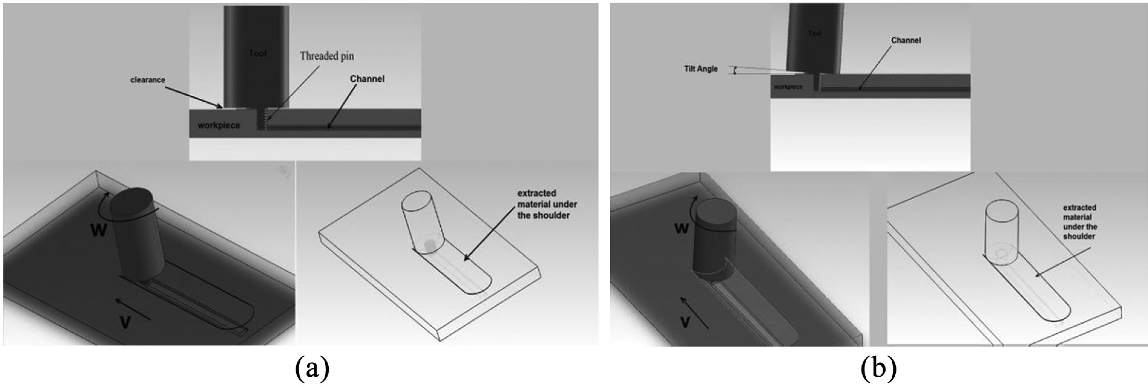
Techniques to fabricate friction stir channel: (a) friction stir channeling (FSC) and (b) modified friction stir channeling (MFSC).
Material flow in FS processes is attributed to the tool geometry and process parameters. 7 There are different innovative techniques for studying material flow around the tool pin, 8 such as applied dissimilar base metal. This technique is the specified method for FSW, where the base material can be dissimilar. Inserting marker technique (IMT) is used by Lorrain et al. 9 which investigated reflecting marker material on the nugget zone. One base metal with embedded tracers 10 or bush Cu on the surface to be welded 11 also is the useful technique for the investigation of material flow paths around the tool pin. Broken pin technique 12 is a more performing method to investigate shear layers of material on tool pin body for each revolution of tool. In stop-action technique, 13 the FS machine stops suddenly and the material flow around tool pin is studied.
Rashidi et al. 14 investigated material flow and channel formation in MFSC technique using weakened tool pin method. They reported that MFSC channels are formed by extraction of material into the shoulder cavity at the front of tool pin using tilted pin. The area of extracted material is equal to the channel area and the area of internal groove on the channel roof in advancing side (AS). Tool rotary motion moves the extracted material toward the back of tool. Traverse motion, which is effective on increasing forging force, forges material to the internal groove. The remained material are deposited to AS and retreating side (RS) as flash. The flash area was equal to the area of channel and the area of remained internal groove. Therefore, a geometric flaw can be formed, which is effective on channel shape and integration of channel roof. This defect is named as the “step” and can occur when the material flow on channel roof is insufficient. Step is known as a defect because (1) it deforms the shape of channel and shifts it to a formless shape, and (2) it reduces the integration of channel roof by formation of internal groove on channel roof.
The channels created using MFSC can be applied to produce plate-fin compact heat exchanger. Plate-fin heat exchangers (PFHEs) are a form of compact heat exchanger consisting of a stack of alternate flat plates called “parting sheets” and fin corrugations, brazed together as a block. The PFHE is limited in the application to relatively clean streams, because of its small flow passages. 15 Salient features of PFHE discussed by Ward 16 include low-pressure applications (lower than 10 bar), gas-to-gas applications, and low cryogenic operating temperatures in Al PFHE. The PFHE is not necessarily cheaper for a given heat duty than other forms of heat exchangers, because the method used for constructing PFHEs is complex and energy-intensive. 17 Although passages of triangular and rectangular cross sections are more common, any desired shape can be given to the fins, considering only manufacturing constraints. Straight fins in triangular arrangement can be manufactured at high speeds and hence are less expensive than rectangular fins. But generally, they are structurally weaker than rectangular fins for the same passage size and fin thickness. They also have lower heat transfer performance compared to rectangular fins. 15 Aluminum is preferred for cryogenic duties because of its relatively high thermal conductivity, strength at low temperatures, and low cost. The Al alloys 3003, 5154, 5083, 5086, and 5454 are used to fabricate the PFHE. 16
Kuppan 15 explained that one of the main effective parameters in heat exchangers is the hydraulic diameter of the channel. The hydraulic diameter is a term that is commonly used for fluid flow in non-circular tubes and can be obtained by equation (1)
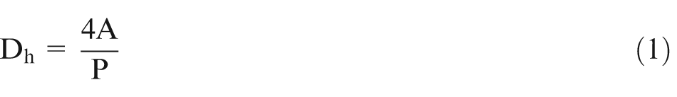
where Dh is the hydraulic diameter, A is the channel area, and P is the channel perimeter.
Due to previous study on FSW and FSP, the variations of tool profile or tool setup change the physical properties of volumetric defects (shape, size, location) in process zone.18,19 Therefore, the channel formations in FSC and MFSC also are different due to different tool profile and setup. This article extensively aims to present the channeling mechanism and characteristics of FS channel along the non-linear paths in MFSC technique. Moreover, influence of tool profile on the channel formation along the linear and non-linear channeling also is discussed. Understanding the differences of the two tools on channel is carried out by stop-action technique, as a technique to study the material flow. On the other hand, a new geometry tool pin, for the first time, was introduced in this article.
Design and experiments
A 10-mm-thick plate of Al 5083 alloy is used as workpiece. Two workpieces with 300 × 300 mm2 and 300 × 150 mm2 are applied as specimens to create channel at non-linear directions. Material of tool is H13, which has been hardened up to 51 HRC. Two tool pin profiles are used in which one of them is non-threaded upward conical pin (UCP) with (2α = 6°) conic angle as a new tool, and other tool pin profile is non-threaded straight cylindrical pin (SCP) as an old tool.
In UCP tool of MFSC setup, no tilt angle between tool and workpiece is used, while the old version of MFSC is carried out using 3° tilt angle (β = 3°). The two applied tools’ profile and their dimensions are indicated in Table 1. Concave shoulder with 5° is used to embay extracted material under the shoulder. Investigated parameters, which are used to fabricate channels by new tool, are shown in Table 2.
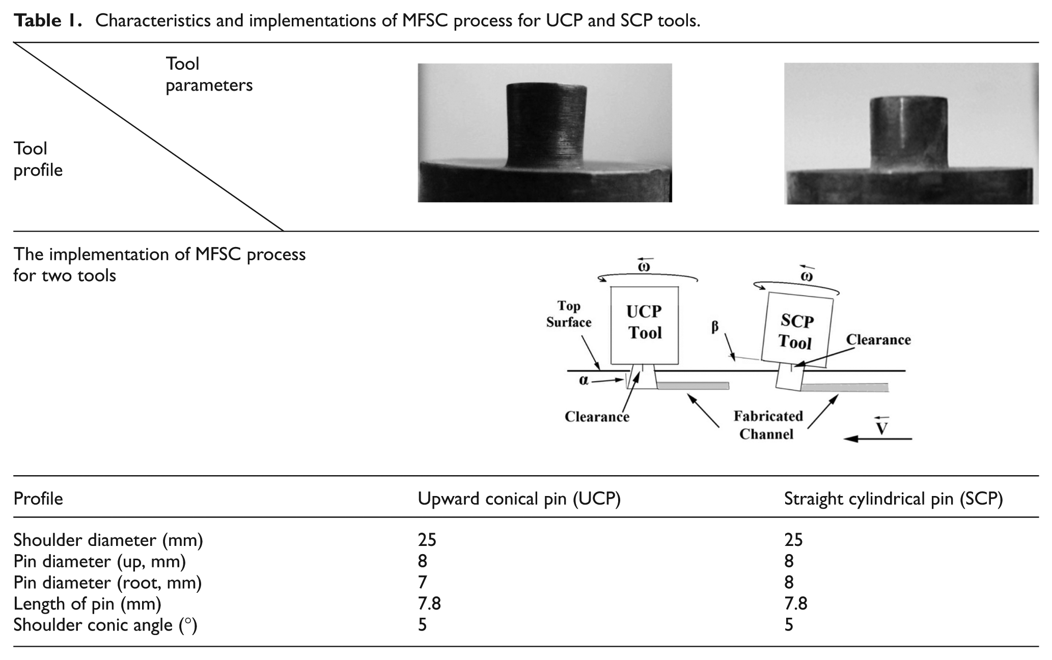
Characteristics and implementations of MFSC process for UCP and SCP tools.
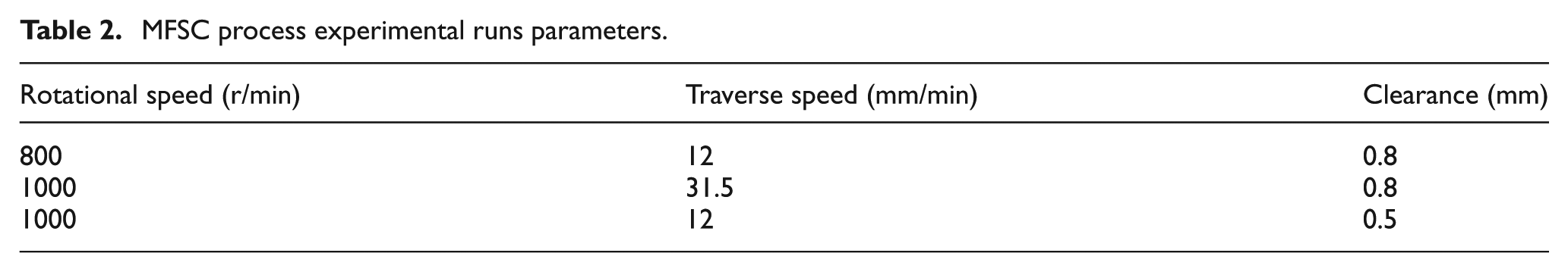
MFSC process experimental runs parameters.
The cross section of channel at the various locations in curve directions is provided by wire cutting. The critical points of direction are shown in Figure 2(a) and (b) in which the clamping and orthogonal directions are passed by tool during channeling process.
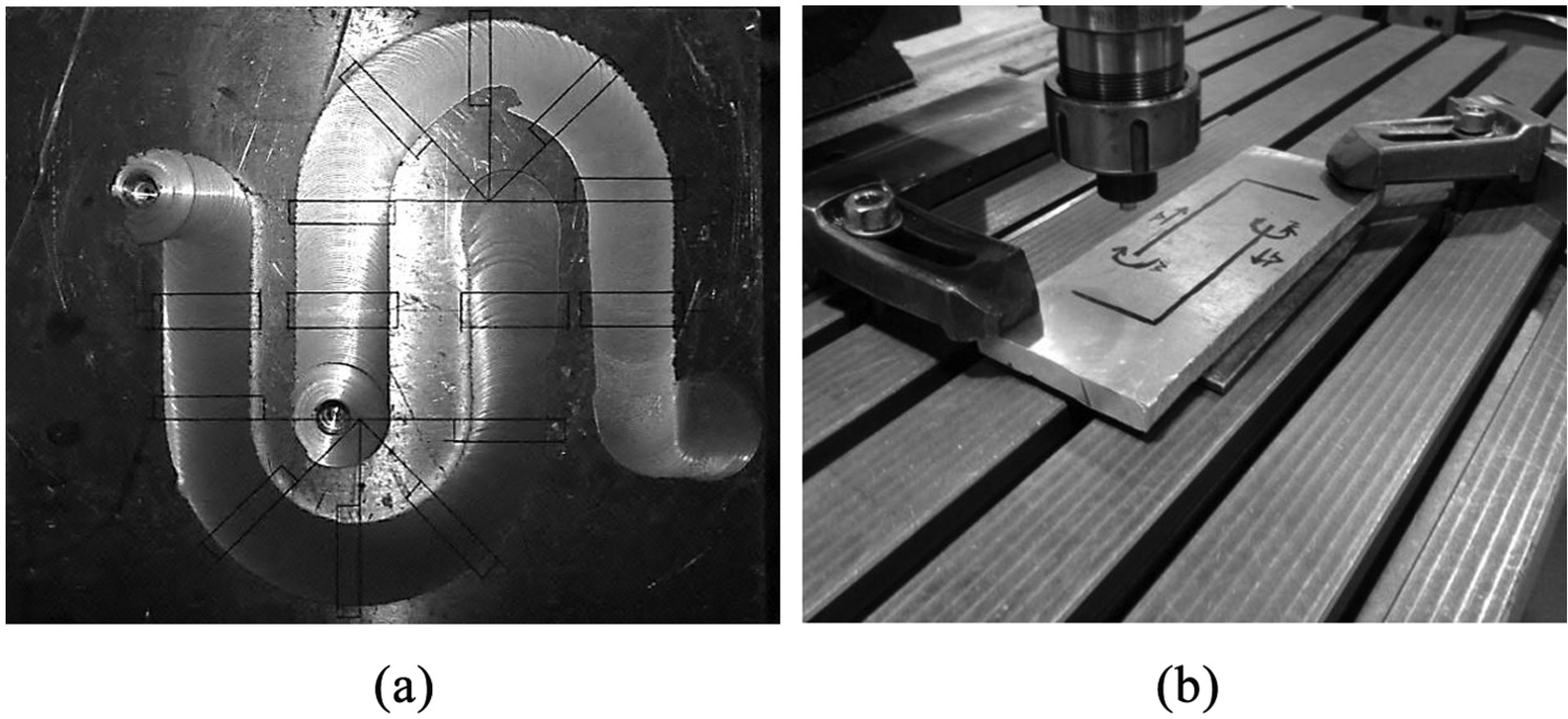
(a) Selected location for cutting by wire cut along the curve paths and (b) setup and directions in orthogonal line test.
For investigated channel properties at the orthogonal direction, the material in channel roof is removed by milling process. In order to investigate channel properties, a 9-MP digital camera is used to provide macrographs from cross section of the samples. Moreover, properties of channels (area and perimeter) are obtained by means of image processing techniques using “Image J” software.
Material flow is studied using stop-action tool technique on both tools of MFSC under similar process conditions. The keyholes are created, and cross sections of channels are explored for both tools to understand the differences of material flow between two tools.
Results
Influence of tool geometry on channel formation
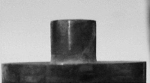
The channels made at similar process parameters using two tools of MFSC are shown in Figure 3. According to Figure 3 for both tools, deposited material underneath the shoulder remains constant along the channeling line. Therefore, the material flow during channeling process is stable and constant for both tools of MFSC. This phenomenon demonstrates that the properties of channel remain constant along the channel. It is evident that three great differences exist between two shapes of channels at the cross-sectional view. First, with SCP tool, the big “step” creates in AS and changes the channel shape to a formless shape. Due to Figure 3(b), this imperfection is disappeared using UCP tool and the structure of the channel is improved. Second, investigation of channel height in Figure 3 shows that the UCP tool increases the minimum channel height (32%) at the same process parameters. Increasing the height of the channel is attributed to the reduction in falling material into the channel cavity. Third, study of channel properties including area and hydraulic diameter shows that the area of channel for both channels is nearly 18 mm2. The perimeter of the channel experienced a 5-mm reduction using UCP tool because of the improvement in the channel structure. Therefore, the hydraulic diameter of the channel according to equation (1) increases from 2.90 to 3.50 mm.
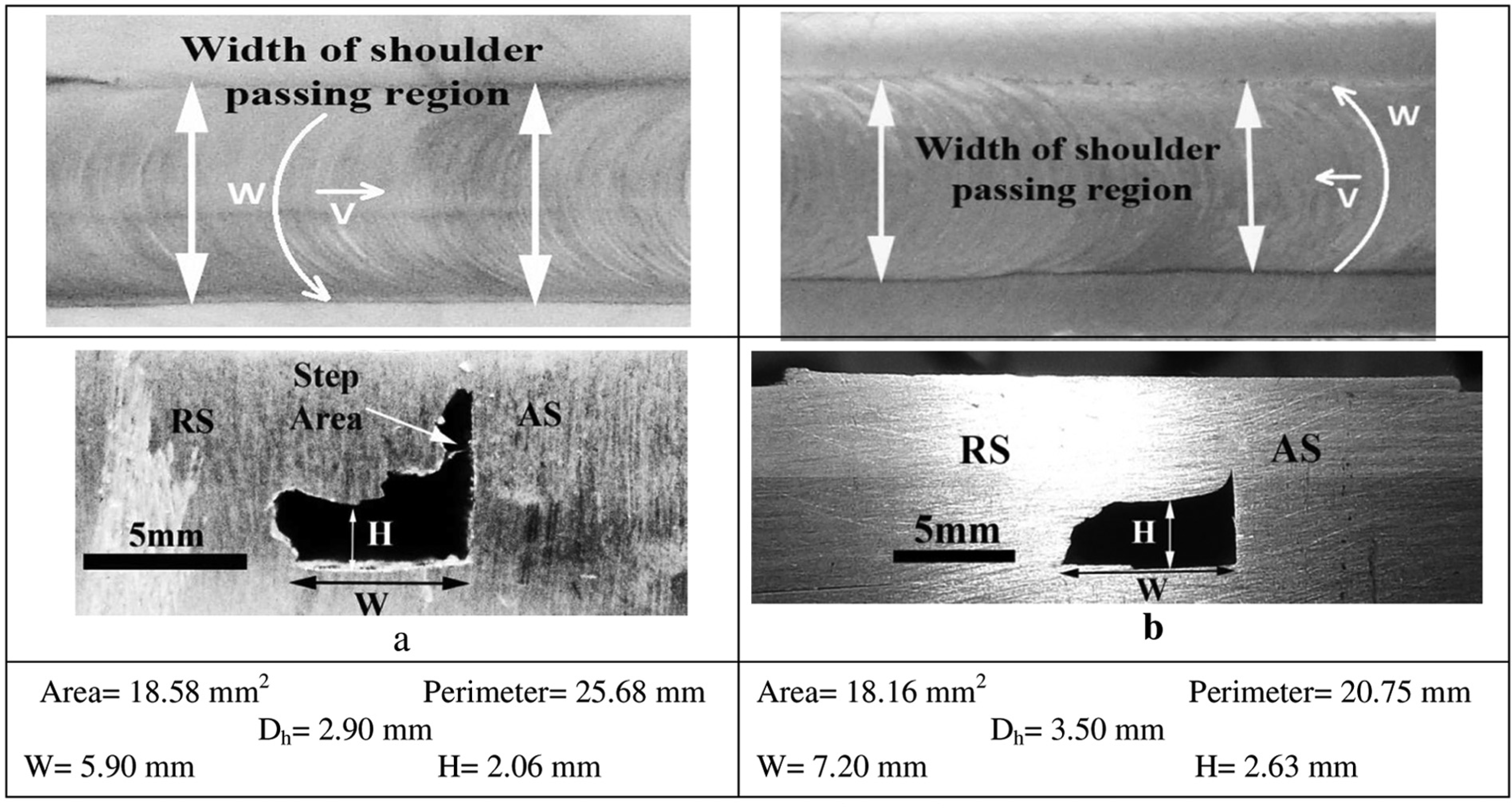
Top surface of process zone and cross section of fabricated channel under 1000 r/min, 31.5 mm/min and 0.8 mm clearance using (a) SCP tool and (b) UCP tool.
Formation of channel along non-linear directions
The main goal of MFSC technique is the creation of mini channels to be used in compact heat exchangers. These exchangers are characterized based on their values of the surface area density. The process must be able to generate continuous channels along different profiles in order to have an efficient compact heat exchanger being developed by MFSC. The characterization of channel, which is created along a linear path, is discussed in previous sections. This section studies the characterization of channel, which is created along the curvature.
Serpentine is one of the most usual profiles in heat exchange design with high applicability. 20 Serpentine profile is selected to maximize the surface area density of a heat exchanger and improves its performance. It is so difficult to create a serpentine passage in exchangers, and generally, there is a high pressure loss in these profiles because of its curvature. 21
The implementations of MFSC process for two tools are illustrated in Table 1. According to Table 1, the tilt angle is used to extract material in front of tool (leading edge). So, the SCP tool cannot produce simply the channel in non-linear direction (curve and orthogonal) because the center axial of the SCP tool is not vertical to the surface of the workpiece. However, this case is provided using the UCP tool geometry. Thus, the MFSC using the UCP tool can develop channels with more speed along the serpentine profiles because of the straightforwardness of the process. Channels are developed along the curved paths in order to study the continuity of FS channels. The parameters of processing and rotational directions of the tool are kept the same for the two operations, while the traverse direction of the tool is altered. This process is done in order to deviate the position of AS according to the traverse path during the channeling process.
Figure 4 shows the cross sections of channels created along the direction (D1) where AS is along the inner curve. Also, the cross sections of channels along D2 where AS is along the outer curve are illustrated in Figure 4. According to Figure 4, the shapes of channel along both curvature lines are stable and closer to trapezoid. Also, channel created along the two curves shows that the channel is continuous and no portions of the channel are blocked by material. So in MFSC, continuity and integration of channel is not dependent on AS unlike the FSC. 3
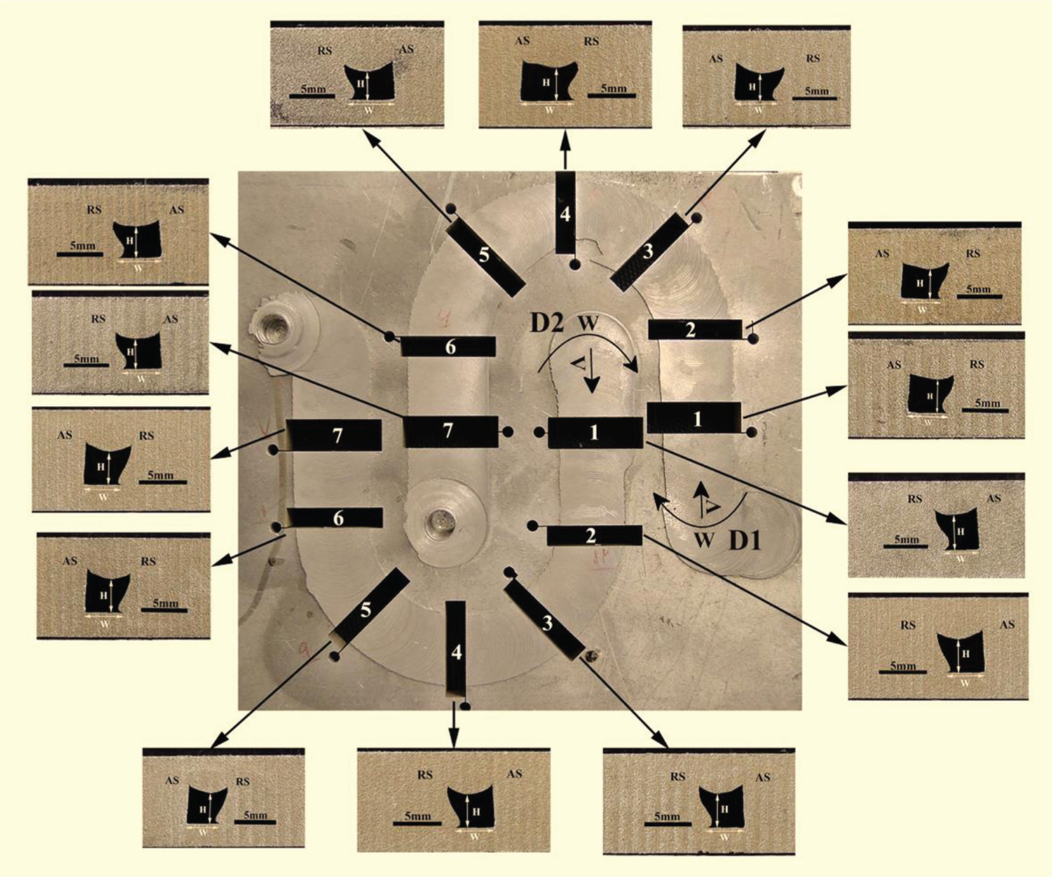
Cross sections of channels in different locations at the CW and CCW curve directions fabricated by UCP tool under 800 r/min, 12 mm/min and 0.8 mm clearance.
Table 3 presents the channel dimensions including minimum height (H) and bottom width (W) along the curve paths. When AS is along the inner curve (D1), the channel width increases in the first half of the curve (location from 2 to 4) and then decreases in the second half of the curve (location from 4 to 6). The values of the channel width variations are approximately 30%. However, the channel height has not experienced the high variations, and maximum change in the height of the channel is 7%. Maximum channel width value occurred at location 4 where the peak point of the curve occurred.
Variations of the channel characteristics along the curve paths, derived from Figure 5.
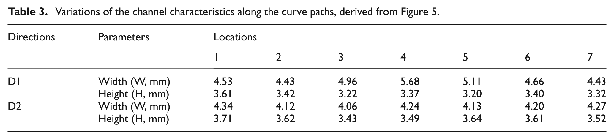
According to Table 3, along D2, the dimensions of channel are approximately constant and the variations of height and width of channel were 5% and 4%, respectively. It means that when the AS is along the outer curve, the MFSC technique can produce the channel with higher stable dimensions.
Diagrams in Figure 5(a), derived from Figure 4, indicate the areas of channels at the different positions of curve directions. According to Figure 5(a), on the D1 path where AS is the inner curve, the area of channel develops initially and then reduces. The area diagram for D1 is approximately symmetric with respect to point 4, and maximum area in this direction is 19.56 mm2. According to Figure 5(a), maximum variations of the areas along the D1 curve are about 22%.
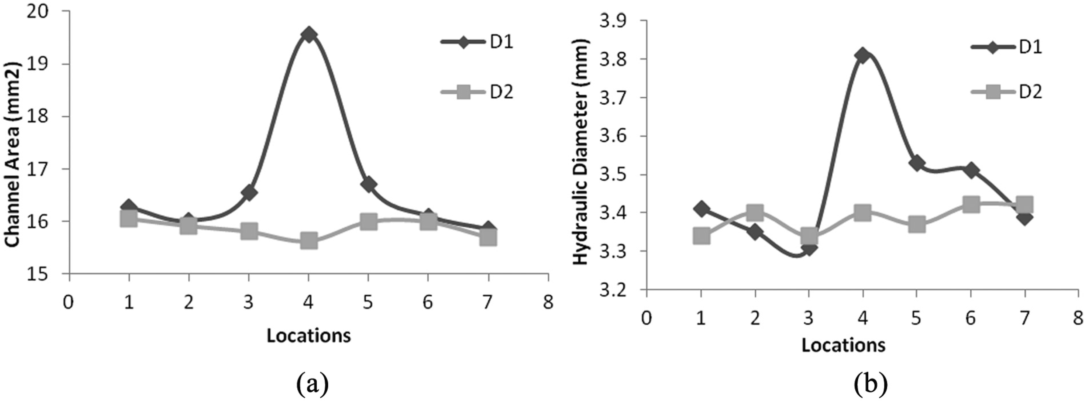
Figure 5(a) also shows that the channel area has a high stability along D2 compared to the D1. According to Figure 5(a), also it can be observed that the area of the channel has a slight reduction with a negligible variation (4%). The minimum area is 15.63 mm2 which is obtained at location 4.
Diagrams in Figure 5(b), derived from Figure 4, indicate the hydraulic diameters of channels at the different positions of curve directions. According to Figure 5(b), along the D1 curve where the AS is the inner curve, hydraulic diameter experiences an unstable behavior and the variations of hydraulic diameter are between 3.35 and 3.8 mm. However, along the D2 curve, the hydraulic diameter is approximately constant where AS is along the outer curve.
MFSC technique using UCP tool showed that the channels at any curve direction are open and continuous. As a result, it is also found that the channel with high stable properties (dimensions, area, and hydraulic diameter) can be produced when AS is along the outer curve.
The channel creation along the vertical directions has not been studied in the previous literatures of FSC. FS channel along the vertical path is important to develop the applicability of the channel. Figure 6 indicates the channel on orthogonal paths and differences between two routes. These differences are related to the position of AS which is determined by traverse and rotary directions.
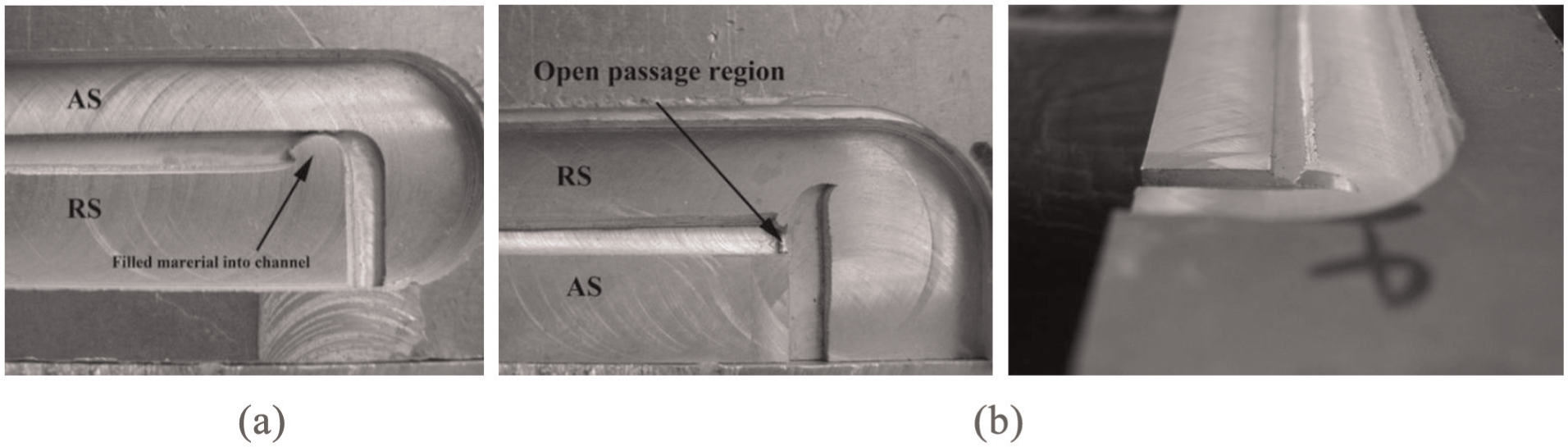
(a) Top view of channel (advancing side in outer route) and (b) top and front views of channel (advancing side in inner route), under 1000 r/min, 12 mm/min and 0.5 mm clearance.
When the AS is the outer route, according to Figure 6(a), the extruded material fills the channel and the channel is not continuous along the length. Front view of Figure 6(b) demonstrates that an open passage region exists when the AS is the inner route. Besides, due to Figure 6(a) and (b), the width of channel remains constant along the vertical direction.
Discussions
Differences between channels created by the two tools are attributed to the difference in the material flow because of different tool geometry and downward force by shoulder. Elangovan 18 investigated the influence of tool pin profile on formation of FSP zone and demonstrated that the tool pin profile changes the material flow and defect formation. It is evident that the two used tools have different shapes. Also, Lorrain et al. 9 conducted several experiments to understand material flow using IMT and showed that material flow is affected by downward force by shoulder. For UCP tool in this study, elimination of tilt angle from tool and upward slope applied on trailing edge of pin reduces the downward force by shoulder behind the tool. Figure 7 shows the keyhole created using the two tools at the same process parameters. It can be seen in Figure 7 that for both tools, material extracts in front of tool pin (leading edge), because of the upward slope on the tool pin body.
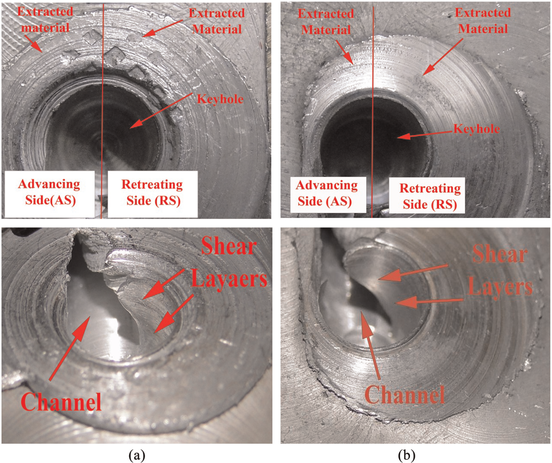
Keyhole created using stop-action technique for the fabricated channel in Figure 3: (a) SCP tool and (b) UCP tool.
In the keyholes in Figure 7, the layer of material (shear layers) exists around tool pin which pulls from the front to back of pin because of rotary direction of tool. According to Figure 7, the pulled material (shear layers) increases using the UCP tool. Therefore, the volume of material increases at the upper portion of AS (Step defect region). Therefore, the integration of channel roof is completed using UCP tool geometry and the Step defect disappears. This phenomenon is responsible to create regular shape of channel and decreases the channel perimeter value. Investigation of channel height in Figure 4 shows that the UCP tool increases the minimum channel height (32%) at the same process parameters. This phenomenon can be related to control the material and reduction in falling material into the channel cavity because of conical shape of tool pin.
It is shown in Figure 8 that the channel width remains approximately constant during channeling using MFSC process. Rashidi et al. 14 studied the material flow around the tool pin body using weakened broken tool pin technique. They demonstrated that the channel width forms because of the detachment of deposited shear layers of material from tool pin body behind the pin. Stability of channel width shows that during MFSC, the material flow behavior is regular and constant.
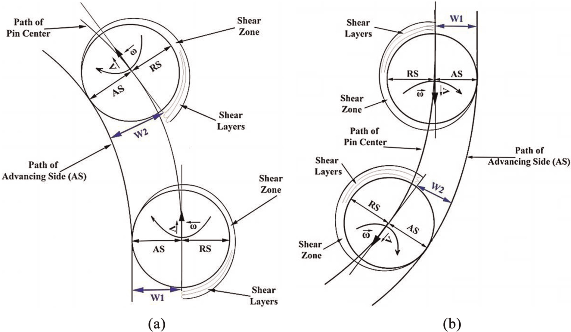
Channeling mechanism on curve directions when (a) AS along inner curve (D1) and (b) AS along the outer curve (D2).
Previous FSC work using threaded pin showed that all channels created shapes that are unstable in curve direction, and stability of channel is attributed to AS of tool. 3 Moreover, at some position along the curve, the channel is filled by material. This phenomenon is explained by downward force by shoulder which is increased with the material motion from the outer curve (AS) to the inner curve.
Figure 4 shows that the channels were stable along both curves, and Table 3 shows that the heights of channels also remained approximately constant along the curves. Therefore, in MFSC, the downward component of the force (forging action) by shoulder remains approximately constant. This result is in contrast to FSC. 3
According to Figure 5(a), the channel area is increased by moving toward location 4. On the other hand, according to Figure 4, it is evident that the channel width is responsible for the increase in channel area along the D1 curve. Rashidi et al. 14 studied the channel formation using SCP tool and reported that the distance between the shear layers detached from pin body in AS and RS behind the pin controls the value of channel width.
Figure 8(a) and (b) illustrates, respectively, the mechanism of increasing and decreasing channel width along the D1 and D2 curves. According to Rashidi et al., 6 who investigated the cross section of channel at different location on channeling line, the channel characteristics, including shape, area, and hydraulic diameter of channel, are approximately constant along channel. Besides, Figure 7 also shows that the channel width is constant along straight path. Accordingly, the shear layer motions are constant for each revolution of tool pin.
The channel formation mechanism along curve path can be explained using two theories. First, it is assumed that the volume of extracted material remains constant along both straight and curve paths. Second, it is assumed that the volume of extracted material changes with motion from the straight path to the curve path.
With respect to the first theory, the volume of extracted material remains constant; the material flow in process zone is constant. Consequently, the pulled material from front to back of pin is stable. This phenomenon occurs along the straight path and can be seen in Figure 8. According to Figure 8(a), when the tool pin moves from the straight path to curve path and AS is along the inner curve, the pulled material behind the pin tends to move far from pin center path. Thus, the channel width increases with moving on the first half of the curve direction. This growth of channel width is related to the length of curve path and increases continuously. Due to this phenomenon, the maximum width of channel occurs at the maximum point of curve (location 4). Decrease in channel width on the second half in the D1 curve also is due to access of shear layers to boundary between AS and RS. Figure 8(b) shows this mechanism when AS is along the outer curve. According to this figure, it is evident that channel width (W2) decreases with moving pin from the straight path to the D2 curve path. Due to this phenomenon, the minimum width of channel occurs at the minimum point of the D2 curve (location 4).
According to the first theory, the channel width variations should remain constant for both D1 and D2 curves. However, Table 3 shows that the variations of channel width along D2 is more less than D1. This phenomenon can be explained by the second theory.
Due to the second theory, the volume of extracted material changes, the volume of material is not constant in process zone and increases by moving from the straight path to the curve path. This phenomenon results in increasing the extracted material in front of tool and decreasing the extruded material from front to back of the pin. Increasing extracted material in curve paths causes strong variations of channel area along the D1. On the other hand, increasing extracted material in curve paths reduces the channel area variations along the D2.
On the other hand, Due to Figure 8, it is clear that the volume of extracted material increases with moving from AS to RS on the leading edge. It means that the extracted material in the RS is more larger than the AS. At front of pin body, Figure 8(a) shows that the location of pin center line is in AS when the AS is in the inner curve. Therefore, the path force increases in AS and the volume of extracted material increases in AS. Figure 8(b) also shows that the pin center path is located in RS when AS is in the outer curve. So, the path force increases in RS and the volume of extracted material increases in RS. Therefore, variations on location of the pin center path and asymmetric pattern of extracted material are responsible for increasing the volume of extracted material in the D2 path compared to the D1 path. Accordingly, the variations of channel area along curve paths can be described as follows: (a) continuous increase or decrease in the channel width due to D1 and D2 curves, respectively, (b) increase in extracted material when the path changes (straight path to curve path), and (c) asymmetric pattern of increasing extraction material due to change in path force location.
Indeed, when AS is along the inner curve, all three reasons lead to increase in the channel area. When AS is along the outer curve, the first reason leads to decrease in the channel area. However, the two other reasons lead to its increase. Therefore, the channel area experiences different values along curve paths.
Conclusion
In this study, the two different tool geometries are utilized to create channel. Decrease in Step defect, increase in height, and hydraulic diameter of channel are the advantages of UCP tool versus SCP tool. These advantages are attributed to improving the material flow on the channel roof. Material flow are studied using stop-action technique and demonstrated that the UCP tool is able to push more material to the upper portion of AS and improves the material flow on channel roof. Investigation of the channel created in curve directions showed that the UCP tool of MFSC can produce channel with high stable characteristics when the AS is along the outer curve. The shapes of channels at both curves are similar. Study on the mechanism of channel formation in curve direction shows that variations of channel properties are because of the displacement in the shear layers along curve and the increase in the volume of extracted material. Study on channel structure at vertical path shows that when AS is the inner route, the material is not able to fill the channel and the open passage is created by MFSC.
Footnotes
Declaration of conflicting interests
The author(s) declared no potential conflicts of interest with respect to the research, authorship, and/or publication of this article.
Funding
The author(s) received no financial support for the research, authorship, and/or publication of this article.