
Abstract
Cutting parameters and material properties have important effects on the quality of milled surface, which can be characterized by fractal dimension and surface roughness. The relationships between two surface parameters (surface roughness and fractal dimension) and material hardness, elongation, spindle speed and feed rate were investigated, respectively, in this study. Four carbon steels, that is, AISI 1020, Gr 50, 1045 and 1566, were milled with five spindle speeds and four feed rates on a computer numerical control machine. The surface topographies were measured with a three-dimensional profiler. The surface profiles were obtained by re-sampling the data points on the surface topography in the measurement direction. The surface roughness and fractal dimension were calculated from the two-dimensional profiles, where the fractal dimension was obtained by the root-mean-square method. The results showed that for specific spindle speed and feed rate, the roughness of the milled surface decreased with the workpiece hardness, whereas the elongation and fractal dimension increased with the hardness. Based on the material hardness and elongation, spindle speed and feed rate, empirical formulae were established to quantitatively estimate the surface roughness and fractal dimension. Moreover, the spindle speed and feed rate can be easily calculated from the empirical formulae to achieve a surface with the desired surface roughness and fractal dimension. The empirical formulae have been demonstrated with the experiments and were shown to be applicable in estimating the surface roughness and fractal dimension for all carbon steels in end milling. The results are instructive for the fractal dimension estimation of the machined surfaces of carbon steel, which has not been previously studied.
Introduction
The fractal dimension and surface roughness are the main parameters that characterize the quality of a machined surface. The former describes the self-similarity of the surface profile on different scales, which reflects the complexity and irregularity of the machined surface. The latter is defined as the arithmetic mean deviation of the profile height and indicates the variations in the peaks and valleys of a machined surface. Therefore, the fractal dimension and surface roughness are the two parameters that can be used to describe the surface profile from different perspectives, but one is not a substitute for the other. However, the surface roughness strongly depends on the resolution and the scan length of the roughness-measuring equipment. While the scale-independent fractal dimension can be used to characterize the rough surface at all length scales to overcome the disadvantages of surface roughness. Achieving a desired surface quality is of great importance in engineering. However, the surface finish is often affected by many factors, such as the machining parameters (i.e. spindle speed, feed rate and depth of cut), cutting tool properties (i.e. tool material and nose radius) and workpiece properties (i.e. workpiece hardness and elongation), and considerable research has been conducted on estimating the fractal dimension and surface roughness based on these factors.
The fractal structures are almost ubiquitous in the real world. It has the feature of self-similarity and self-affinity, with no characteristic scales, but contains the elements of all scales. These merits make fractal a useful tool to characterize the machined surface. In recent years, several researchers have investigated the use of fractals to describe machined surfaces.1,2 Yuan et al. 3 showed that a machined surface contains a large number of superimposed roughness patterns of various scales. These patterns indicated that engineering surfaces formed by turning, milling and grinding have a fractal structure, and the unique properties of a machined surface can be obtained by fractal analysis. The fractal dimension of a machined surface is closely related to the process used to create the surface, workpiece material, cutting conditions and cutter parameters. Based on fractal theory, Hasegawa et al. 4 obtained the fractal dimensions of various surfaces created by turning, electrical discharge machining and grinding and concluded that the fractal dimension of the surface depends on the processing method. Among these methods, the surface formed by electrical discharge machining has the largest fractal dimension, and the turning surface has the smallest. Grzesik and Brol 5 researched the turned surface of different workpiece materials. For the same cutting parameters, the authors found that the type of the material has a significant influence on the fractal dimension. For end milling operations, El-Sonbaty et al. 6 studied the relationship between the cutting conditions and fractal dimensions of the machined surfaces. The authors suggested that a smaller surface roughness and larger fractal dimension can be achieved with the appropriate selection of cutting parameters, namely, rotational speed, feed rate and vibration level. Sahoo et al. 7 investigated the effects of cutting parameters on the fractal dimension for three different materials. Their results showed that the spindle speed and cutting depth were the significant factors affecting the fractal dimension for mild steel. For brass, the significant factors were the spindle speed and feed rate, whereas the significant factor for aluminum was the cutting depth. Zhao et al. 8 studied the effects of grinding parameters on the fractal dimension in ultrasonic vibration grinding. The authors noted that the fractal dimension of a ground surface decreases with the feed rate, depth of cut and abrasive particle size.
Bhardwaj et al. 9 investigated the effects of the feed rate, spindle speed, depth of cut and nose radius on the surface roughness in the end milling of AISI 1019 steel. The experimental results demonstrated that the spindle speed, feed rate and nose radius had a significant effect on the surface roughness. Raju et al. 10 presented a surface roughness model for end milling that included the spindle speed, feed rate and depth of cut that were obtained using a genetic algorithm. The result revealed that the feed rate was the most significant parameter affecting the surface roughness (Ra), followed by spindle speed. The effect of the depth of cut was not regular. Zhang et al. 11 used the Taguchi method to determine the optimal cutting conditions for end milling. The experimental results indicated that the effects of the spindle speed and feed rate on the surface were greater than the effect of the depth of cut for milling. Wang and Chang 12 studied the effects of the spindle speed, feed rate and depth of cut on surface roughness for the aluminum alloy 2014-T6 in end milling using the response surface methodology. The study showed that the spindle speed and feed rate are the dominant factors determining the surface roughness. The workpiece hardness also has a significant influence on the surface roughness. Chinchanikar and Choudhury 13 and Aouici et al. 14 investigated the effects of the spindle speed, feed rate, workpiece hardness and depth of cut on the surface roughness. The results showed that the feed rate and workpiece hardness had statistically significant effect on the surface roughness Ra, which decreased with hardness.
There have been relatively few quantitative investigations of the effects of the material properties on the fractal dimension and roughness for a machined surface. For example, the hardness and elongation of the material may influence the fractal dimension for certain cutting parameters. Moreover, we are unaware of any studies on the variation law of the fractal dimension and surface roughness for the workpiece materials from the same category. We would like to know whether there are uniform formulae that can be used to estimate the roughness and fractal dimension for surfaces of carbon steels. To answer these questions, this study explores the relationship between material properties, cutting parameters and surface parameters (i.e. surface roughness and fractal dimension).
The article is organized as follows: in section “Experiments,” the experimental formulae are given. Four kinds of carbon steels which have different hardness and elongation are processed for various spindle speeds and feed rates on the computer numerical control (CNC) machine, and then, the surface topographies were measured with a three-dimensional (3D) profiler. In section “Roughness and fractal dimension of the milled surface,” the fractal dimensions of the milled surfaces are calculated by the root-mean-square (RMS) method. Based on the numerical results, relationships have been established from which both fractal dimension and surface roughness can be estimated by the material properties and cutting parameters. The confirmation tests and discussion are given in section “Confirmation experiments and discussion.” Finally, major conclusions of this study are drawn in the last section.
Experiments
Before calculation of the fractal dimension and surface roughness of the milled surface, some experiments were carried out in this section.
Material preparation
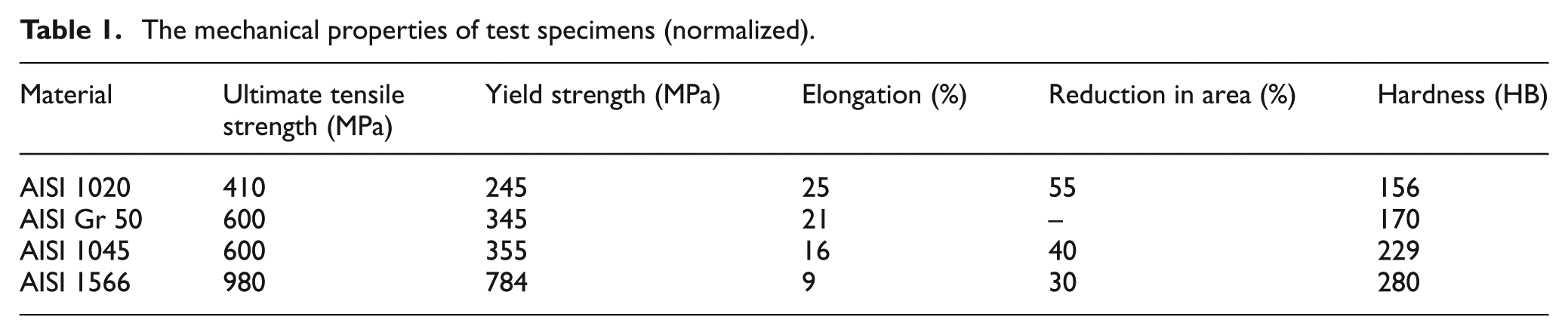
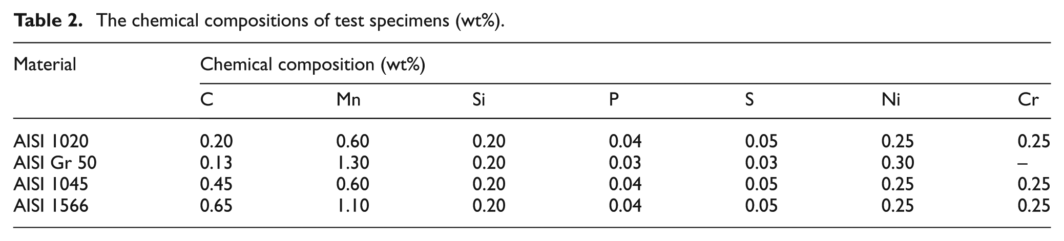
The mechanical properties of the materials from different categories, such as carbon steels, alloy steels and composites, differ greatly, and thus, the roughness and fractal dimension of a milled surface may behave differently for different kinds of the material. Therefore, we selected four materials, AISI 1020, Gr 50, 1045 and 1566, which are carbon steels. Their mechanical properties and chemical compositions are specified in Tables 1 and 2, respectively. Note that the hardness of the four materials in Table 1 is the raw hardness without any technological history. Prior to milling, the samples were machined to dimensions of 25 mm in diameter and 20 mm in height by turning.
The mechanical properties of test specimens (normalized).
The chemical compositions of test specimens (wt%).
Experimental conditions and methods
All specimens were milled using a Dema ML850A CNC machine with a FANUC 0i Mate-MD control system. The CNC machine was equipped with a 15-kW driver motor and had a maximum spindle speed of 8000 r/min. The cutters produced by WIDIA were square-ended end mills with four flutes and a diameter of 50 mm. The hardness, density and flexural strength for the AH 122 cutter were 91 HRA, 11.3 g/cm 3 and 1300 MPa, respectively. The positive angle of the cutter blade was 11°. For each specimen, a new, identical cutter was used to avoid the effects of tool wear on the surface finish. Figure 1(a) shows the milled surfaces of the four carbon steel specimens for various spindle speeds and a feed rate of 0.48 mm/rev. Figure 1(b) shows a typical surface prior to milling. An enlarged photograph of the AISI 1045 sample machined with a spindle speed of 0.48 mm/rev and a feed rate of 400 r/min is shown in Figure 1(c).
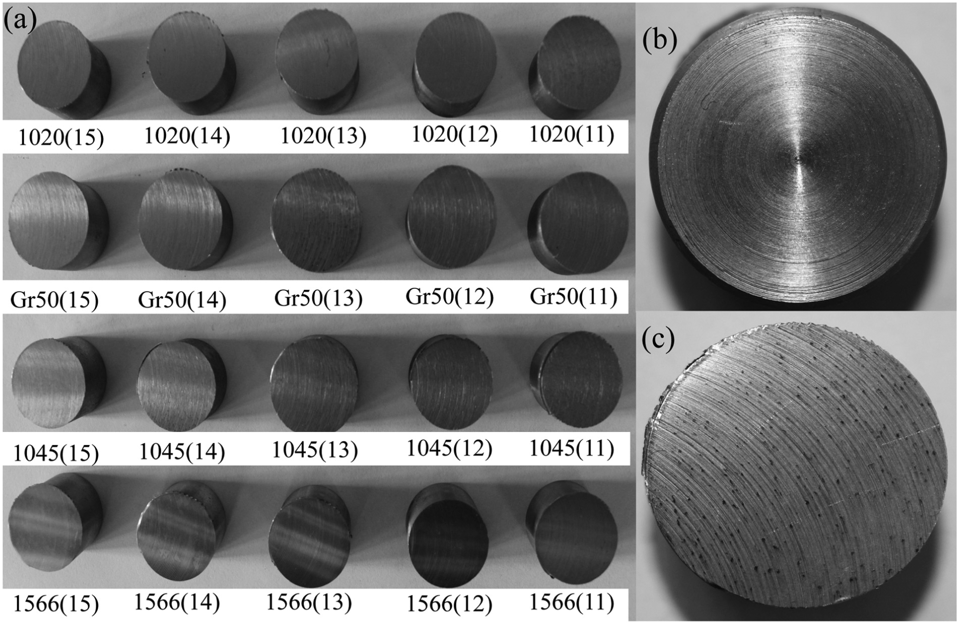
Photographs of the specimens. (a) The milled surfaces of the four carbon steel specimens for various spindle speeds and a feed rate of 0.48 mm/rev. The numbers 15, 14, 13, 12 and 11 in the figure represent the milling parameters. The first digit, “1,” represents a feed rate of 0.48 mm/rev, and the second digit, “5,”“4,”“3,”“2” or “1,” represents a spindle speed of 1200, 1000, 800, 600 or 400 r/min, respectively. (b) A typical surface prior to milling. (c) An enlarged photograph of the AISI 1045 specimen machined with the milling parameters f = 0.48 mm/rev and V = 400 r/min.
The feed rate and spindle speed have a greater effect on the surface roughness than the depth of cut,10,12 and the feed rate and cutting speed can be adjusted over a wider range than the depth of cut. Therefore, it is meaningful to study the effects of the feed rate and spindle speed on the surface roughness. For the reasons stated previously, we only studied the effects of the feed rate and spindle speed on the quality of the milled surface. The depth of cut was 0.5 mm in each case.
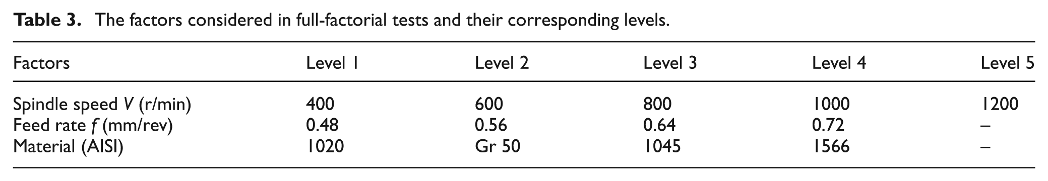
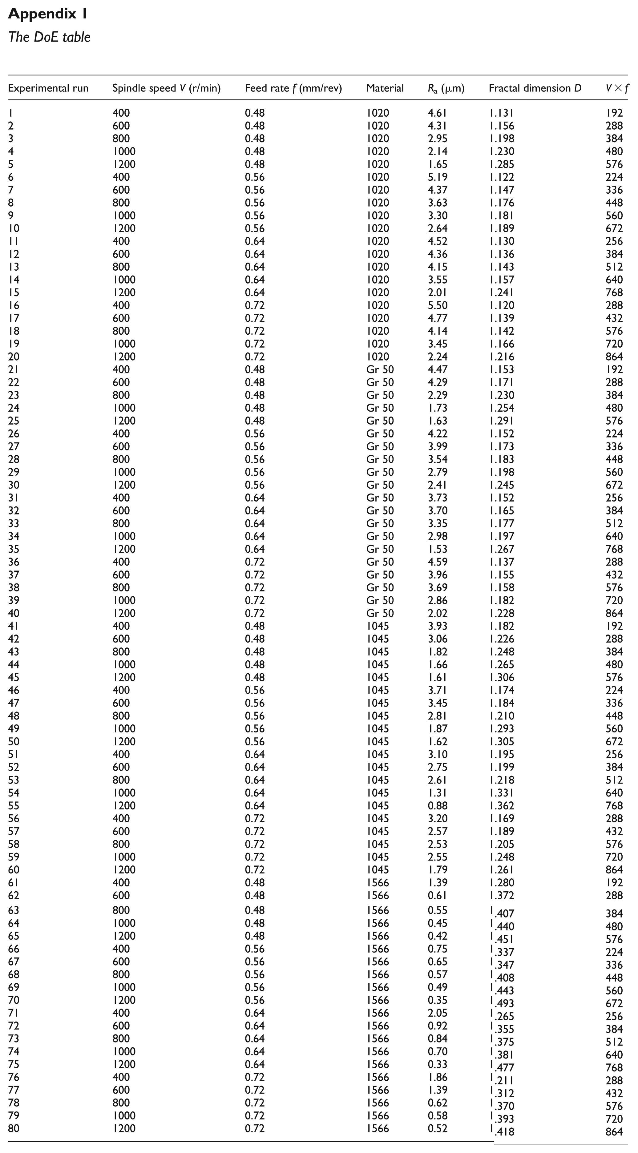
A parameter that represents the material properties can be defined by dividing the hardness by the elongation. Therefore, a three-factor, full-factorial design15,16 methodology was used to investigate the influences of the material hardness and elongation, spindle speed and feed rate on the fractal dimension and surface roughness of the finished surface. The advantages of a full-factorial analysis include the greater amount of information provided, more accurate experimental results and more reliable conclusions. For the four carbon steels, in order to ensure the quality of milled surface (Ra is less than 6.3 μm), the common feasible range for the spindle speed and feed rate was decided on the basis of machine capability, literature review and the manufacturer’s recommendation.17,18 The factors and their corresponding levels are shown in Table 3. The design of experiment (DoE) is detailed in Appendix 1. The total number of experiments was 4 × 5 × 4 = 80.
The factors considered in full-factorial tests and their corresponding levels.
Surface profile measurements
Prior to the measurement, the specimens were washed with acetone in an ultrasonic cleaner. The topographies of the milled surface were obtained with a KLA-Tencor MicroXAM2.5 × −50 × 3D surface profiler (Milpitas, CA, USA). The surface roughness and fractal dimension were directly calculated from the two-dimensional (2D) profile in this study. The steps for obtaining the 2D surface profiles were as follows:
Initial location: because the cutter was assumed to have a constant rotational speed and constant diameter, the initial measurement point could be chosen at any position on the milled surfaces.
Measurement direction: Figure 1(c) illustrates that the milled surface has a circular texture. Hence, the measurement direction should be perpendicular to the tangent direction of the surface texture.
Data acquisition: the 2D sectional profile was acquired by re-sampling the data points of the surface topography in the measurement direction. The sample length is 3.6 mm.
As an example, Figure 2(a) shows the surface topography of the AISI 1566 specimen machined with a spindle speed of 1000 r/min and a feed rate of 0.64 mm/rev. The size of the scanned area is 3.6 mm × 3.6 mm. The corresponding surface profile obtained from the surface topography is shown in Figure 2(b).
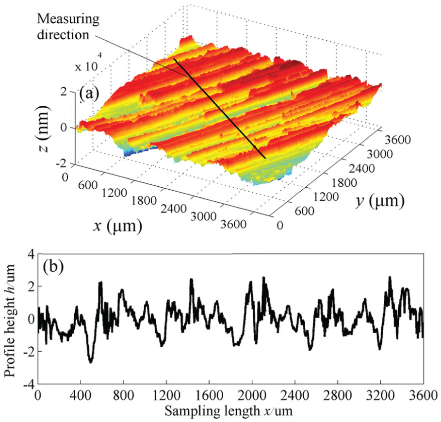
Surface topography and sectional profile of the AISI 1566 specimen machined with a spindle speed of 1000 r/min and a feed rate of 0.64 mm/rev: (a) the surface topography measured by the 3D surface profiler and (b) the sectional profile obtained from the surface topography in the measurement direction.
For each specimen, three surface profiles were obtained by repeating the aforementioned steps. The surface roughness was calculated based on the surface profile data. Thus, there were three values of surface roughness for each surface, and the means of the three values were used for the analysis. The calculated Ra of the surface profiles for various spindle speeds and the feed rates are presented in Appendix 1.
Roughness and fractal dimension of the milled surface
Method for calculating the fractal dimension
The fractal dimension describes the self-similarity of the measure for the surface profile on different scales. For different definitions of measure and scale, there are various calculation methods of the fractal dimension. Majumdar and colleagues19,20 proposed the power spectrum method to calculate the fractal dimension of steel surfaces, where frequencies were considered as scales and power spectra as measures. Wu 21 used the structure function method to calculate the fractal dimension of surface profile in which a series of increasing steps were defined as scales and the corresponding mean square values were regarded as measures. Furthermore, Zhu et al. 22 proposed the RMS method to calculate the fractal dimension of the machined surface. The results showed that the RMS method has good properties in the scale region. For this method, a series of increasing steps were thought as scales and RMS values for different steps were regarded as measures. Ji et al. 23 investigated the variation law of surface topography during running-in process and analyzed the surface profiles using the fractal dimension based on RMS method. They demonstrated the validity of RMS method for characterizing the machined surfaces. The following calculations are based on this method.
The profiles of a machined surface are known to exhibit the feature of geometric self-affinity. It can be characterized by the Weierstrass–Mandelbrot (W–M) fractal function, as demonstrated by Berry and Lewis, 24 which is given by
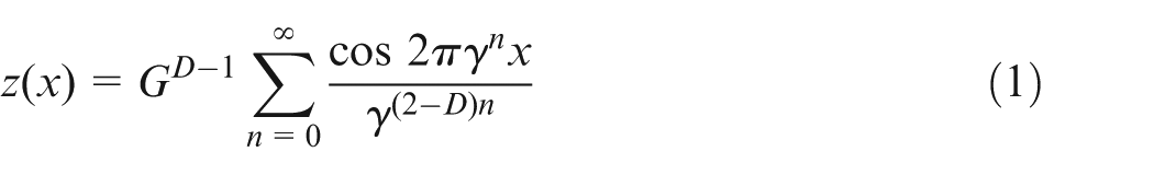
where z(x) is the profile height at the lateral distance x, D is the fractal dimension of the surface profile, G is a characteristic length scale, γ = 1.5 satisfies both phase randomization and high spectral density and the frequency modes γn correspond to the sampling length L as γn = 1/L. The power spectrum of the W–M function is
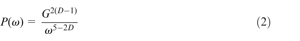
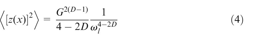
Hence, the mean square deviation of z(x) can be calculated by
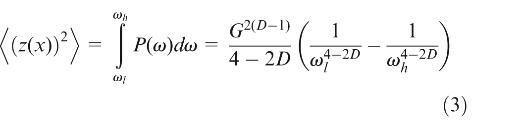
where ω is the frequency, <
Assuming
Then, the RMS measure σ(τ) follows a power law

where τ corresponds to ωl as ωl = π/τ, and C relating to the amplitude of all frequencies is the scale coefficient. The RMS measure σ(τ) versus the scale τ is a straight line on the log–log coordinates, that is

From equation (6), the fractal parameters D and C can be calculated from the slope and intercept of the log–log plot, respectively. In fact, the log–log plot is generally not an ideal straight line, and the fractal feature of a real surface only exists in a scale region. Therefore, the least squares method is introduced to operate the points in the scale region. The slope and intercept of the regression line are considered as the fractal dimension and scale coefficient individually.
To ensure the accuracy of the results, a common scale region that has better linearity must be selected before the calculation. Figure 3 displays the selection method of scale region for the condition of V = 600 r/min and f = 0.72 mm/rev. The double logarithmic graphs which are calculated based on the RMS method are given in the logσ(τ)–logτ plane. According to equation (5), the parameters D and C can be calculated by MATLAB programs. For each surface profile, three individual calculations are performed, and the mean values of the fractal dimension D are used for analysis. The calculated D of the surface profiles for various spindle speeds and feed rates are shown in Appendix 1.
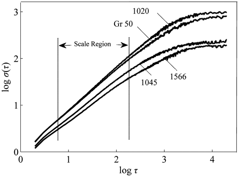
Selection of the scale region under the milling parameters of V = 600 r/min and f = 0.72 mm/rev.
Relationship between surface roughness, material properties and cutting parameters
In this subsection, the relationships between the roughness of the milled surface, workpiece hardness H, workpiece elongation δ, spindle speed V and feed rate f are discussed. The dependence of the surface roughness Ra on the material hardness H is clearly shown in Figure 4. Figure 4(a)–(d) illustrates that the surface roughness decreases with the material hardness regardless of the spindle speed. In other words, a smooth surface can be obtained more easily by milling for a harder material, which is consistent with those of previous studies.13,14 In addition to the material hardness, the surface roughness Ra also depends on the material elongation δ, as shown in Figure 5. The surface roughness increases with the material elongation. The interaction between the spindle speed and feed rate for the surface roughness is shown in Figure 6. The figure suggests that the surface roughness decreases with the spindle speed.
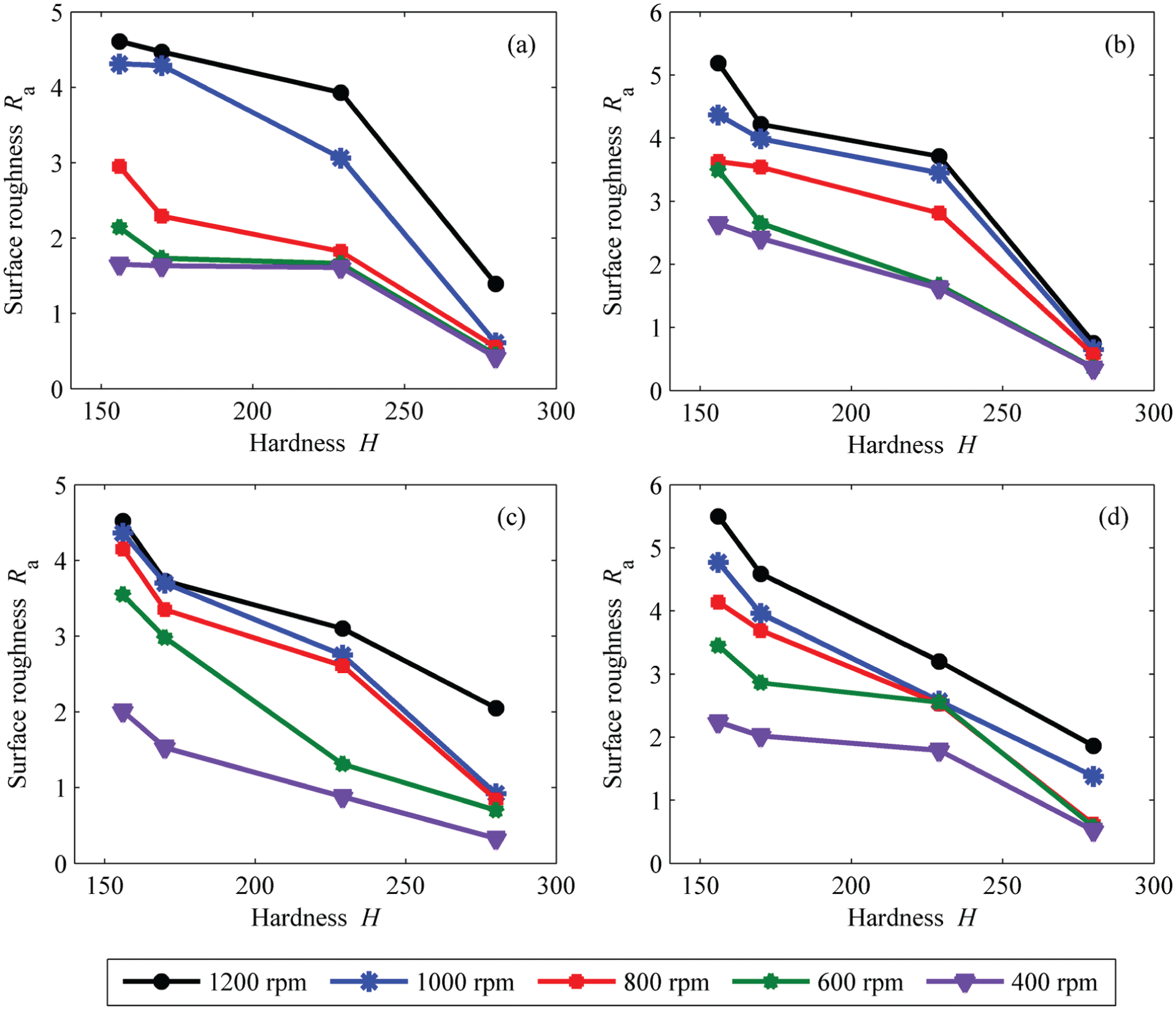
The surface roughness Ra versus the material hardness H for various feed rates and spindle speeds: (a) f = 0.48 mm/rev, (b) f = 0.56 mm/rev, (c) f = 0.64 mm/rev and (d) f = 0.72 mm/rev.
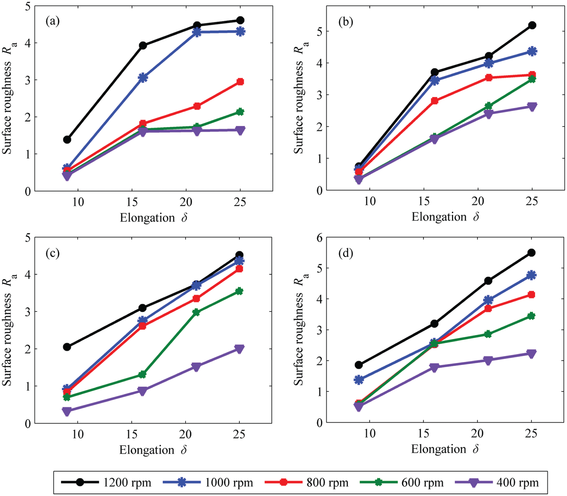
The surface roughness Ra versus the material elongation δ for various feed rates and spindle speeds: (a) f = 0.48 mm/rev, (b) f = 0.56 mm/rev, (c) f = 0.64 mm/rev and (d) f = 0.72 mm/rev.
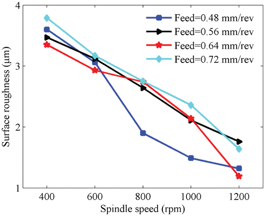
Surface roughness versus spindle speed for various feed rates.
The experimental results show that surface roughness Ra decreases with the material hardness H and increases with the material elongation δ. To further study the effects of the material properties on the surface roughness, we defined a new parameter, H/δ. The relationship between the surface roughness Ra and the parameter H/δ was investigated for various feed rates and spindle speeds. An empirical formula for the relationship is
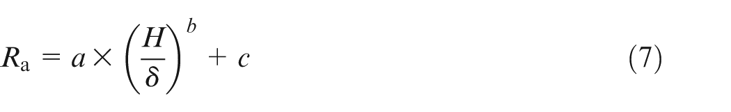
where a, b and c are the constants determined by the spindle speed and feed rate. The values of a, b and c for various cutting parameters were obtained based on the nonlinear least squares method.
Because of the limited space, Figure 7(a) shows the relationship between Ra and H/δ only for a spindle speed of 800 r/min, and Figure 7(b) shows the relationship between Ra and H/δ only for a feed rate of 0.56 mm/rev. The continuous curves shown in Figure 7 were obtained by fitting curves to the original data. The fitted curves illustrate that the surface roughness Ra decreases with the parameter H/δ, and the relationship is nonlinear. The values of a, b and c, which depend on the spindle speed and feed rate, are given in Table 4.
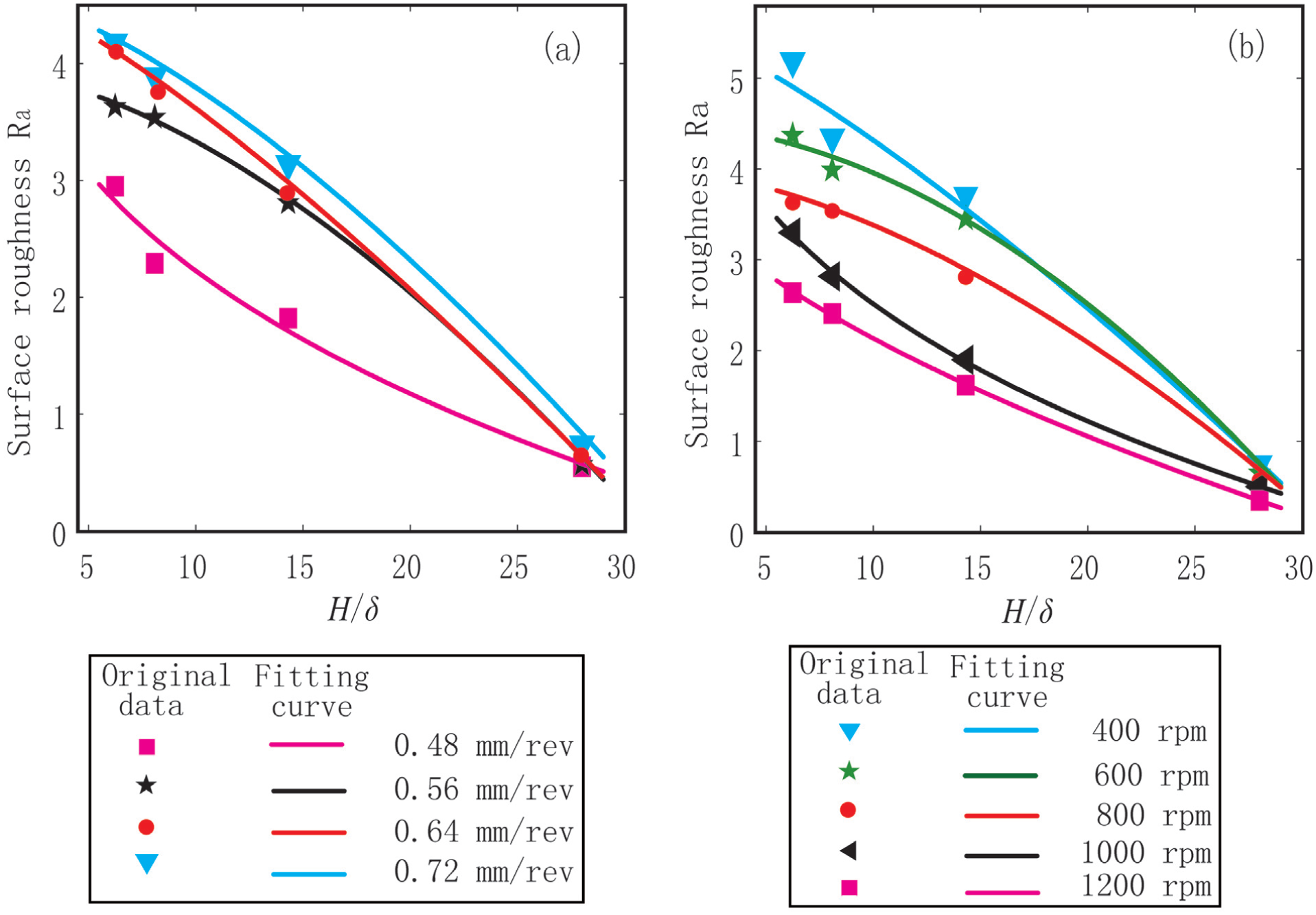
The relationship between the surface roughness Ra and the ratio of hardness to elongation H/δ for various milling parameters: (a) V = 800 r/min and (b) f = 0.56 mm/rev.
Values of parameters a, b and c in equation (7) for various cutting parameters.
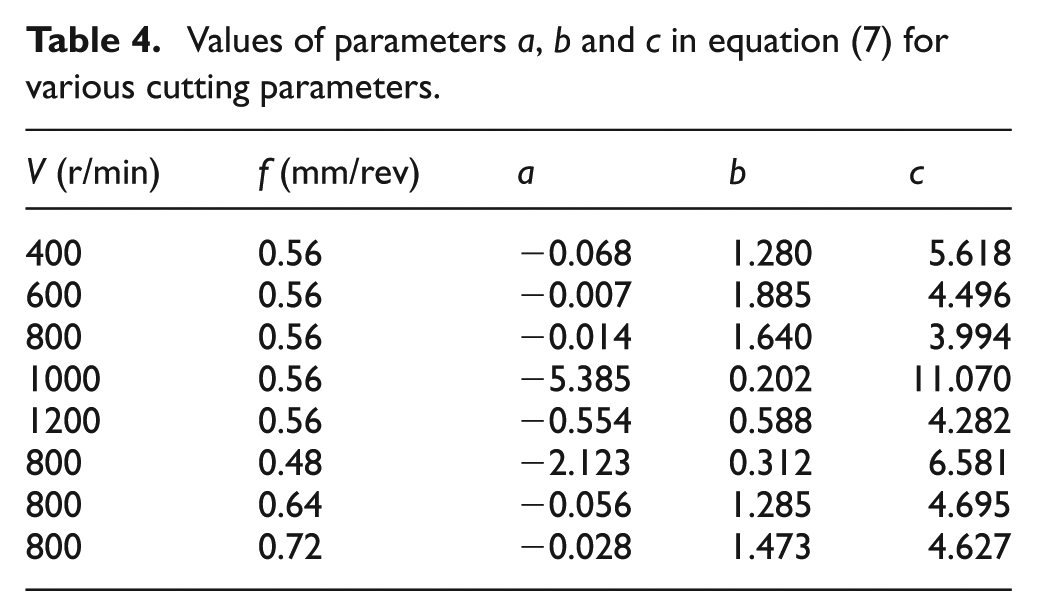
From Table 4 and equation (7), the surface roughness can be estimated for a specific workpiece material and a given set of cutting parameters. For example, the value of H/δ for AISI 1045 steel is 14.3, and the values of a, b and c are −0.014, 1.64 and 3.994, respectively, for a spindle speed of 800 r/min and a feed rate of 0.56 mm/rev. The estimated value of Ra obtained from equation (7) is 2.89 μm, whereas the experimentally determined value of Ra shown in Appendix 1 is 2.81 μm. The relative error between the experimental and estimated values of Ra is 2.84%, which demonstrates the accuracy of equation (7) and Table 4.
The spindle speed and feed rate can be easily obtained from the empirical formula to achieve a surface with the desired surface roughness rather than by trial-and-error or by referring to a manual. Furthermore, the empirical formula and the values of parameters a, b and c are suitable not only for the four carbon structural steels AISI 1020, Gr 50, 1045 and 1566 but for all carbon steels, which will be demonstrated in section “Confirmation experiments and discussion.” Therefore, for any carbon steels, the surface roughness can be estimated directly before end milling begins.
Relationship between fractal dimension, material properties and cutting parameters
For various spindle speeds and a constant feed rate, the relationship between the material hardness H and fractal dimension D is shown in Figure 8. The fractal dimension increases with the material hardness for any spindle speed, whereas the dimension decreases with the material elongation, as shown in Figure 9. Therefore, the fractal dimension D depends on the material hardness H and elongation δ for a given set of cutting parameters. The effects of the material properties on the surface roughness are the opposite of those on fractal dimension, which is consistent with the results of previous studies. Durst et al., 25 Issa et al. 26 and Zhang et al. 27 found that the fractal dimension D is strongly correlated with the conventional surface finish parameter Ra, that is, a smaller surface roughness leads to a higher fractal dimension.
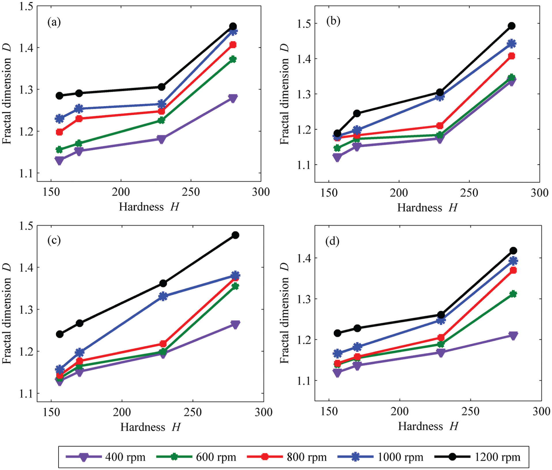
The surface fractal dimension D versus the material hardness H for various feed rates and spindle speeds: (a) f = 0.48 mm/rev, (b) f = 0.56 mm/rev, (c) f = 0.64 mm/rev and (d) f = 0.72 mm/rev.
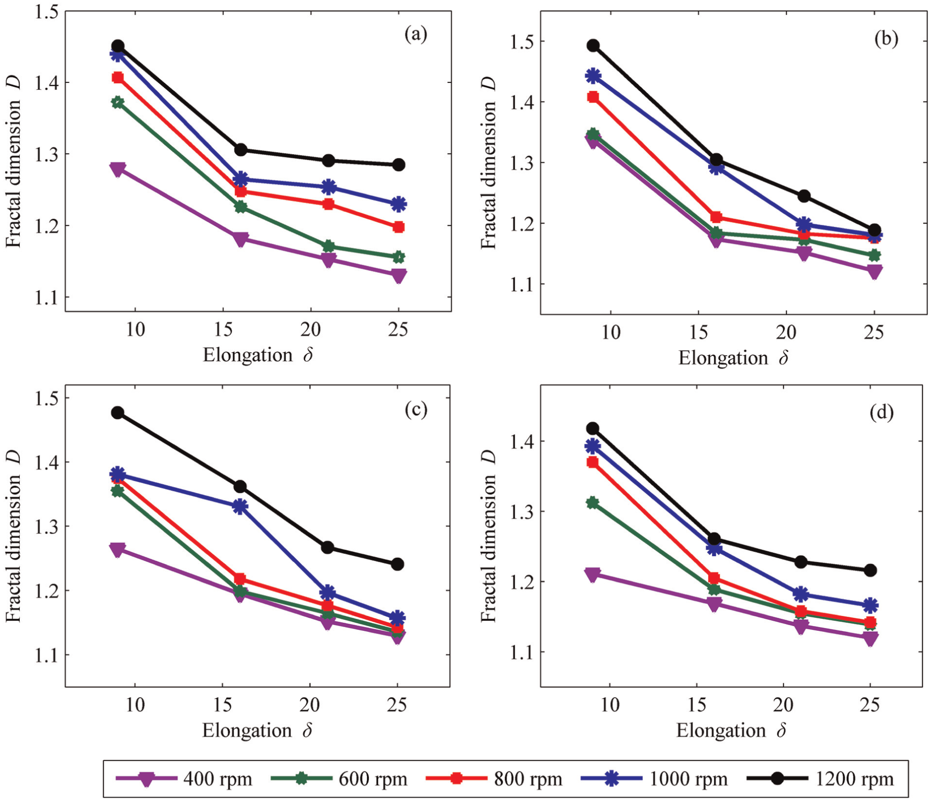
The surface fractal dimension D versus the material elongation δ for various feed rates and spindle speeds: (a) f = 0.48 mm/rev, (b) f = 0.56 mm/rev, (c) f = 0.64 mm/rev and (d) f = 0.72 mm/rev.
The effects of the spindle speed and feed rate on the fractal dimension were also studied, as shown in Figure 10. Figure 6 illustrates that the fractal dimension increases with the spindle speed, and a larger feed rate corresponds to a smaller value of the fractal dimension for the range of spindle feeds tested.
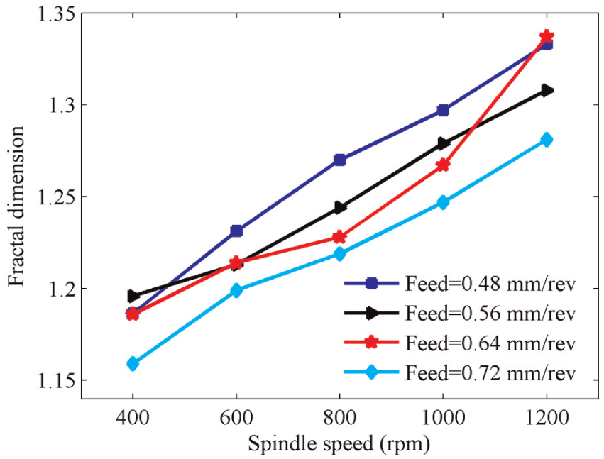
Fractal dimension versus spindle speed for various feed rates.
Similarly, the new parameter H/δ was also used to investigate the relationship between the fractal dimension D and the material properties. The relationship between the fractal dimension D and parameter H/δ was studied for various feed rates and spindle speeds. The empirical formula for the relationship is
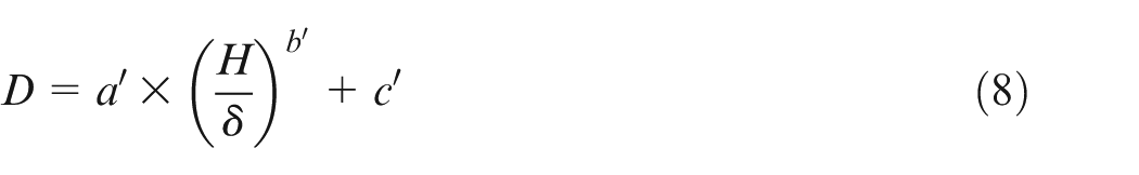
where a′, b′ and c′ depend on the cutting parameters V and f. The values of a′, b′ and c′ for various spindle speeds and feed rates were obtained using the nonlinear least squares method.
Because of the limited space, Figure 11(a) shows the relationships between D and H/δ only for a spindle speed of 800 r/min, and Figure 11(b) shows the relationships between D and H/δ only for a feed rate of 0.56 mm/rev. Curves were fitted to the data using the nonlinear least squares method, as shown in Figure 11, and the values of parameters a′, b′ and c′ for the cutting parameters in Figure 11 are given in Table 5. Equation (8) demonstrates that the fractal dimension of the milled surface can be estimated directly for given values of V and f.
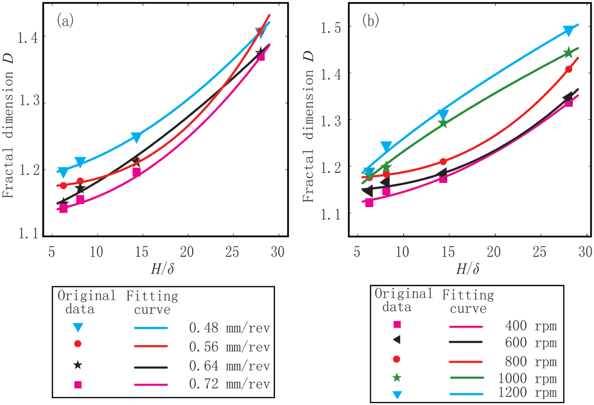
The relationship between the fractal dimension D and the ratio of hardness to elongation H/δ for various milling parameters: (a) V = 800 r/min and (b) f = 0.56 mm/rev.
Values of parameters a′, b′ and c′ in equation (7) for various cutting parameters.
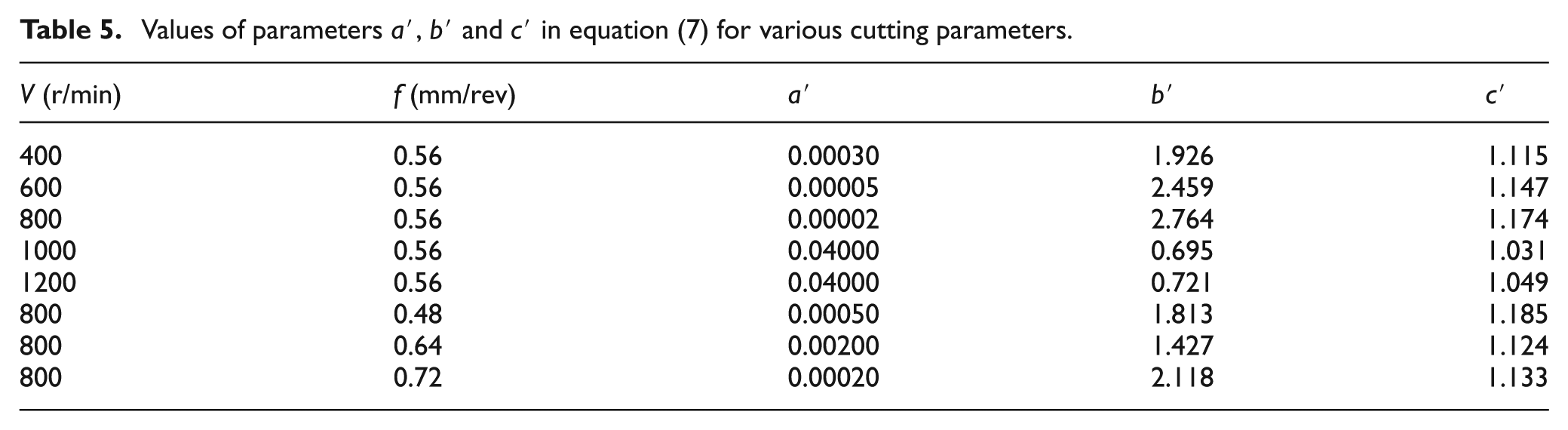
Moreover, for any carbon steel, the fractal dimension can be estimated using equation (8) and Table 5 if the workpiece material is known, which will be proved in section “Confirmation experiments and discussion.” Thus, the spindle speed and feed rate can be easily calculated from the empirical formula to achieve a surface with a high fractal dimension. The values of parameters a′, b′ and c′ in Table 5 are suitable only for milling.
Confirmation experiments and discussion
Confirmation experiments
In section “Roughness and fractal dimension of the milled surface,” the empirical formulae are established for estimating the surface roughness and fractal dimension under certain values of H/δ and cutting parameters. The formulae are obtained by calculating the four carbon steels AISI 1020, Gr 50, 1045 and 1566. As a matter of fact, it has widespread applicability to all carbon steels, which will be further supported through the confirmation experiments.
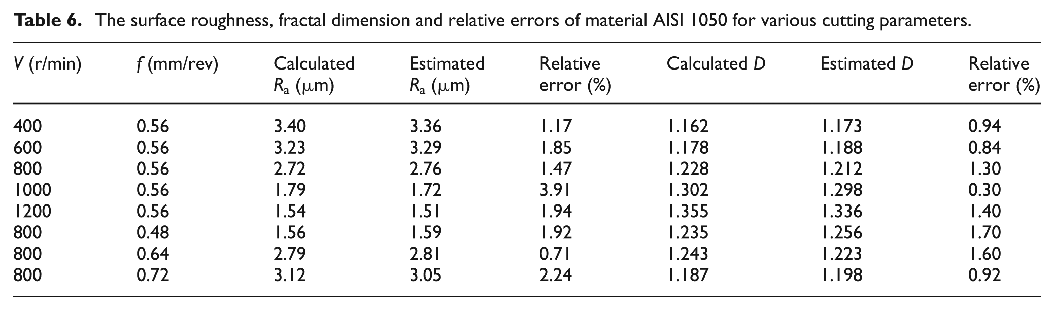
Eight specimens with carbon steel of AISI 1050 were milled with the cutting parameters shown in Tables 4 and 5. The elongation and hardness of AISI 1050 are 15% and 232 HB, respectively, thus the value of parameter H/δ is 15.4. The surface roughness and fractal dimension are calculated from the surface profiles, where the fractal dimension is obtained by the RMS method. The estimated Ra and D are obtained by substituting the parameter H/δ and the parameters shown in Tables 4 and 5 into equations (7) and (8), respectively. The relative errors between the calculated values from the experimental results and the estimated values from the empirical formulae are given in Table 6. For the surface roughness, the relative errors between calculated Ra and estimated Ra are less than 4%, while for the fractal dimension the relative errors between calculated D and estimated D are less than 2%, which indicates that the estimated Ra and D are very close to the calculated Ra and D. Therefore, the confirmation experiments demonstrate that the empirical formulae shown by equations (7) and (8) are suitable for other carbon steels.
The surface roughness, fractal dimension and relative errors of material AISI 1050 for various cutting parameters.
Discussion
The fractal dimension and surface roughness are the two parameters that can be used to describe the surface profile from different perspectives, but one is not a substitute for the other. For example, in case 41 (AISI 1045, V = 400 r/min, f = 0.48 mm/rev) in the DoE table, the surface roughness is 3.93 and the fractal dimension is 1.182. In case 39 (AISI Gr 50, V = 1000 r/min, f = 0.72 mm/rev), the surface roughness and fractal dimension are 2.86 and 1.182, respectively. The two surfaces have the same fractal dimension but different values of surface roughness. As another example, in case 61 (AISI 1566, V = 400 r/min, f = 0.48 mm/rev), the surface roughness is 1.39 and the fractal dimension is 1.28. In case 77 (AISI 1566, V = 600 r/min, f = 0.72 mm/rev), the surface roughness and the fractal dimension are 1.39 and 1.31, respectively. The two surfaces have the same surface roughness but different fractal dimensions. Thus, two surfaces cannot be well characterized or distinguished by only one of the two parameters. In this study, the milled surfaces were comprehensively characterized using the fractal dimension and surface roughness.
Previous studies in the literature mainly focused on the estimation of the fractal dimension of the machined surfaces for a certain material. For surfaces of other materials belonging to the same category, one has to conduct the experiments and calculate the fractal dimensions again, which is time consuming. In this study, we obtained general equations for the surfaces of all carbon steels rather than a certain material, and thus, the fractal dimension of a milled surface for a given set of cutting conditions can be estimated prior to the experiments. Carbon steel AISI 1050 was used as an example. The fractal dimensions of the milled surfaces were estimated from equations (7) and (8), as shown in Table 6. The results illustrate that the relative errors between the experimental values and estimated values are extremely small. Therefore, the empirical formulae, equations (7) and (8), are instructive for estimating the fractal dimension of a machined surface of carbon steel, a topic that has not been previously studied.
Conclusion
In this study, the relationships between the two surface parameters (surface roughness and fractal dimension) and material hardness and elongation, spindle speed and feed rate were studied. Specimens of four carbon steels, that is, AISI 1020, Gr 50, 1045 and 1566, were milled with five spindle speeds and four feed rates on a CNC machine. The surface topographies were measured with a 3D profiler. For each topography, three sectional profiles were obtained by re-sampling the data points in the measurement direction. The surface roughness and fractal dimension were calculated from the 2D profiles, where the fractal dimension was obtained by the RMS method. Several important and meaningful results were obtained in this study. For certain spindle speed and feed rate, the surface roughness decreased with the workpiece hardness, whereas the elongation and fractal dimension of the milled surface increased with the workpiece hardness. Based on the experimental data, empirical formulae were established, as shown in equations (7) and (8). These equations can be used to quantitatively estimate the surface roughness and fractal dimension as long as the material, spindle speed and feed rate are known. In addition, the spindle speed and feed rate can be easily calculated from the empirical formulae to achieve a surface with the desired surface roughness and fractal dimension. The empirical formulae, equations (7) and (8), were validated with the confirmation experiments. They were shown to be applicable in estimating the surface roughness and fractal dimension for all carbon steels, which has not been previously studied. So our results provide new insight.
Footnotes
Appendix
The DoE table
| Experimental run | Spindle speed V (r/min) | Feed rate f (mm/rev) | Material | Ra (μm) | Fractal dimension D | V × f |
|---|---|---|---|---|---|---|
| 1 | 400 | 0.48 | 1020 | 4.61 | 1.131 | 192 |
| 2 | 600 | 0.48 | 1020 | 4.31 | 1.156 | 288 |
| 3 | 800 | 0.48 | 1020 | 2.95 | 1.198 | 384 |
| 4 | 1000 | 0.48 | 1020 | 2.14 | 1.230 | 480 |
| 5 | 1200 | 0.48 | 1020 | 1.65 | 1.285 | 576 |
| 6 | 400 | 0.56 | 1020 | 5.19 | 1.122 | 224 |
| 7 | 600 | 0.56 | 1020 | 4.37 | 1.147 | 336 |
| 8 | 800 | 0.56 | 1020 | 3.63 | 1.176 | 448 |
| 9 | 1000 | 0.56 | 1020 | 3.30 | 1.181 | 560 |
| 10 | 1200 | 0.56 | 1020 | 2.64 | 1.189 | 672 |
| 11 | 400 | 0.64 | 1020 | 4.52 | 1.130 | 256 |
| 12 | 600 | 0.64 | 1020 | 4.36 | 1.136 | 384 |
| 13 | 800 | 0.64 | 1020 | 4.15 | 1.143 | 512 |
| 14 | 1000 | 0.64 | 1020 | 3.55 | 1.157 | 640 |
| 15 | 1200 | 0.64 | 1020 | 2.01 | 1.241 | 768 |
| 16 | 400 | 0.72 | 1020 | 5.50 | 1.120 | 288 |
| 17 | 600 | 0.72 | 1020 | 4.77 | 1.139 | 432 |
| 18 | 800 | 0.72 | 1020 | 4.14 | 1.142 | 576 |
| 19 | 1000 | 0.72 | 1020 | 3.45 | 1.166 | 720 |
| 20 | 1200 | 0.72 | 1020 | 2.24 | 1.216 | 864 |
| 21 | 400 | 0.48 | Gr 50 | 4.47 | 1.153 | 192 |
| 22 | 600 | 0.48 | Gr 50 | 4.29 | 1.171 | 288 |
| 23 | 800 | 0.48 | Gr 50 | 2.29 | 1.230 | 384 |
| 24 | 1000 | 0.48 | Gr 50 | 1.73 | 1.254 | 480 |
| 25 | 1200 | 0.48 | Gr 50 | 1.63 | 1.291 | 576 |
| 26 | 400 | 0.56 | Gr 50 | 4.22 | 1.152 | 224 |
| 27 | 600 | 0.56 | Gr 50 | 3.99 | 1.173 | 336 |
| 28 | 800 | 0.56 | Gr 50 | 3.54 | 1.183 | 448 |
| 29 | 1000 | 0.56 | Gr 50 | 2.79 | 1.198 | 560 |
| 30 | 1200 | 0.56 | Gr 50 | 2.41 | 1.245 | 672 |
| 31 | 400 | 0.64 | Gr 50 | 3.73 | 1.152 | 256 |
| 32 | 600 | 0.64 | Gr 50 | 3.70 | 1.165 | 384 |
| 33 | 800 | 0.64 | Gr 50 | 3.35 | 1.177 | 512 |
| 34 | 1000 | 0.64 | Gr 50 | 2.98 | 1.197 | 640 |
| 35 | 1200 | 0.64 | Gr 50 | 1.53 | 1.267 | 768 |
| 36 | 400 | 0.72 | Gr 50 | 4.59 | 1.137 | 288 |
| 37 | 600 | 0.72 | Gr 50 | 3.96 | 1.155 | 432 |
| 38 | 800 | 0.72 | Gr 50 | 3.69 | 1.158 | 576 |
| 39 | 1000 | 0.72 | Gr 50 | 2.86 | 1.182 | 720 |
| 40 | 1200 | 0.72 | Gr 50 | 2.02 | 1.228 | 864 |
| 41 | 400 | 0.48 | 1045 | 3.93 | 1.182 | 192 |
| 42 | 600 | 0.48 | 1045 | 3.06 | 1.226 | 288 |
| 43 | 800 | 0.48 | 1045 | 1.82 | 1.248 | 384 |
| 44 | 1000 | 0.48 | 1045 | 1.66 | 1.265 | 480 |
| 45 | 1200 | 0.48 | 1045 | 1.61 | 1.306 | 576 |
| 46 | 400 | 0.56 | 1045 | 3.71 | 1.174 | 224 |
| 47 | 600 | 0.56 | 1045 | 3.45 | 1.184 | 336 |
| 48 | 800 | 0.56 | 1045 | 2.81 | 1.210 | 448 |
| 49 | 1000 | 0.56 | 1045 | 1.87 | 1.293 | 560 |
| 50 | 1200 | 0.56 | 1045 | 1.62 | 1.305 | 672 |
| 51 | 400 | 0.64 | 1045 | 3.10 | 1.195 | 256 |
| 52 | 600 | 0.64 | 1045 | 2.75 | 1.199 | 384 |
| 53 | 800 | 0.64 | 1045 | 2.61 | 1.218 | 512 |
| 54 | 1000 | 0.64 | 1045 | 1.31 | 1.331 | 640 |
| 55 | 1200 | 0.64 | 1045 | 0.88 | 1.362 | 768 |
| 56 | 400 | 0.72 | 1045 | 3.20 | 1.169 | 288 |
| 57 | 600 | 0.72 | 1045 | 2.57 | 1.189 | 432 |
| 58 | 800 | 0.72 | 1045 | 2.53 | 1.205 | 576 |
| 59 | 1000 | 0.72 | 1045 | 2.55 | 1.248 | 720 |
| 60 | 1200 | 0.72 | 1045 | 1.79 | 1.261 | 864 |
| 61 | 400 | 0.48 | 1566 | 1.39 | 1.280 | 192 |
| 62 | 600 | 0.48 | 1566 | 0.61 | 1.372 | 288 |
| 63 | 800 | 0.48 | 1566 | 0.55 | 1.407 | 384 |
| 64 | 1000 | 0.48 | 1566 | 0.45 | 1.440 | 480 |
| 65 | 1200 | 0.48 | 1566 | 0.42 | 1.451 | 576 |
| 66 | 400 | 0.56 | 1566 | 0.75 | 1.337 | 224 |
| 67 | 600 | 0.56 | 1566 | 0.65 | 1.347 | 336 |
| 68 | 800 | 0.56 | 1566 | 0.57 | 1.408 | 448 |
| 69 | 1000 | 0.56 | 1566 | 0.49 | 1.443 | 560 |
| 70 | 1200 | 0.56 | 1566 | 0.35 | 1.493 | 672 |
| 71 | 400 | 0.64 | 1566 | 2.05 | 1.265 | 256 |
| 72 | 600 | 0.64 | 1566 | 0.92 | 1.355 | 384 |
| 73 | 800 | 0.64 | 1566 | 0.84 | 1.375 | 512 |
| 74 | 1000 | 0.64 | 1566 | 0.70 | 1.381 | 640 |
| 75 | 1200 | 0.64 | 1566 | 0.33 | 1.477 | 768 |
| 76 | 400 | 0.72 | 1566 | 1.86 | 1.211 | 288 |
| 77 | 600 | 0.72 | 1566 | 1.39 | 1.312 | 432 |
| 78 | 800 | 0.72 | 1566 | 0.62 | 1.370 | 576 |
| 79 | 1000 | 0.72 | 1566 | 0.58 | 1.393 | 720 |
| 80 | 1200 | 0.72 | 1566 | 0.52 | 1.418 | 864 |
Declaration of conflicting interests
The author(s) declared no potential conflicts of interest with respect to the research, authorship, and/or publication of this article.
Funding
The author(s) disclosed receipt of the following financial support for the research, authorship, and/or publication of this article: This project was supported by the National Natural Science Foundation of China (Grant Nos 51375480 and 51305441) and the Priority Academic Program Development of Jiangsu Higher Education Institutions.